Article

Methodology of Excavator System Energy Flow-Down

Department of Mechanical Engineering, Ajou University, Suwon 16499, Gyeonggi, Korea
*
Author to whom correspondence should be addressed.
Energies 2020, 13(4), 951; https://doi.org/10.3390/en13040951
Submission received: 22 January 2020 / Revised: 12 February 2020 / Accepted: 19 February 2020 / Published: 20 February 2020
(This article belongs to the Section C: Energy Economics and Policy)

Abstract

:
Due to the strengthening of air-quality regulations, researchers have been investigating methods to improve excavator energy efficiency. Many researchers primarily conducted simulation studies employing mathematical models to analyze the energy consumption of excavator systems, which is necessary to examine the fuel efficiency improvement margin and the improvement effect. However, to effectively study the improvement of excavator efficiency, the real-time energy consumption characteristics must be examined through simulations and analyses of actual equipment-based energy consumption. Accordingly, this study establishes an energy flow-down model for the entire excavator system based on actual equipment tests. A measurement system is built to measure the required data, thereby establishing an experimental methodology for modeling each component. This paper presents an excavator system energy flow-down methodology that integrates the energy flow-down model, measurement system, and experimental methodology. This methodology was applied to dig and dump operations, and the energy consumption characteristics were analyzed. An analysis of the operating modes indicates that 59.8% of the total fuel energy was consumed in the engine system, 17% in the hydraulic system, and 23.2% in the hydraulic actuation systems. The methodology can be used to help analysis of the fuel efficiency improvement margin under various conditions.

1. Introduction

Excavators are multi-linked construction machinery consisting of a boom, an arm, and a bucket. As their multi-linked structure enables various movements and high usability, they are being extensively utilized. However, excavators consume more fuel per unit area than other construction machinery [1]. As a result, greenhouse gases emitted by hydraulic excavators make up a large proportion of the greenhouse gas (CO2) emitted by construction machinery [2,3].
In the case of bulldozers and dump trucks, which are the most commonly used construction machinery, the work produced by the engine is transferred to the wheels of the equipment through the drive system; for dump trucks in particular, more than 30% of the consumed fuel is used for the actual work performed by the equipment [4]. In the case of loaders, the engine work is directly transferred to the wheels simultaneously with the operation of the hydraulic system [5,6]. Conversely, excavators convert the engine work into hydraulic energy, as various operations, including traveling, digging, dumping, and grinding, are performed according to the user’s requests. Consequently, excavators have a low energy efficiency compared to the actual workload. For this reason, as the issue of air quality intensifies, it is becoming more important to improve the energy efficiency of excavators.
The excavator operating systems can be classified into the engine system, hydraulic system, and hydraulic actuation system. The energy efficiency of the excavator also varies with each system, and numerous studies considering this are in progress.
In the engine field, with tightening regulations on air quality, researchers have performed studies to meet engine efficiency and performance requirements within emission regulations that satisfy EPA Tier 4. Studies are also being conducted on applying engine cylinder deactivation technology, which is commercially available in automobiles, to improve efficiency deterioration caused by the frequent load fluctuations of excavator engines [7].
In the hydraulic system field, various control methods such as the positive control system, load sensing system [8], virtual bleed-off (VBO) system [9], and independent metering valve (IMV) [10], displacement controlled hydraulic system (DC) [11] have been used or proposed to not only improve the efficiency of the hydraulic pump, but also enhance the efficiency of the system through hydraulic system control.
Increasing energy efficiency in the hydraulic actuation system is being investigated in terms of recovering potential energy and inertia generated during excavator operation. Methods for recovering boom energy by adding a cylinder and accumulator to the existing boom hydraulic circuit [12], the hydraulic motor connected to the engine shaft [13], and accumulators and hydraulic motors (added to the hydraulic circuit) [9,14] have been studied. In addition, recovery methods through electrical systems and storage devices have been studied [15].
In addition to the aforementioned studies on efficiency improvement, researchers have been actively investigating hybridization schemes (to improve the efficiency of the entire excavator system), hybrid systems based on an electrical system [16,17,18,19] used in automobiles, and hydraulic hybrid excavators (HHEC) based on common pressure rail [20]. Additionally, macro excavator hybrid studies using the above-mentioned DC system [21,22,23,24] and hybridization through direct driven hydraulic drive (DDH) have been studied [25,26,27,28].
As such, studies for improving the efficiency of excavators are underway in various fields; to examine the effectiveness of these methods during applications, it is necessary to analyze the energy consumption characteristics of the excavator. For this purpose, researchers have created energy consumption models [29] through mathematical models and analysis of excavator systems, and applied them to simulation tools (MATLAB Simulink, AMESim®) [30,31]. By expanding this, simulation studies on the energy efficiency of hybrid excavators [32], as well as research on efficiency improvement concepts through simulations are in progress [33]. In addition to energy consumption analysis through simulation, researchers have proposed energy consumption analysis methodologies through system efficiency as well as fixed and variable energy consumption concepts [34].
Many researchers primarily conducted simulation studies employing mathematical models to analyze the energy consumption of excavator systems, which is necessary to examine the fuel efficiency improvement margin and the improvement effect. However, this study proposes a methodology for analyzing the real-time energy consumption characteristics of excavators based on data measured in real time, with a focus on the measurement and analysis of actual equipment tests. This study also distinguishes the components that consume energy generated from fuel for the entire excavator system and proposes a measurement system that can measure the energy consumption of each component. The actual energy consumption of the components during operation is analyzed using the real-time data measured by the measurement system and the energy consumption component model.

2. Excavator System Energy Flow

As shown in Figure 1, the excavator system consists of an engine system, a hydraulic system, and hydraulic actuation systems. The engine converts the injected fuel energy into mechanical energy and delivers it to each accessory and the hydraulic system. The delivered mechanical energy is subsequently converted into hydraulic energy through a hydraulic pump, transferred to hydraulic cylinders and hydraulic motors, and converted to mechanical energy for performing necessary operations.
In this process, losses occur due to various factors in each part; by identifying these factors in each component and analyzing them, the energy consumption characteristics during equipment operation can be examined.
For this purpose, the energy consumption components in each system must first be identified. We classified the engine system, hydraulic system, and hydraulic actuation systems into detailed energy consumption components, formulated equations, and used these equations to analyze the energy flow of the entire excavator. The nomenclature of the variables used in the equations is shown in Table 1.

2.1. Energy Flow Model in the Engine System

The engine converts fuel energy into heat energy through the combustion process, from which energy is transferred to the piston, excluding heat loss due to high-temperature exhaust gases and heat transfer to the engine block and coolant; this is subsequently converted into mechanical energy. The converted mechanical energy is used by various energy consumption components to drive the engine, and the energy is transferred to the hydraulic system. As such, a schematic of the energy flow in the engine system is shown in Figure 2.
Figure 2 can be defined in equations as follows.
W b r a k e = m f Q L H V W t h e r m o d y n a m i c   l o s s W i n d . g r o s s W e n g i n e   t o t a l   f r i c t i o n
W i n d . g r o s s = B D C , c o m p r e s s i o n B D C , e x p a n s i o n P c y l   d V c y l
W t h e r m o d y n a m i c   l o s s = m f Q L H V W i n d . g r o s s
W e n g i n e   t o t a l   f r i c t i o n = W e g f + W p u m p i n g + W a l t + W c o o l i n g   f a n
The energy that the engine finally transfers to the hydraulic system is indicated by engine brake work, as shown in Equation (1). The engine brake work is the energy remaining after the various consumption components have consumed energy for operating the engine; to determine this value, the injected fuel energy and energy consumption of each component when the engine is operated must be known.
The fuel energy consumed during equipment operation is expressed by the mass of fuel consumed and the lower heating value. A volumetric fuel flowmeter was installed in the equipment to measure the cumulative fuel quantity during operation. However, the aforementioned method cannot measure the fuel level in real time due to the characteristics of the fuel flowmeter; thus, for real-time fuel energy analysis, the electronic control unit (ECU) fuel quantity was measured through the controller area network (CAN) communication of the equipment and compared with the fuel flowmeter to investigate the reliability of the ECU’s fuel quantity [35].
As a result, the difference in the total fuel quantity was accurate to within 1.5% at the start and end of equipment operation, and the fuel energy was derived using the aforementioned fuel quantity measurement techniques.
The engine converts fuel energy into heat energy through combustion, from which energy is transferred to the piston, excluding heat loss due to high-temperature exhaust gases, heat transfer to the engine block and coolant; this is subsequently converted into mechanical energy. To determine the energy lost in this process, it can be directly predicted through detailed engine combustion models or indirectly calculated by measuring the exhaust gas composition, exhaust temperature, coolant flow rate, and temperature. In this study, however, without separating the aforementioned components in detail, the variety of heat loss is indirectly defined as thermodynamic loss by measuring the mechanical energy converted through actual piston movement.
To define the thermodynamic loss, the converted mechanical energy must first be known. This is represented by gross indicated work and expressed by Equation (2). Through this, the thermodynamic loss is expressed by Equation (3) [36].
The converted mechanical energy (excluding the aforementioned loss) is used by several components required to drive the engine (until it is transferred to the hydraulic system) and subsequently converted into hydraulic energy. This is defined as the engine total friction work and classified into pumping loss, alternator work, cooling fan work, and engine mechanical friction work, as shown in Figure 2 and Equation (4). Among these, engine mechanical friction work was defined by integrating the loss of components of excluding the aforementioned devices and the engine friction [37]. The aforementioned engine total friction work requires modeling for each component and is described in Section 3.

2.2. Energy Flow Model in the Hydraulic System

The engine brake work transferred from the engine is supplied to the main pump and converted into hydraulic energy, which is supplied to the main control valve (MCV) and subsequently delivered to the hydraulic actuation system. Loss occurs in each part of this process; the resulting energy flow is shown in Figure 3.
The energy flow model of Figure 3 can be expressed by Equation (5), in which the MCV output energy is the energy supplied to the hydraulic actuation system.
W M C V , o u t = W b r a k e W p u m p   l o s s W M C V   l o s s W w o r k i n g   f l u i d   f a n
W M C V , o u t = W h y d r a u l i c   a c t u a t o r
In the process wherein mechanical energy transferred to the main pump is converted into hydraulic energy and transferred to the main control valve (MCV), mechanical friction, pressure, and flow losses occur in the pump. This loss varies with the pump operating conditions and can be obtained through component tests or simulation modeling. In this study, however, for real-time analysis through measurement, the main pump input work, which can be determined from Equation (7), and the pump pressure and flow rate measured, as shown in Equation (8), were used to calculate the main pump output hydraulic energy. The difference between the two components was defined as the main pump loss, as shown in Equation (9).
The energy consumption model of the working fluid fan system, an energy consumption component required to determine the main pump input energy, is described in Section 3
W p u m p , i n = W b r a k e W w o r k i n g   f l u i d   f a n
W p u m p ,   o u t = P p u m p ,   o u t × Q ˙ p u m p ,   o u t d t
W p u m p   l o s s = W p u m p ,   i n W p u m p ,   o u t
In the process of transferring the hydraulic energy generated from the main pump to the hydraulic actuation systems, the MCV controls the flow path of the hydraulic energy. In the MCV, pressure loss due to the pipelines and valves, as well as flow loss due to main pump control occur.
This study defined the difference between the pump output energy transferred to the MCV and the energy transferred to the hydraulic actuation systems as MCV loss, as shown in Equation (10).
W M C V   l o s s = W p u m p ,   o u t W M C V ,   o u t

2.3. Energy Flow Model in the Hydraulic Actuation System

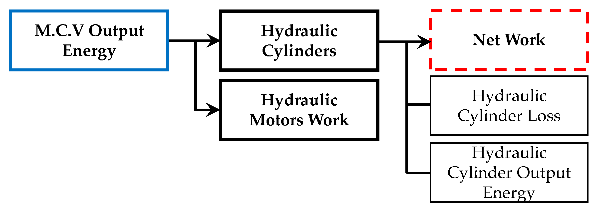
The hydraulic energy transferred to the MCV is transferred to each hydraulic actuation system; the actuators can be classified into the hydraulic cylinder and hydraulic motor, according to the driving method. Figure 4 shows a schematic of the energy flow.
The hydraulic energy transferred to the hydraulic motor is used to move the excavator and turn the turret.
The hydraulic energy transferred to the hydraulic cylinders is used to drive the boom, arm, and bucket. This is expressed in Equation (11). The energy transferred to each actuator is shown in Equations (12) and (13), respectively.
W M C V ,   o u t = W h y d r a u l i c   c y l i n d e r + W h y d r a u l i c   m o t o r
W h y d r a u l i c   c y l i n d e r = P c y l i n d e r ,   i n × Q ˙ c y l i n d e r   c y l . d t
W h y d r a u l i c   m o t o r = P m o t o r ,   i n × Q ˙ m o t o r ,   i n d t
By examining the hydraulic cylinders in detail, it can be observed that the transferred hydraulic energy (of the hydraulic cylinders) moves the piston, thus converting the hydraulic energy into mechanical energy. In this process, pressure and flow loss occur from the hydraulic energy transfer and output hydraulic energy (according to double-cylinder operation). Furthermore, mechanical friction loss occurs due to the operation of hydraulic actuation system. This study defined hydraulic cylinder loss by integrating the hydraulic energy loss generated during the hydraulic energy transfer and the mechanical frictional loss generated during hydraulic actuation system operation. This is expressed in Equation (14).
W w o r k , n e t = W c y l i n d e r , i n W c y l i d e r , o u t W c y l i d e r   l o s s
The net work refers to the pure work performed through the cylinder, which is the sum of positive work and negative work determined by the cylinder’s direction of motion and transfer of force. The output hydraulic energy is given by Equation (15), and the cylinder loss is described in Section 3.
W c y l i n d e r , o u t = P c y l i n d e r , o u t × Q ˙ c y l i n d e r , o u t d t

3. Modeling of Energy Consumption Component

3.1. Modeling of Engine Total Friction

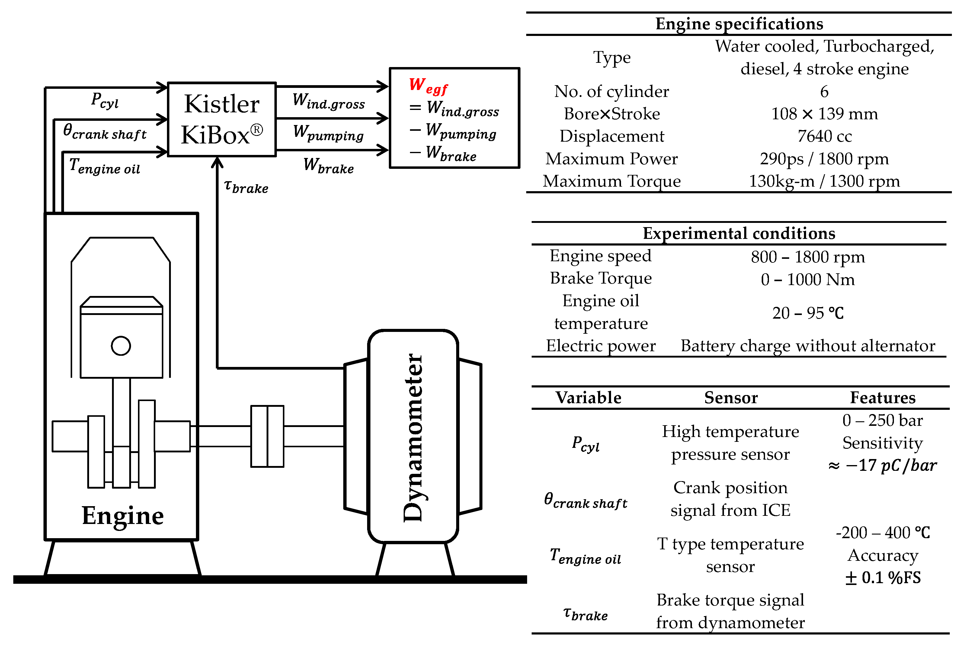
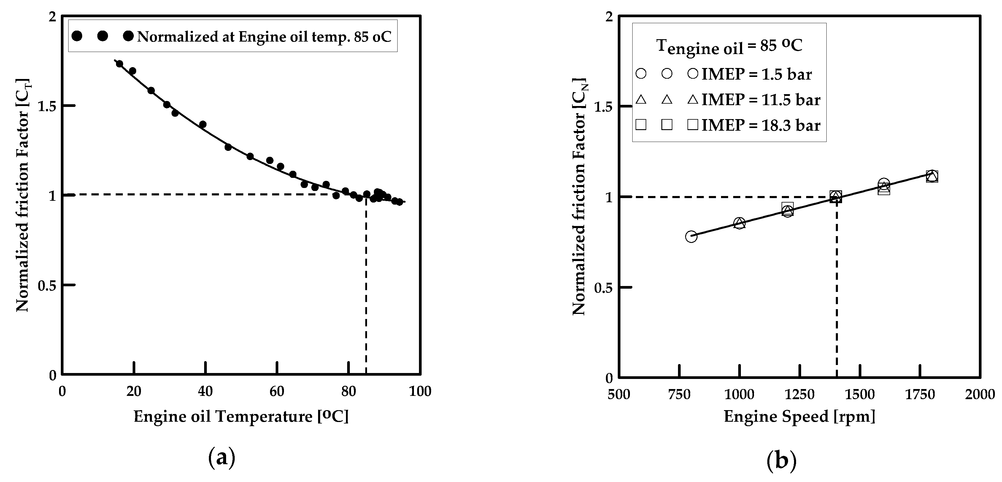
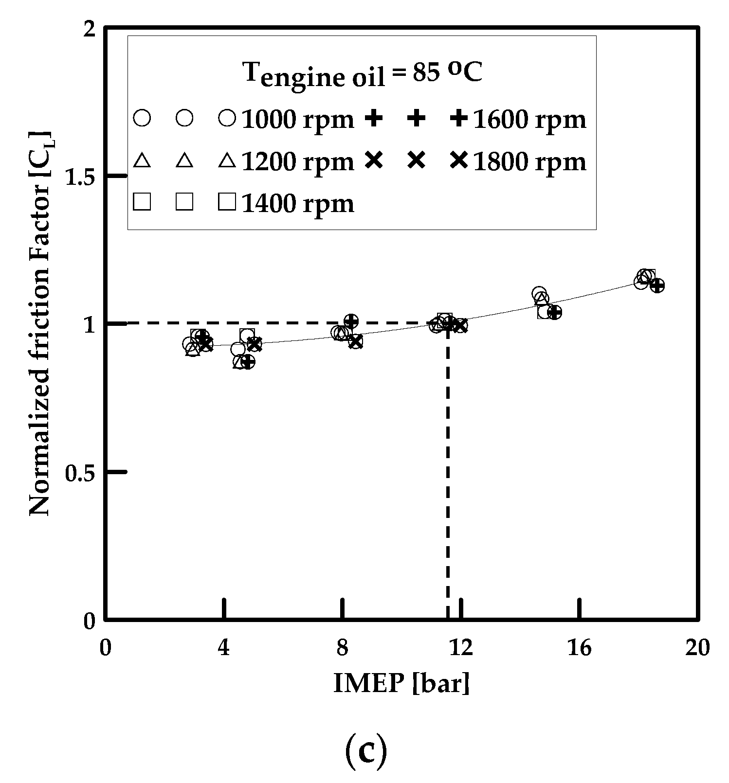
The engine total friction work defined in Section 2.1 is given in Equation (4). The engine mechanical friction work refers to the engine basic friction and accessory drive work (not defined above). This item is essential for driving the engine; in this study, the engine bench test was conducted to perform a real-time analysis within the measurable factors. The engine bench test set up, test conditions, and sensor specifications are shown in Figure 5. The factors affecting the engine mechanical friction are engine speed, engine load, and engine oil temperature. Each was varied to perform the component test, and models were built based on the results. Based on the engine mechanical friction in the main operating area, the normalized friction factor was defined, as shown in Equation (16).
W e g f = C T C N C L W e g f , base where { C T = friction   torque   at   T / friction   torque   at   T = 85   ° C C N = friction   torque   at   N / friction   torque   at   N = 1400   rpm C L = friction   torque   at   IMEP / friction   torque   at   IMEP = 11.5   bar
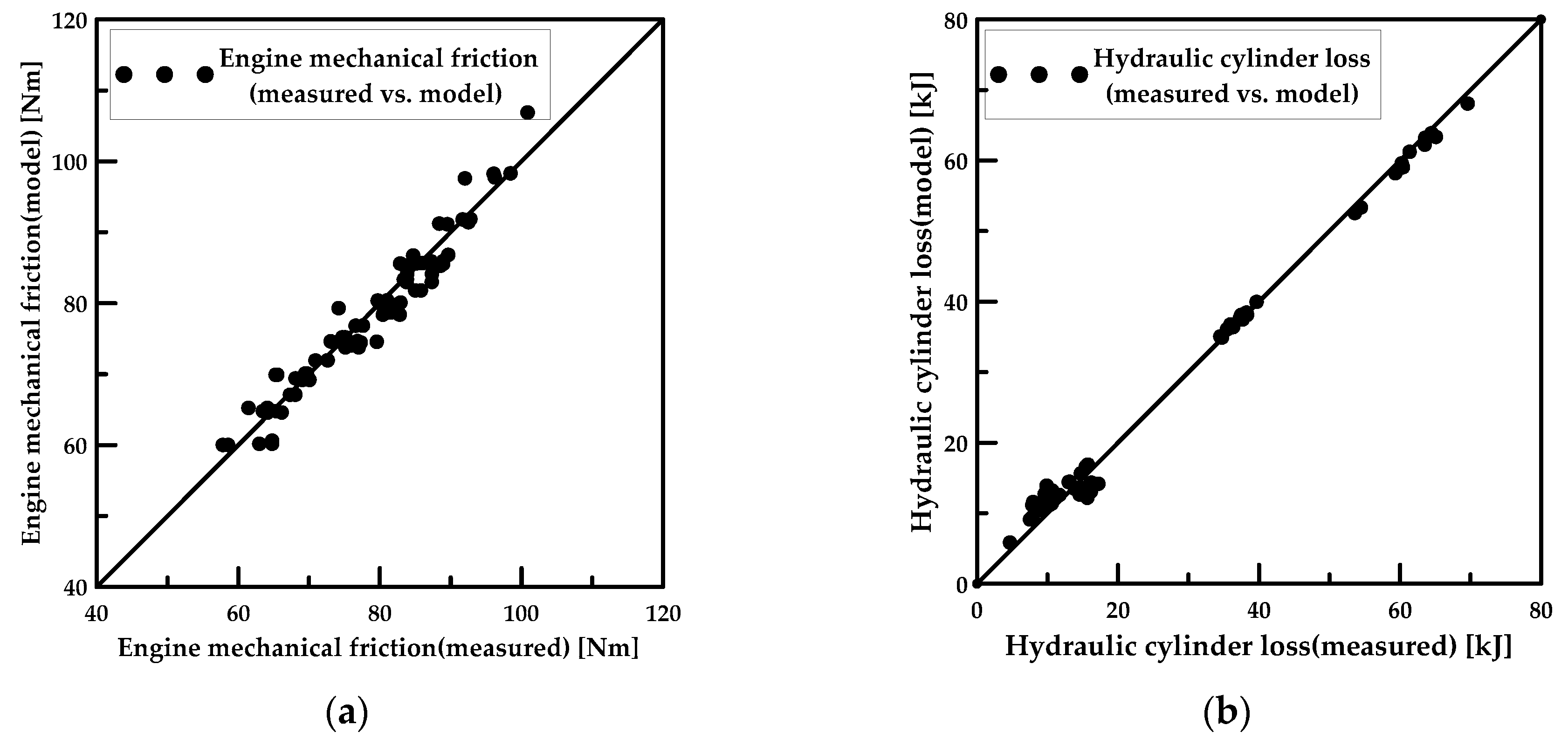
Figure 6 shows the equation for each normalized friction factor. Figure 7a shows the model validation results by comparing the engine mechanical friction model with measurement data measured under various conditions.
The pumping loss, i.e., the loss in engine intake and exhaust, is given by Equation (17).
W p u m p i n g = B D C , e x h a u s t B D C , i n t a k e P c y l   d V c y l
The alternator work is given by Equation (18) using the battery voltage, alternator generating current, and alternator efficiency, considering the system converting mechanical energy into electrical energy through the alternator.
W a l t = V b a t × I a l t d t η a l t
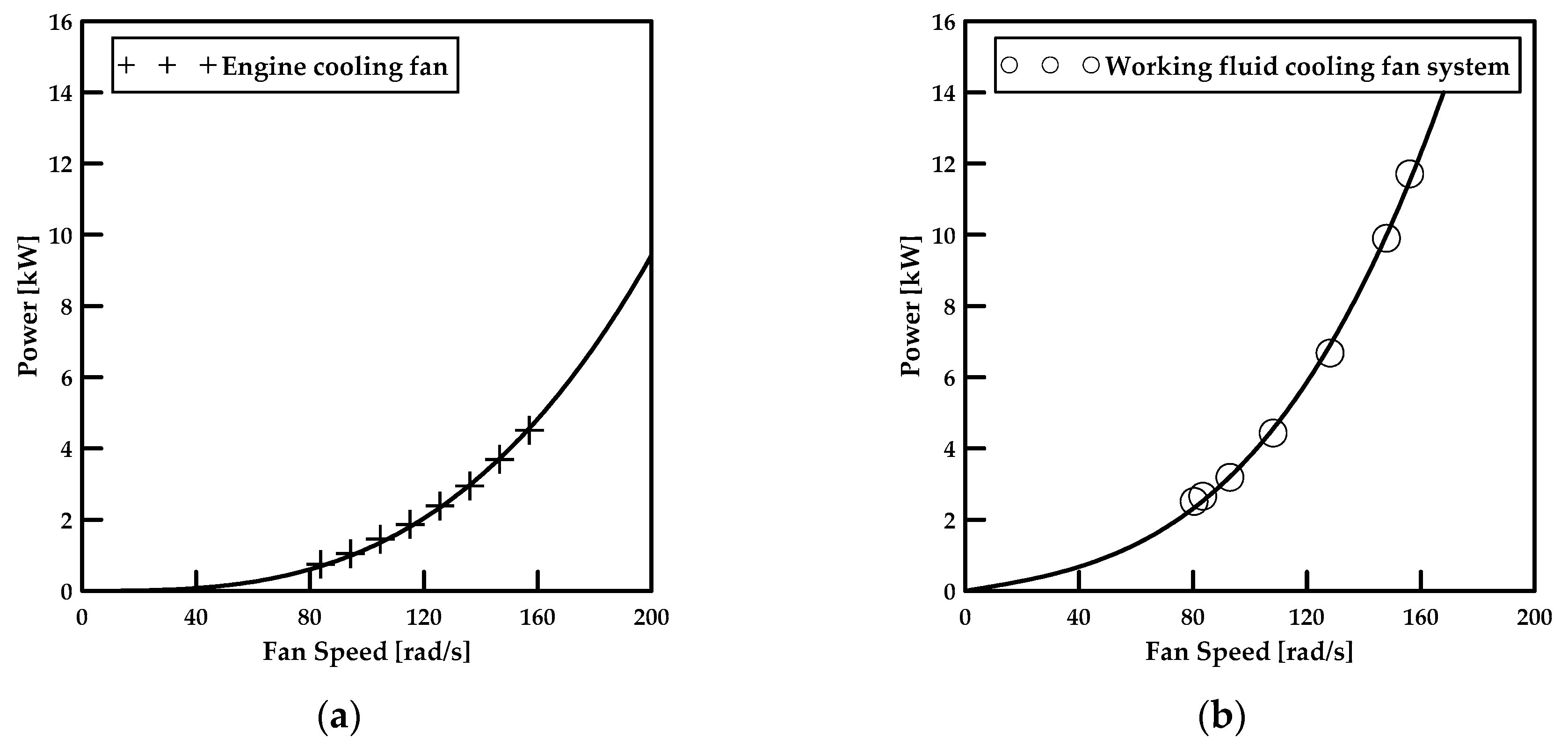
Engine cooling fan work is given by a third degree equation for the operating speed of the fan, as shown in Equation (19). The coefficient of the defined equation is set by simulating the engine cooling system on a dynamometer and measuring the energy consumption, according to the fan speed, as shown in Figure 8a.
W c o o l i n g   f a n = ( 0.00118 ω c o o l i n g   f a n 3 ) × Δ t

3.2. Modeling of the Hydraulic System

Change in viscosity due to the working fluid (hydraulic oil) temperature in the hydraulic system of the excavator is a component affecting the flow loss and friction. Furthermore, most of the energy consumed in the hydraulic system is converted into heat, which increases the temperature of the working fluid [38]. Accordingly, a system is equipped to control the hydraulic fluid temperature by driving the cooling fan through the hydraulic motor. In Section 2.2, the aforementioned cooling system was classified into energy consumption components, and a preliminary experiment was conducted to model them. Like the engine cooling fan, this is given by a third degree equation (Equation (20)), and the related coefficients were set by analyzing the data obtained through the experiment, as shown in Figure 8b.
W w o r k i n g   f l u i d   f a n = ( 0.00249 ω w o r k i n g   f l u i d   f a n 3 + 12.87071 ω w o r k i n g   f l u i d   f a n ) × Δ t
The hydraulic energy transferred to the hydraulic cylinder is balanced with the change in kinetic energy and potential energy of each implement structure, the hydraulic energy acting on the opposite side of the double-acting cylinder, the energy lost in the flow path, cylinder, and implement structure. This is shown in Figure 9a.
The change in kinetic energy and potential energy of the implement structure is given by Equation (21) using the measured real-time cylinder displacement and kinematic model. The output hydraulic energy ( W c y l i n d e r , o u t ) on the opposite side of the double-acting cylinder, or exiting the cylinder, is given by Equation (22) through the pressure and flow rate.
The hydraulic cylinder loss is defined by Equation (23) through the measured input hydraulic energy and output energy, in addition to the calculated change in kinetic energy and potential energy.
W a c t u a t o r = m g Δ h + 1 2 J ω 2 + 1 2 m v 2
W c y l i n d e r , o u t = P c y l i n d e r , o u t × Q ˙ c y l i n d e r , o u t d t
W c y l i n d e r   l o s s = W c y l i n d e r , i n W a c t u a t o r W c y l i n d e r , o u t
The aforementioned equations can be applied in situations where the geometric components of the implement structure are known. For excavators, however, it is difficult to determine the exact state of the excavation target during actual operation, and the mass transported in the bucket cannot be accurately known. As such, the hydraulic cylinder loss is modeled through the aforementioned equation and preliminary experiments. The cylinder hydraulic loss consists of the loss in the flow path, cylinder, and the friction of the implement structure; the flow loss is affected by the flow rate, according to Darcy’s equation (Equation (24)) [39].
H L = f ( L D ) ( v 2 2 g ) + K ( v 2 2 g )
The mechanical friction generated in the implement structure is also a function of speed in the general hydrodynamic lubrication region and can be expressed by a second degree equation. Under these two assumptions, cylinder loss is expressed as a second degree equation for cylinder displacement speed, as shown in Equation (25).
W c y l i n d e r   l o s s = ( c 1 v c y l i n d e r 2 + c 2 v c y l i n d e r + c 3 ) × Δ s
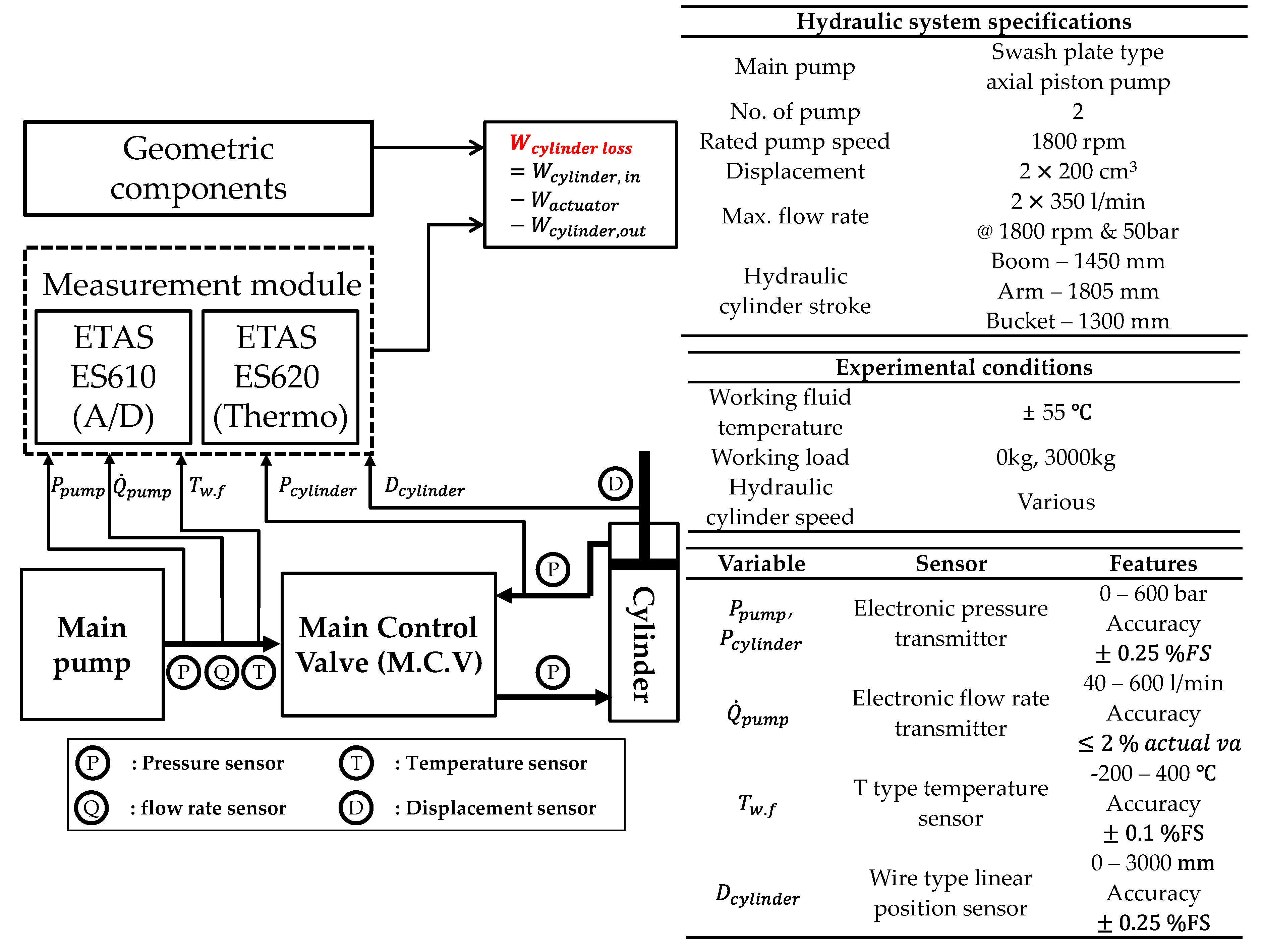
The coefficients in Equation (25) were selected from preliminary experiments. To determine the effect on the load, preliminary experiments added mass to the bucket and operated each cylinder at various speeds. Detailed experiment set up, conditions, and sensor specifications are shown Figure 10. Figure 9b shows the results of applying the previous experimental results to Equations (21)–(23). According to the previous experimental results, the hydraulic cylinder loss had a low influence on the load and a dominant influence on the cylinder displacement speed. The hydraulic cylinder loss model was verified by comparing the hydraulic cylinder loss obtained from Equation (25) and value of Table 2 with the results obtained from Equation (23) during no-load dig and dump operation. The result is shown in Figure 7b.

4. Real Time Data Measurement System

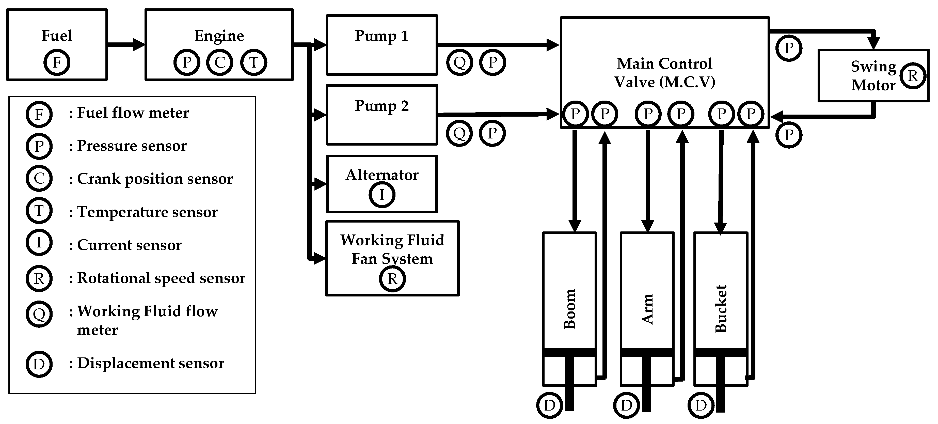
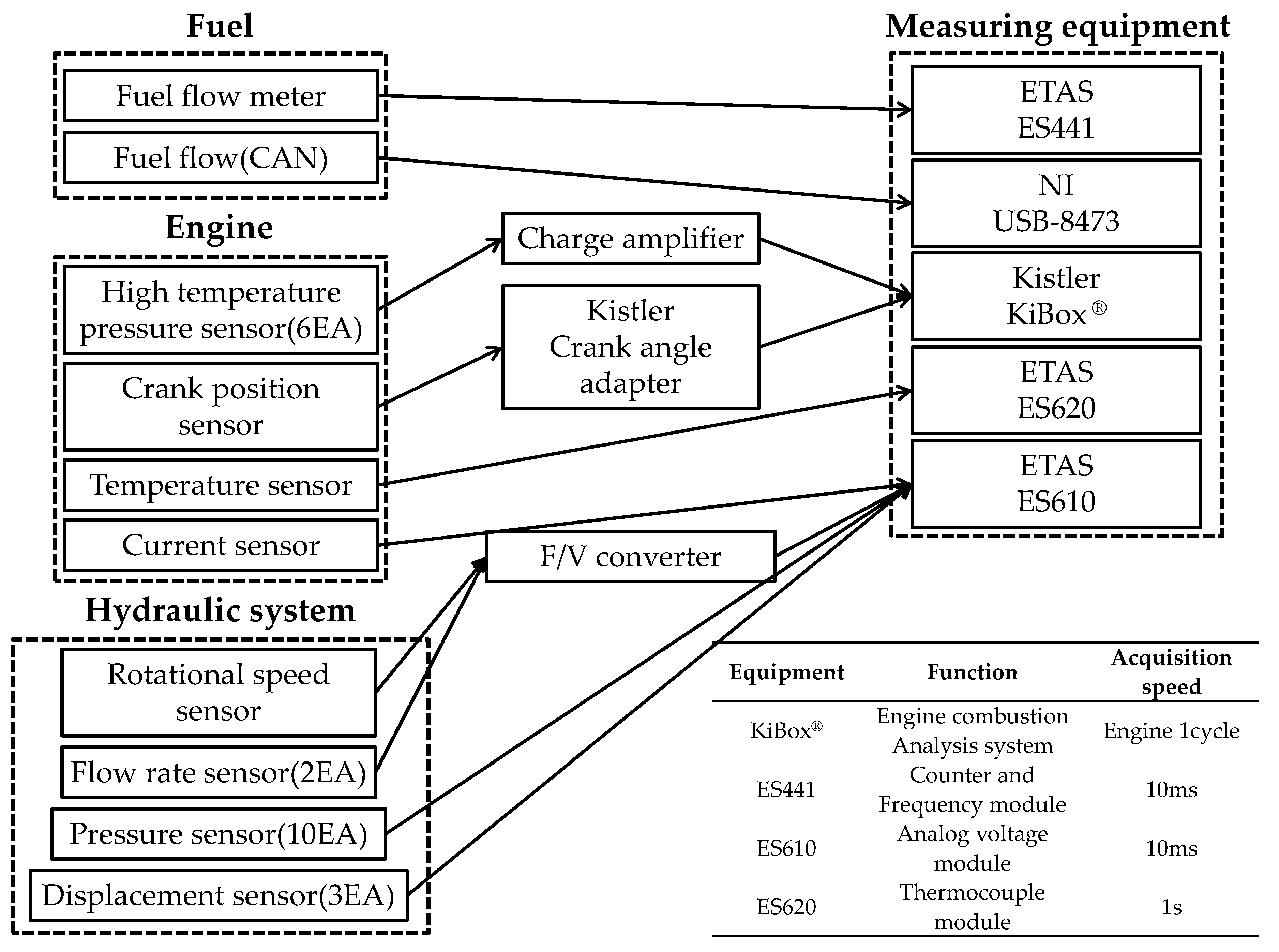
To analyze the energy consumption components identified in the previous section, the real-time measurement system of the excavator was constructed, as shown in Figure 11.
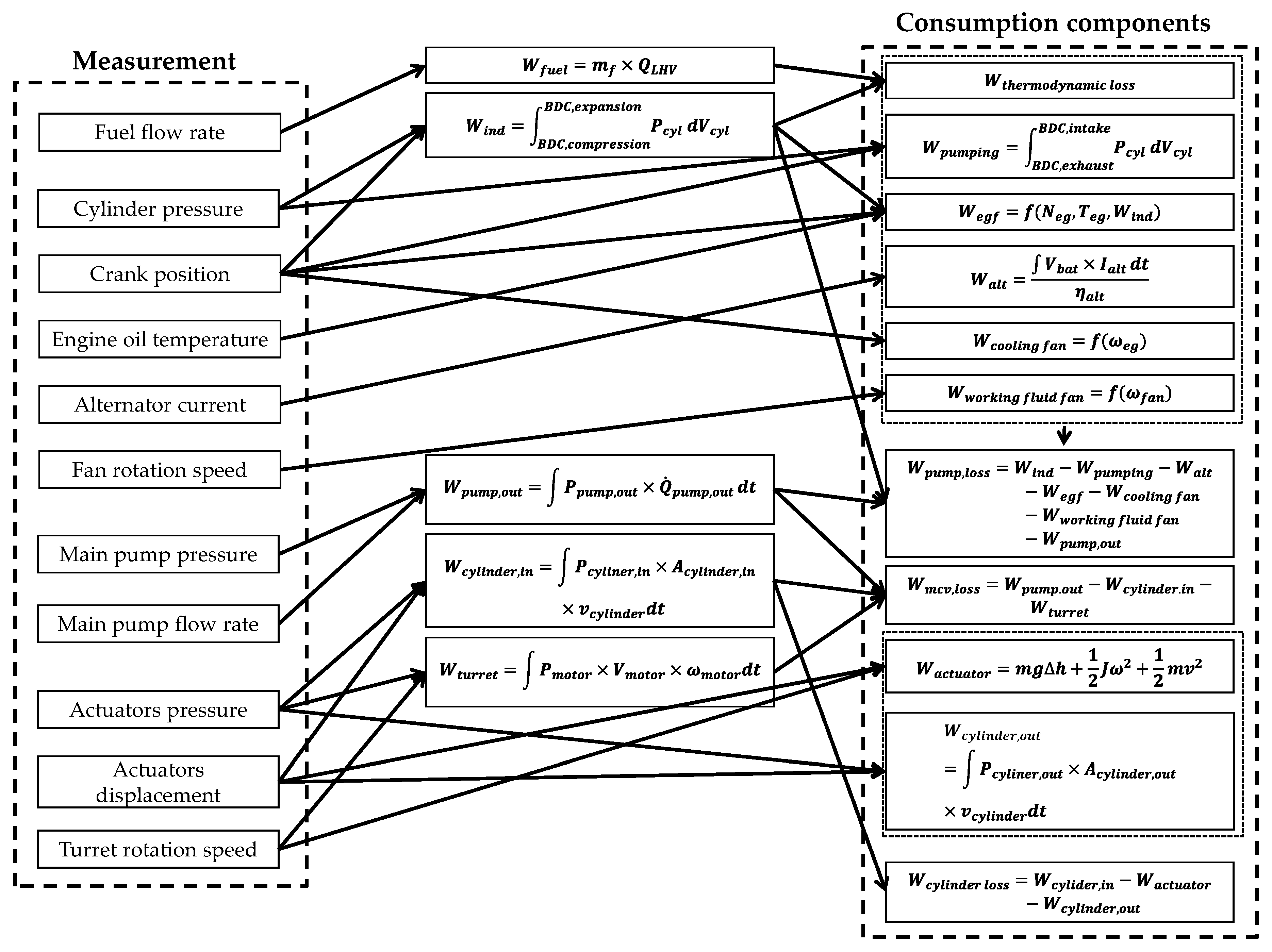
To obtain the indicated work and pumping loss, a combustion pressure sensor is installed in each cylinder, and the crank angle signal is processed to obtain the engine rotation angle and speed. The engine mechanical friction defined through the engine component test requires engine load, engine speed, and engine temperature; for this purpose, an oil temperature sensor is installed in the engine. The speed of the engine fan is calculated using the engine speed (calculated above) because it is connected to the engine speed and pulley. A current sensor is installed in the alternator to measure the real-time current. As the working fluid cooling fan is operated by the hydraulic motor and not connected to the engine and pulley, a rotation speed sensor is installed on the fan blade to measure the fan speed. A pressure sensor and a flowmeter are installed at the outlet of the main pump to determine the pump output hydraulic energy. When installing a flowmeter to directly measure the flow rate after the MCV, the flow resistance is increased, and the installation space is small. As such, it is instead indirectly measured through a cylinder displacement sensor. The flow rate of the swing motor is indirectly measured by the rotational speed of the turret. The sensors and measuring equipment used in the composition of the measurement system are shown in Figure 12. Figure 13 shows the excavator system-based energy flow analysis defined in Section 2 and Section 3 integrated with the measurement system of Section 4.

5. Dig and Dump Cycle Analysis

Excavators perform various tasks according to traveling, digging, dumping, grinding, and numerous additional attachments. Consequently, fixed conditions are required for a variety of tasks to evaluate and analyze actual excavator operation, such as the Japan Construction Mechanization Association Standard (JCMAS) working cycle [40]. Moreover, the proportion of each task in the total workload varies between track excavators and wheel excavators.
For wheel excavators, among the four tasks, the ratio of traveling increases due to the convenience of road driving. For both types of excavators, however, digging and dumping comprise the largest proportions [41].
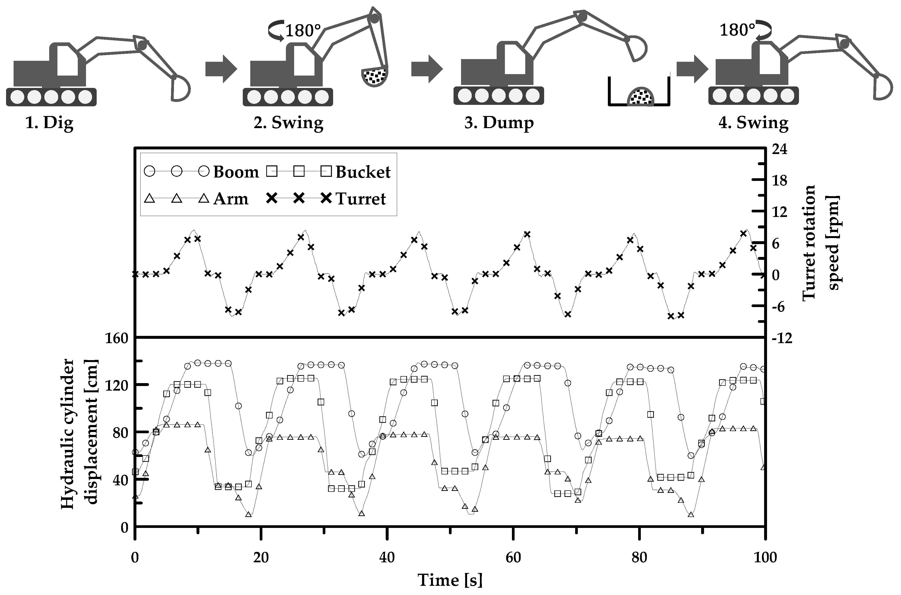
This study first constructs a working cycle that repeatedly performs digging and dumping, excluding traveling and grinding, and performs tests and analyses.
The working cycle attempted to repeatedly operate under the same conditions (temperature, height, speed, etc.) to the extent possible, and the operation sequence of each part was made constant. Figure 14 shows the cycle.
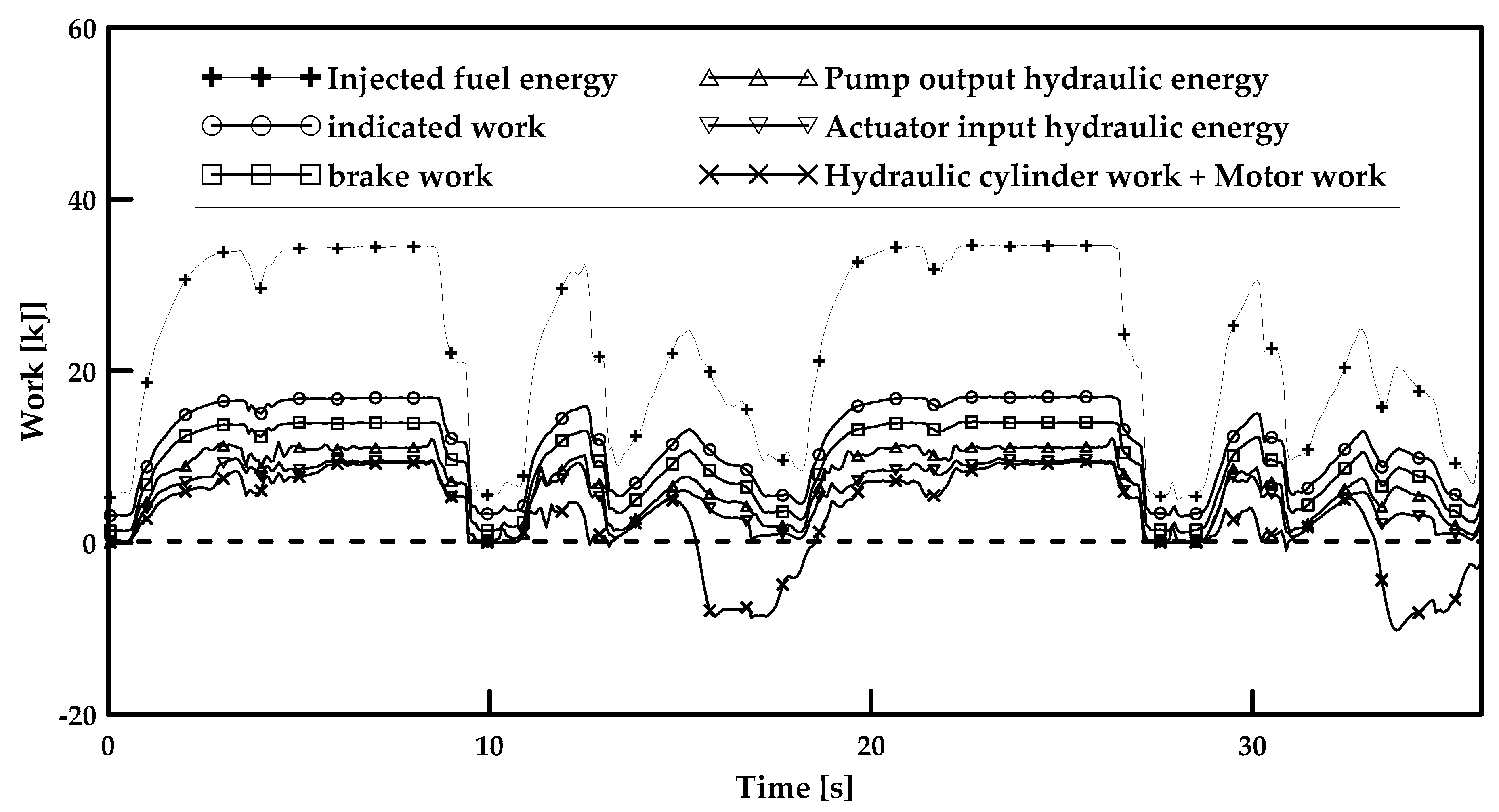
The data measured during the progress of the working cycle were analyzed to examine the energy consumption of each consumption component; the real-time energy consumption during working cycle operation is shown in Figure 15.
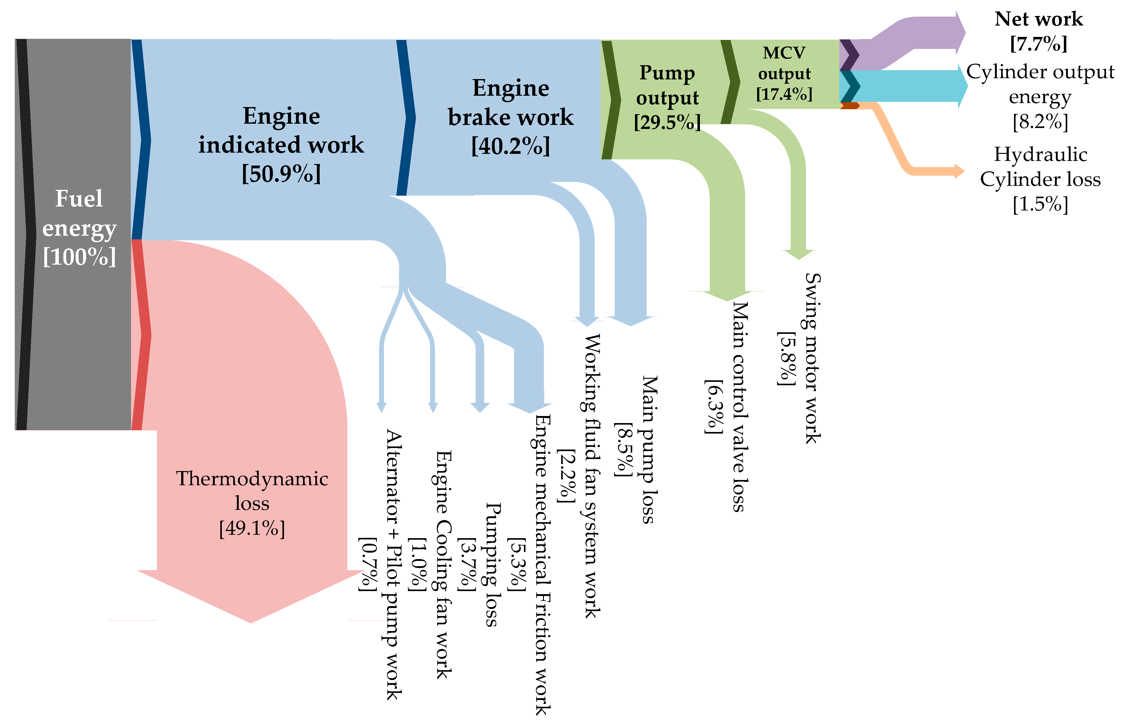
Figure 16 shows the energy consumption characteristics of the entire working cycle. The results of the major system are comparable with those published by other authors. The engine system consumes approximately 60% fuel energy and main pump and the hydraulic auxiliary devices consume more than 10% fuel energy. Only about 10% of fuel energy is used on actual work [34,42].
Detailed energy consumption break down results determined by the methodology proposed in this study are as follows. Among the total consumed fuel, 50.9% was converted to mechanical energy in the engine, among which 25.2% was consumed by engine friction, pumping loss, and various accessory operations before being transferred to the main pump. Next, 22.4% of the mechanical energy transferred to the main pump was consumed by friction and flow loss, and the remaining energy was converted into hydraulic energy and transferred to the MCV. Of the hydraulic energy transferred to the MCV, only 78.4% was transferred to the hydraulic motor and hydraulic cylinders due to pressure and flow rate loss. This corresponds to 23.2% of the total fuel energy and 45.5% of the energy generated by the engine. Furthermore, 47.4% of the hydraulic energy transferred to the hydraulic cylinder was wasted through the cylinder output hydraulic energy, and 8.2% was wasted through the hydraulic cylinder loss. Excluding this, 44.4% of the hydraulic energy is the net work used in actual work, which is 7.7% of the total fuel energy, 15.1% of the energy generated by the engine, and 26.1% of the hydraulic energy converted in the pump.
The hydraulic cylinder operations, which transfer 17.4% of the total fuel energy, are classified into items, according to the actuator cylinder energy balance defined in Section 3.2 (Table 3).
The most energy-consuming operation of the hydraulic cylinder operations was boom, which consumed approximately 1.8 times more energy than arm (4.5%) and bucket (4.7%) operations. This is due to the difference caused by the discharged cylinder output hydraulic energy that could not be recovered, rather than the difference due to the net work.

6. Conclusions

To establish the energy flow-down method of an excavator, this study classified the entire excavator system into the engine system, hydraulic system, and hydraulic actuation systems to identify the energy consumption components for each part. The identified energy consumption components were divided into those that can be determined through actual measurements and those that can be determined through additional modeling. The analysis methodology was established for each of these components. In particular, the mechanical friction of the engine, cooling fan, hydraulic cylinder loss, and components that require additional modeling were established by designing and conducting an experimental procedure based on theoretical modeling. A measurement system is required to collect data for each analysis of the energy consumption component in real time. Therefore, in this study, a real-time integrated measurement system that is capable of measuring pressure, flow rate, temperature, and speed was built. The real-time energy flow-down methodology of the excavators was presented through the analysis methodology of each energy consumption component and the real-time measurement system.
To apply the proposed methodology for the energy consumption analysis of an actual excavator, this study established a basic working cycle that simulates dig and dump operations, which account for a large proportion of excavator operations. The working cycle was performed repeatedly and analyzed according to the energy consumption components identified in the methodology. According to the results, of the total fuel energy, 49.1% was consumed by thermodynamic loss, 10.7% by engine total friction work, and 17% in the hydraulic system; excluding this, 23.2% was used for operating actuators. Among this, 5.8% of the total fuel energy was used in the hydraulic motor, and 7.7% of the energy was transferred to hydraulic cylinders and used for the net work.
By applying the proposed energy flow-down methodology to various working cycles and operating modes and by analyzing the energy consumption characteristics of the entire excavator system, it will be possible to estimate the fuel efficiency improvement margin under various conditions. This will also facilitate the comparison and analysis of the energy consumption characteristics of individual excavators under identical conditions.

Author Contributions

The contribution of the authors is summarized as follows: Conceptualization, J.P. and J.L.; methodology, J.P. and K.A.; software, K.A.; data curation, K.A., H.K. and Y.A.; writing—review and editing, K.A., J.P. and J.L. All authors have read and agreed to the published version of the manuscript.

Funding

This research received no external funding.

Conflicts of Interest

The authors declare no conflict of interest.

References

  1. Trani, M.L.; Bossi, B.; Gangolells, M.; Casals, M. Predicting fuel energy consumption during earthworks. J. Clean. Prod. 2016, 112, 3798–3809. [Google Scholar] [CrossRef]
  2. Abekawa, T.; Tanikawa, Y.; Hirosawa, A. Introduction of Komatsu Genuine Hydraulic Oil KOMHYDRO HE; Komatsu Technical Report; Yumpu: Komatsu, Japan, 2010; Volume 56. [Google Scholar]
  3. Ohira, S.; Suehiro, M.; Ota, K.; Kawamura, K. Use of emission rights for construction machinery to help prevent global warming. Hitachi Rev. 2013, 62, 123–130. [Google Scholar]
  4. Han, H.; Lee, D.; Lee, J.; Park, J.; Park, K. Analysis of the fuel economy factor of the commercial vehicle. In Proceedings of the KSAE 2005 Annual Conference and Exhibition, Pyeongtaek, Korea, 24–26 November 2005; pp. 522–526. [Google Scholar]
  5. Filla, R. Quantifying Operability of Working Machines. Ph.D. Thesis, Linköping University, Linköping, Sweden, 2011. [Google Scholar]
  6. Filla, R. Operator and Machine Models for Dynamic Simulation of Construction Machinery. Ph.D. Thesis, Linköping University, Linköping, Sweden, 2005. [Google Scholar]
  7. Yang, J.; Quan, L.; Yang, Y. Excavator energy-saving efficiency based on diesel engine cylinder deactivation technology. Chin. J. Mech. Eng. 2012, 25, 897–904. [Google Scholar] [CrossRef]
  8. Xu-dong, F. Analysis and Computing of Load Sensing System in Hydraulic Excavator. J. Tongji Univ. 2001, 29, 1097–1100. [Google Scholar]
  9. Joo, C.; Stangl, M. Application of power regenerative boom system to excavator. In Proceedings of the 10th International Fluid Power Conference, Dresden, Germany, 8–10 March 2016; pp. 175–184. [Google Scholar]
  10. Choi, K.; Seo, J.; Nam, Y.; Kim, K.U. Energy-saving in excavators with application of independent metering valve. J. Mech. Sci. Technol. 2015, 29, 387–395. [Google Scholar] [CrossRef]
  11. Williamson, C. Power Management for Multi Actuator Mobile Machines with Displacement Controlled Hydraulic Actuators. Ph.D. Thesis, Purdue University, West Lafayette, IL, USA, 2010. [Google Scholar]
  12. Ge, L.; Dong, Z.; Quan, L.; Li, Y. Potential energy regeneration method and its engineering applications in large-scale excavators. Energy Convers Manag. 2019, 195, 1309–1318. [Google Scholar] [CrossRef]
  13. Kim, Y.; Kim, P.; Murrenhoff, H. Boom potential energy regeneration scheme for hydraulic excavators. In Proceedings of the ASME/BATH 2016 Symposium on Fluid power and Motion Control, Bath, UK, 7–9 September 2016. [Google Scholar]
  14. Zhao, P.; Chen, Y.; Zhou, H. Simulation analysis of potential energy recovery system of hydraulic hybrid excavator. Int. J. Pr. Eng. Man. 2017, 18, 1575–1589. [Google Scholar] [CrossRef]
  15. Wang, T.; Wang, Q. Design and analysis of compound potential energy regeneration system for hybrid hydraulic excavator. Proc. Inst. Mech. Eng. I 2012, 226, 1323–1334. [Google Scholar] [CrossRef]
  16. Xiao, Q.; Wang, Q.; Zhang, Y. Control strategies of power system in hybrid hydraulic excavator. Autom. Constr. 2008, 4, 361–367. [Google Scholar] [CrossRef]
  17. Lee, D.; Kim, N.; Seo, H.; Cha, S.; Lim, W. Fuel consumption analysis of hybrid excavator using electric swing motor. In Proceedings of the 24th International Battery, Hybrid and Fuel Cell Electric Vehicle Symposium and Exhibition, Stavanger, Norway, 13–16 May 2009; pp. 879–886. [Google Scholar]
  18. Kagoshima, M.; Sora, T.; Komiyama, M. Development of hybrid power train control system for excavator. In Proceedings of the JSAE Annual Congress, Yokohama, Japan, 21–23 May 2003; pp. 1–6. [Google Scholar]
  19. Tsutsui, A.; Nanjyo, T.; Yoshimatsu, T. Development of the electro hydraulic actuator system on hybrid excavator. In Proceedings of the JSAE Annual Congress, Yokohama, Japan, 21–23 May 2003; pp. 7–12. [Google Scholar]
  20. Shen, W.; Jiang, J.; Su, X.; Karimi, H.R. Energy-saving analysis of hydraulic hybrid excavator based on common pressure rail. Sci. World J. 2013, 2013, 1–12. [Google Scholar] [CrossRef] [PubMed]
  21. Hippalgaonkar, R.; Ivantysynova, M.; Zimmerman, J. Fuel-savings of a Mini-excavator through a hydraulic hybrid displacement controlled system. In Proceedings of the 8th international fluid power conference, Dresden, Germany, 26–28 March 2012; pp. 139–153. [Google Scholar]
  22. Hippalgaonkar, R.; Ivantysynova, M. A Series-Parallel Hydraulic Hybrid Mini-Excavator with Displacement Controlled Actuators. In Proceedings of the 13th Scandinavian International Conference on Fluid Power, Linköping, Sweden, 3–5 June 2013; pp. 31–42. [Google Scholar]
  23. Hippalgaonkar, R. Power Management for Hydraulic Hybrid Multi-Actuator Mobile Machines with DC Actuators. Ph.D. Thesis, Purdue University, West Lafayette, IL, USA, 2014. [Google Scholar]
  24. Hippalgaonkar, R.; Ivantysynova, M. Optimal power management of hydraulic hybrid mobile machines—Part I: Theoretical studies, modeling and simulation. J. Dyn. Syst. Meas. Control. 2016, 138, 051002. [Google Scholar] [CrossRef]
  25. Minav, T.; Heikkinen, J.E.; Pietola, M. Direct driven hydraulic drive for new powertrain topologies for non-road mobile machinery. Electr. Power Syst. Res. 2017, 152, 390–400. [Google Scholar] [CrossRef]
  26. Minav, T.; Bonato, C.; Sainio, P.; Pietola, M. Direct driven hydraulic drive. In Proceedings of the 9th International Fluid Power Conference (IFK), Aachen, Germany, 24–26 March 2014. [Google Scholar]
  27. Minav, T.; Bonato, C.; Sainio, P.; Pietola, M. Efficiency of direct driven hydraulic drive for non-road mobile working machines. In Proceedings of the 2014 International Conference on Electrical Machines (ICEM), Berlin, Germany, 2–5 September 2014; pp. 2431–2435. [Google Scholar]
  28. Zhang, S.; Minav, T.; Pietola, M. Decentralized Hydraulics for Micro Excavator. In Proceedings of the 15th Scandinavian International Conference on Fluid Power, Linköping, Sweden, 7–9 June 2017; pp. 187–195. [Google Scholar]
  29. Zimmerman, J.D.; Pelosi, M.; Williamson, C.A. Energy consumption of an LS excavator hydraulic system. In Proceedings of the ASME international mechanical engineering congress and exposition, Seattle, WA, USA, 11–15 November 2007; pp. 117–126. [Google Scholar]
  30. Casoli, P.; Riccò, L.; Campanini, F.; Lettini, A.; Dolcin, C. Mathematical model of a hydraulic excavator for fuel consumption predictions. In Proceedings of the ASME/BATH 2015 symposium on Fluid Power and Motion Control, Chicago, IL, USA, 12–14 October 2015. [Google Scholar]
  31. Altare, G.; Padovani, D.; Nervegna, N. A Commercial Excavator: Analysis, Modelling and Simulation of the Hydraulic Circuit. In Proceedings of the SAE 2012 Commercial Vehicle Engineering congress, Rosemont, IL, USA, 13–14 September 2012. [Google Scholar]
  32. Casoli, P.; Riccò, L.; Campanini, F.; Bedotti, A. Hydraulic hybrid excavator—Mathematical model validation and energy analysis. Energies 2016, 9, 1002. [Google Scholar] [CrossRef] [Green Version]
  33. Bedotti, A.; Campanini, F.; Pastori, M.; Riccò, L.; Casoli, P. Energy saving solutions for a hydraulic excavator. Energy Procedia 2017, 126, 1099–1106. [Google Scholar] [CrossRef]
  34. Vukovic, M.; Leifeld, R.; Murrenhoff, H. Reducing fuel consumption in hydraulic excavators—A comprehensive analysis. Energies 2017, 10, 687. [Google Scholar] [CrossRef] [Green Version]
  35. Kang, J.; Choi, J.; Lee, J.; Lee, C.; Ko, S.; Lee, D. A platform study of fuel consumption measurements for an excavator in motion. J. Drive Control 2017, 14, 35–40. [Google Scholar]
  36. Heywood, J.B. Internal Combustion Engine Fundamentals, 1st ed.; McGraw-Hill: New York City, NY, USA, 1988; pp. 42–59, 712–745. [Google Scholar]
  37. Stotsky, A. Adaptive estimation of the engine friction torque. Eur. J. Control 2007, 13, 618–624. [Google Scholar] [CrossRef]
  38. Zimmerman, J.; Busquets, E.; Ivantysynova, M. 40% Fuel Savings by Displacement Control Leads to Lower Working Temperatures-A Simulation Study and Measurements. In Proceedings of the 52nd National Conference on Fluid Power, Las Vegas, NV, USA, 23–25 March 2011; pp. 693–701. [Google Scholar]
  39. Esposito, A. Fluid Power with Application, 7th ed.; Pearson Education: Upper saddle River, NJ, USA, 2009; pp. 117–141. [Google Scholar]
  40. Earth-Moving Machinery—Fuel Consumption on Hydraulic Excavator—Test Procedure; JCMAS H020:2007; Japan Construction Machinery and Construction Association for Hydraulic Excavators: Tokyo, Japan, 2007.
  41. Fecke, M. Standardisierung definierter Lastzyklen und Messmethoden zur Energieverbrauchsermittlung von Baumaschinen. In Proceedings of the 5th Fachtgaung Baumaschinentechnik, Dresden, Germany, 17–19 September 2015. [Google Scholar]
  42. Sturm, C. Bewertung der Energieeffizienz von Antriebssystemen mobiler Arbeitsmaschinen am Beispiel Bagger. Ph.D. Thesis, Karlsruhe Institute of Technology, Karlsruhe, Germany, 2015. [Google Scholar]
Figure 1. Excavator system.
Energies 13 00951 g001
Figure 2. Energy flow model in the engine system.
Energies 13 00951 g002
Figure 3. Energy flow model in the hydraulic system.
Energies 13 00951 g003
Figure 4. Energy flow model in the hydraulic actuation system.
Energies 13 00951 g004
Figure 5. Engine bench test set up and specification.
Energies 13 00951 g005
Figure 6. Normalized friction factor. (a) Engine oil temperature; (b) engine speed; (c) engine load.
Energies 13 00951 g006aEnergies 13 00951 g006b
Figure 7. Measurement data vs. model. (a) Engine mechanical friction; (b) hydraulic cylinder loss.
Energies 13 00951 g007
Figure 8. Result of the cooling fan test. (a) Engine cooling fan; (b) working fluid cooling fan system.
Energies 13 00951 g008
Figure 9. (a) Actuator cylinder energy balance; (b) result of the hydraulic cylinder loss test.
Energies 13 00951 g009
Figure 10. Hydraulic cylinder experiment set up and specification.
Energies 13 00951 g010
Figure 11. Real time data measurement system.
Energies 13 00951 g011
Figure 12. Sensor and measuring equipment.
Energies 13 00951 g012
Figure 13. Energy flow-down methodology.
Energies 13 00951 g013
Figure 14. Dig and dump working cycle.
Energies 13 00951 g014
Figure 15. Real time energy consumption analysis.
Energies 13 00951 g015
Figure 16. Energy flow during dig and dump.
Energies 13 00951 g016
Table 1. Nomenclature.
SymbolDefinitionUnitSymbolDefinitionUnit
C L Normalized friction factor for engine load- W c y l i n d e r , o u t Hydraulic cylinder output energyJ
C N Normalized friction factor for engine speed- W e g f Engine mechanical friction workJ
C T Normalized friction factor for temperature- W e g f , base Engine mechanical friction work
at base point
J
I a l t Alternator currentA W e n g i n e   t o t a l   f r i c t i o n Engine total
Friction work
J
m f Fuel masskg W h y d r a u l i c   c y l i n d e r Hydraulic cylinder input energyJ
P c y l Engine cylinder pressurePa W h y d r a u l i c   m o t o r Hydraulic motor
input energy
J
P c y l i n d e r Hydraulic cylinder pressurePa W i n d . g r o s s Gross indicated workJ
P m o t o r Hydraulic motor pressurePa W M C V   l o s s MCV lossJ
P p u m p Main pump pressurePa W M C V , o u t MCV output energyJ
Q ˙ c y l i n d e r   c y l . Hydraulic cylinder
flow rate
m3/s W p u m p i n g Pumping lossJ
Q L H V Low heating valueJ/kg W p u m p , i n Main pump
input work
J
Q ˙ m o t o r Hydraulic motor
flow rate
m3/s W p u m p ,   o u t Main pump
output energy
J
Q ˙ p u m p , Main pump flow ratem3/s W p u m p   l o s s Main pump lossJ
v c y l i n d e r Hydraulic cylinder displacement speedcm/s W t h e r m o d y n a m i c   l o s s Thermodynamic lossJ
V bat Battery voltageV W w o r k i n g   f l u i d   f a n Working fluid fan system workJ
V c y l Engine cylinder volumem3 η alt Alternator efficiency-
W a l t Alternator workJ ω c o o l i n g   f a n Cooling fan
angular velocity
rad/s
W b r a k e Engine brake workJ ω w o r k i n g   f l u i d   f a n Working fluid fan
angular velocity
rad/s
W c o o l i n g   f a n Cooling fan workJ Δ t Times
W c y l i n d e r   l o s s Hydraulic
cylinder loss
J Δ s Hydraulic cylinder displacementm
Table 2. Values of the coefficients c1, c2, and c3.
Actuatorc1c2c3
Boom11.04173.466371.11
Arm7.4588.053229.47
Bucket17.11111.784970.35
Table 3. Hydraulic cylinder energy flow during dig and dump.
Consumption
Component
BoomArmBucket
Fuel Energy(%)Fuel Energy(%)Fuel Energy(%)
Net work2.1%(24.9%)3.2%(72.2%)2.4%(50.0%)
Cyl. out energy5.7%(70.9%)0.9%(21.0%)1.6%(34.0%)
Hyd. cylinder loss0.4%(4.2%)0.3%(6.8%)0.8%(16.0%)
Total8.2%-4.5%-4.7%-