Article

A Geothermal-Solar Hybrid Power Plant with Thermal Energy Storage

by
Brady Bokelman
1,
Efstathios E. Michaelides
1,* and
Dimitrios N. Michaelides
2
1
Department of Engineering, TCU, Fort Worth, TX 76132, USA
2
Department of Engineering Physics, University of Wisconsin, Madison, 53706 WI, USA
*
Author to whom correspondence should be addressed.
Energies 2020, 13(5), 1018; https://doi.org/10.3390/en13051018
Submission received: 4 February 2020 / Revised: 20 February 2020 / Accepted: 21 February 2020 / Published: 25 February 2020

Abstract

:
The concept of a geothermal-solar power plant is proposed that provides dispatchable power to the local electricity grid. The power plant generates significantly more power in the late afternoon and early evening hours of the summer, when air-conditioning use is high and peak power is demanded. The unit operates in two modes: (a) as a binary geothermal power plant utilizing a subcritical Organic Rankine Cycle; and (b) as a hybrid geothermal-solar power plant utilizing a supercritical cycle with solar-supplied superheat. Thermal storage allows for continuous power generation in the early evening hours. The switch to the second mode and the addition of solar energy into the cycle increases the electric power generated by a large factor—2 to 9 times—during peak power demand at a higher efficiency (16.8%). The constant supply of geothermal brine and heat storage in molten salts enables this power plant to produce dispatchable power in its two modes of operation with an exergetic efficiency higher than 30%.

1. Introduction

The rate of heat flow from the core to the surface of the earth is 44 TW (44*1012 W). Of this, approximately 30 TW is generated by the decay of radioactive elements in the core and the rest is sensible heat, which indicates that the interior of the earth continuously cools. The cooling process is taking place in geological time scales—on the order of billions of years—and is not expected to influence the temperature of the geothermal resources in the next few millennia. Because of this, geothermal energy is considered a renewable energy source, which is continuously available to satisfy the global energy demand [1]. Unlike solar, which is a periodically variable energy source, and wind power, which is an intermittent energy source, geothermal energy is continuously available. Geothermal power plants around the globe continuously generate electricity, which is dispatched to satisfy the growing global electricity demand. This feature, combined with the low cost of power production, makes geothermal resources attractive to corporations that increasingly add geothermal power plants in their production mix [2,3].
With some exceptions in unexplored regions of volcanic countries, most of the prime high-temperature, high-enthalpy geothermal resources have been utilized globally. With the improvement of geothermal technology and the development of Organic Rankine Cycles (ORCs), lower temperature resources may be now utilized for the production of electricity. The ORC power units account for most of the geothermal power growth [4]. In addition to their higher thermal efficiency and better exergy utilization than the flashing units, the ORC power plants avoid some of the environmental impacts of geothermal energy, most notably the emission of non-condensable gases [5].
The atmospheric CO2 accumulation and the associated Global Climate Change (GCC) necessitate the increasing use of non-fossil energy sources for the production of electricity. In order to avoid GCC, nuclear and renewable (including geothermal) energy sources should supply a high fraction of the global electric power in the future. However, wind and solar power—the most abundant renewable energy sources—are not continuously available to satisfy the fluctuating electric power demand. The higher penetration of these renewable energy sources in the electric production mix induces temporary imbalances in the demand and supply of electricity, which is demonstrated in the called U-shaped demand curves or duck curves [6,7]. When the market penetration of the renewables exceeds approximately 25% of the annual electric energy produced, the augmentation and time-shift of electric power demand exacerbates the supply–demand imbalance. Figure 1 shows the electric power demand in North-Central Texas on a typical summer day (July 21, 2016). The electric power demand is currently satisfied by a group of natural gas, coal, nuclear, and wind power plants, with very small solar input. The significant hump in the afternoon and early evening hours is primarily due to air-conditioning [8]. The Figure also depicts what would be the electricity demand generated by the other sources if a fraction (15%, 25% and 35%) of the annual electric energy output were obtained from solar energy. It is apparent that the non-solar power units would have to limit their power supply during the morning hours, when solar irradiance is high, but the electric power demand is not. This places severe constraints on the base-load units, especially on the nuclear and coal units, which currently supply approximately 400 MW to the region and for which adjustment of power output at short timescales is very inefficient or impossible [1,9].
One may address the duck curve problem by taking advantage of the continuous availability of geothermal energy as well as the availability of high solar irradiance at the periods of the peak electric power demand; and by developing geothermal-solar hybrid power plants that would produce significantly more electric power during the hours of peak electric demand. A recent US patent [10] utilizes a photovoltaic (PV) system to produce solar power—when this is available—and adjusts the flow of the geothermal fluid to maintain constant plant power output. While this system partly utilizes solar energy, it does not produce additional power in the late afternoon and early evening hours, when the power demand is maximum. As it may be seen with the duck curve in Figure 1, and because of the thermal inertia of the air-conditioned buildings, the power peak occurs between 4:00 and 5:00 in the afternoon. At that time, the solar irradiance has peaked and the power from PVs is waning. On the contrary, a great deal of power is not needed during the morning hours (e.g., 9:00 to 12:00), when solar irradiance peaks and causes the dip in the duck curve.
This paper presents the analysis of such a hybrid power plant that operates in two modes:
(a)
A purely ORC geothermal mode during the hours of lower electric power demand.
(b)
A hybrid ORC geothermal-solar mode with thermal energy storage, which is converted to electricity during the higher electric power demand of the late afternoon hours.
The two-mode operation allows the power plant to continuously utilize the brine from the geothermal well(s) and to utilize solar irradiance to significantly increase its output during the high electric demand hours.
It must be noted that the advantages of hybrid-geothermal power plants have been touted since the early years of geothermal power utilization [2,11]. Lenz and Almanza [12] proposed a solar-geothermal hybrid addition to an existing flashing unit at the Cerro Prieto geothermal field in Mexico. The study used parabolic collectors to increase the mass flow rate of the produced vapor and generate more power during peak hours. Because of the salinity of the produced brine, the authors limited their study to the production of only 10% additional vapor. Greenhut et al. [13] presented the concept of hybrid solar-geothermal power plants that integrates solar energy into supercritical ORCs operating with R-134a and flash systems. Solar collectors raise the temperature of the working fluid before it enters the turbines, thereby increasing the exergy of the working fluid and the power to the turbines. The authors concluded that the high-cost solar energy should be used only to raise the temperature of the working fluid above the feasible temperature attained by the geothermal resource.
Because solar irradiance is intermittent, thermal energy storage systems are necessary for the reliable generation of power. A large number of analytical and numerical studies cover this topic. Among them Zhou et al. [14] conducted an analytical study on the effects of superheating the vapor of ORCs using solar energy to counteract the diurnal temperature fluctuations. The study pertains to power plants with low-temperature geothermal resources and air-cooling systems, where diurnal temperature fluctuations account for very high variability of the power output. Yang et al. [15] conducted a simulation of an ORC with solar energy input and determined that cycle superheat increases significantly the efficiency of the cycles for all the working fluids. The off-design performance of solar organic cycles with energy storage was examined by Kutlu et al. [16] who matched electric power demand and supply using a thermal storage system. The performance of solar-powered ORC cycles fitted with a heat storage system was simulated by Manfrida et al. [17] who simulated the performance of power generation for one week. They determined that such cycles could provide electric power for 78.5% of the time, with thermal efficiencies close to 13%.
Ayub et al. [18] examined the economic feasibility of a geothermal-solar power plant with 7% solar share. When optimized the power unit results in an approximately 8% reduction in the life-cycle costs and the combined solar-geothermal hybrid units demonstrate several advantages over individual solar and geothermal systems. The complementary nature of solar and geothermal energy sources has also been considered for the development of hybrid systems that would be used in large buildings [19]. Another study [20] examined the exergetic efficiency of a multigenerational system that would produce electric power, space heating, hot water, air-conditioning and heat for industrial use. A more recent study by McTigue et al. [21] used concentrated solar power for a hybrid solar-geothermal power plant that generates dispatchable power and uses a flashing system. It must be noted that a geothermal unit supplemented with both PV and thermal solar (conventional solar power) is in operation in Stillwater, Nevada, USA [22]. Most of the studies on hybrid systems pertain to geothermal-solar units that use PV for the production of excess electric power during the peak demand period or use the geothermal fluid for heating, while [18] uses a subcritical ORC cycle with very limited superheat.
It is well known that supercritical ORCs are significantly more efficient. However, geothermal supercritical ORCs without superheat expand well-inside the two-phase region and damage the turbine blades. Superheating of the supercritical ORCs alleviates this problem. In addition, superheated geothermal ORCs attain higher temperatures, and the organic fluid attains significantly higher exergy that produces additional power. When the solar heat is added at the higher temperatures (after the preheating by the geothermal fluid), more of the high exergy of solar irradiance is utilized in the cycle. This study pertains to a hybrid geothermal-solar power plant that operates in two modes and utilizes a supercritical ORC with solar superheat to take advantage of a higher temperature supercritical thermodynamic cycle that does not have the limitations of common supercritical cycles without superheat. Limited thermal energy storage is utilized for the short-term generation of electric power during hours of high electricity demand. The main advantages of this system are:
  • The proposed unit generates renewable power that may be contracted and dispatched and avoids the adverse effects of the duck curve.
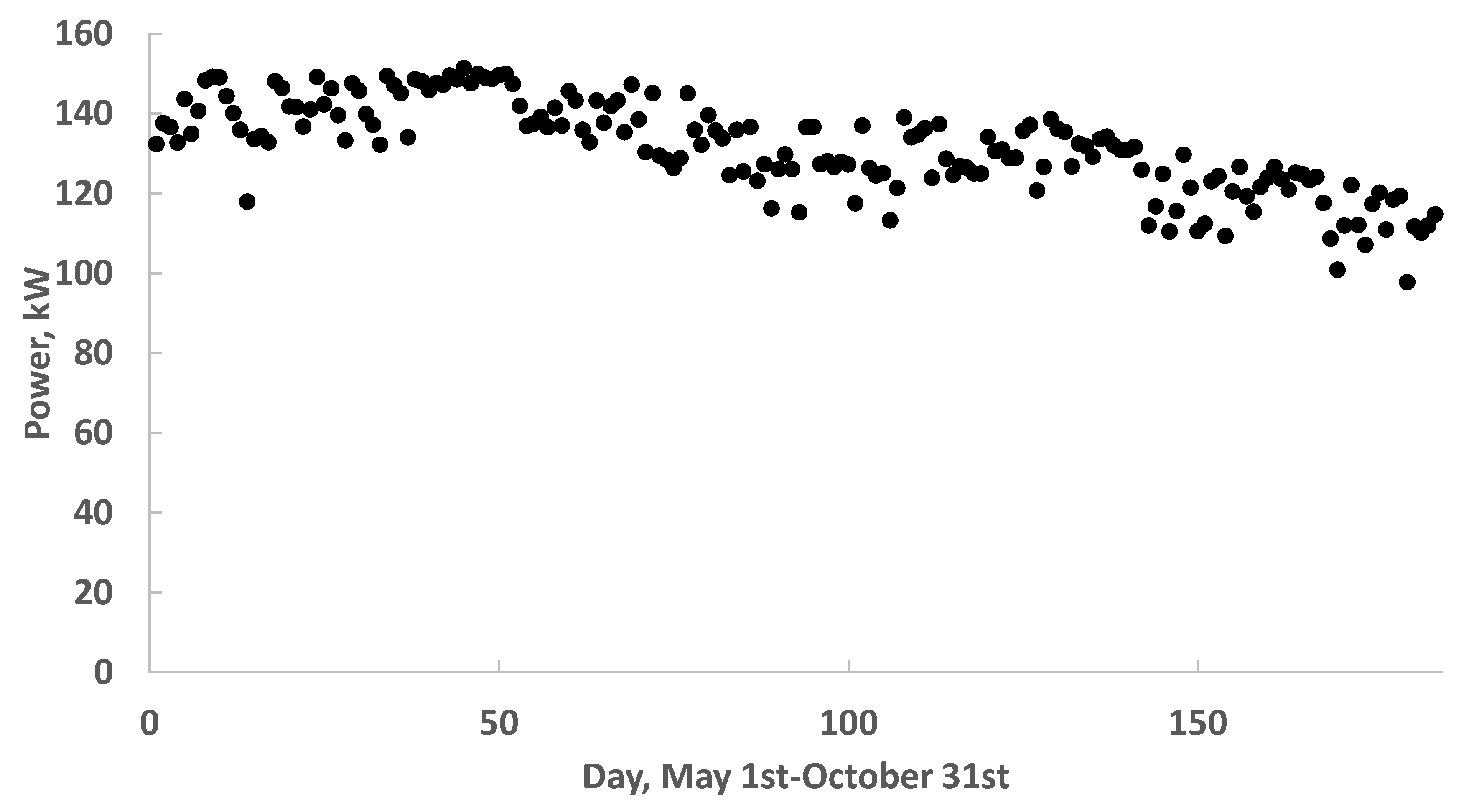
  • The power of the unit is significantly augmented at times of peak power demand, a very attractive feature for any renewable energy unit.
  • The addition of superheat in the supercritical cycle avoids the two-phase turbine expansion.
  • The thermal efficiency of the superheat cycle is significantly higher than the efficiencies of comparable solar thermal units and geothermal subcritical ORC units.
The following parts of this paper introduce the concept of the proposed geothermal-solar unit and its operation in the two modes. The governing equations of the operation are also presented with the pertinent P-h diagrams of the cycles. The results of the simulations for the operation of the power generation in the two modes are presented, including calculations on the area of solar collectors and the mass of salts for the thermal energy storage. The conclusions on the two modes of operation are succinctly presented in the final section.

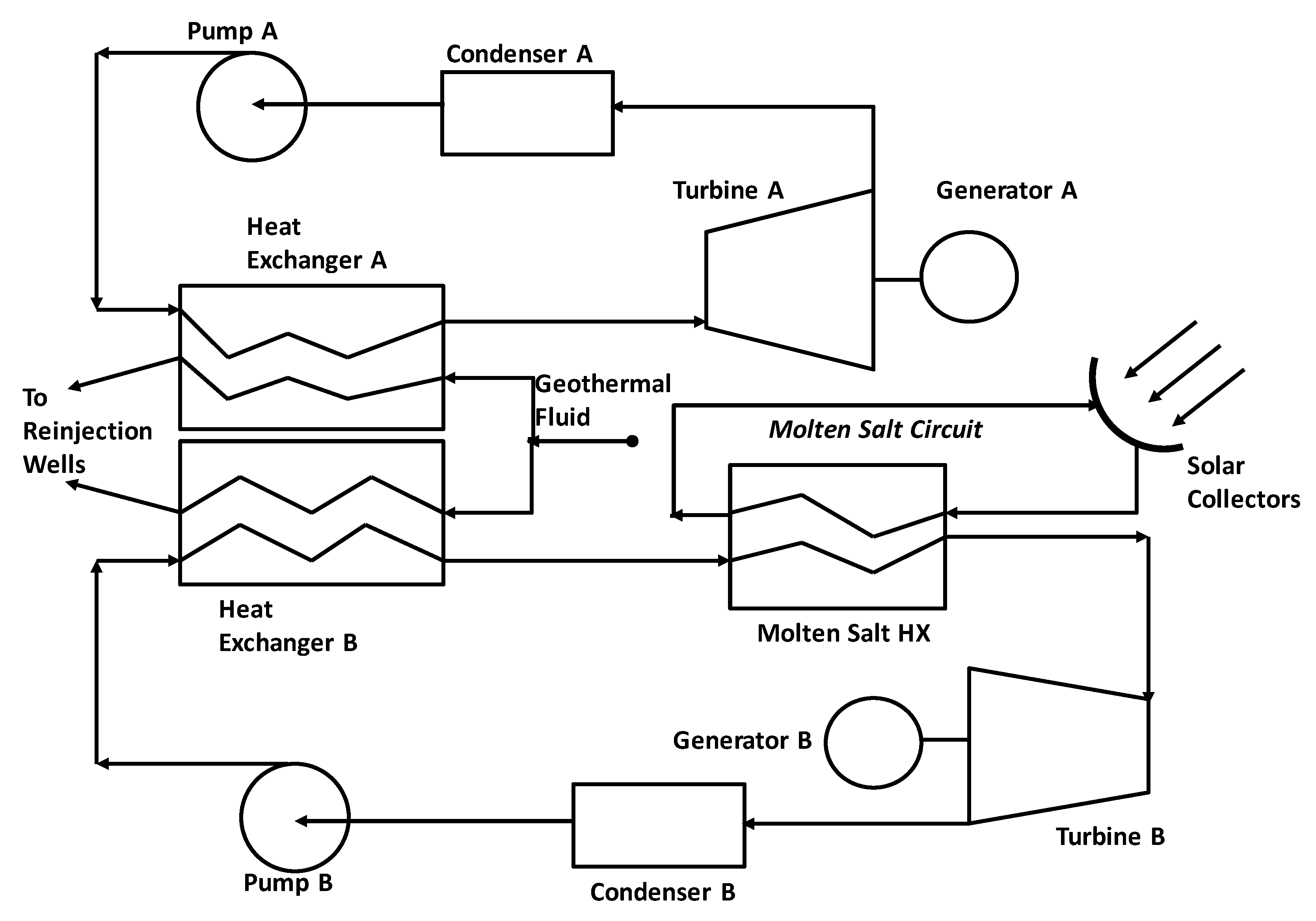
2. System Description and Operation

The proposed system operates in two modes:
A.
When there is no solar energy (nighttime) and when the electricity demand is not high (winter), the plant operates as an optimized geothermal binary plant, using butane as the working fluid, with subcritical butane vapor produced in a counter-current heat exchanger. While it is well-known that the working fluid of the ORC may be optimized [23], this type of optimization is not in the focus of this study. The working fluid selection through optimization is beyond a conceptual study and, for brevity we decided to only present results for butane, because its critical temperature is close to the type of geothermal energy resources (140–170 °C) that will be utilized in the next generation of power plants [4]. At these resource temperatures, butane is the most suitable working fluid to be used in a Rankine cycle [23]. It must be noted that geothermal resources at these lower temperatures exist in several countries and regions with geothermal potential including the USA, Mexico, the countries of Central America, East Africa, the Mediterranean Countries, Japan, Philippines, and P.R. China.
B.
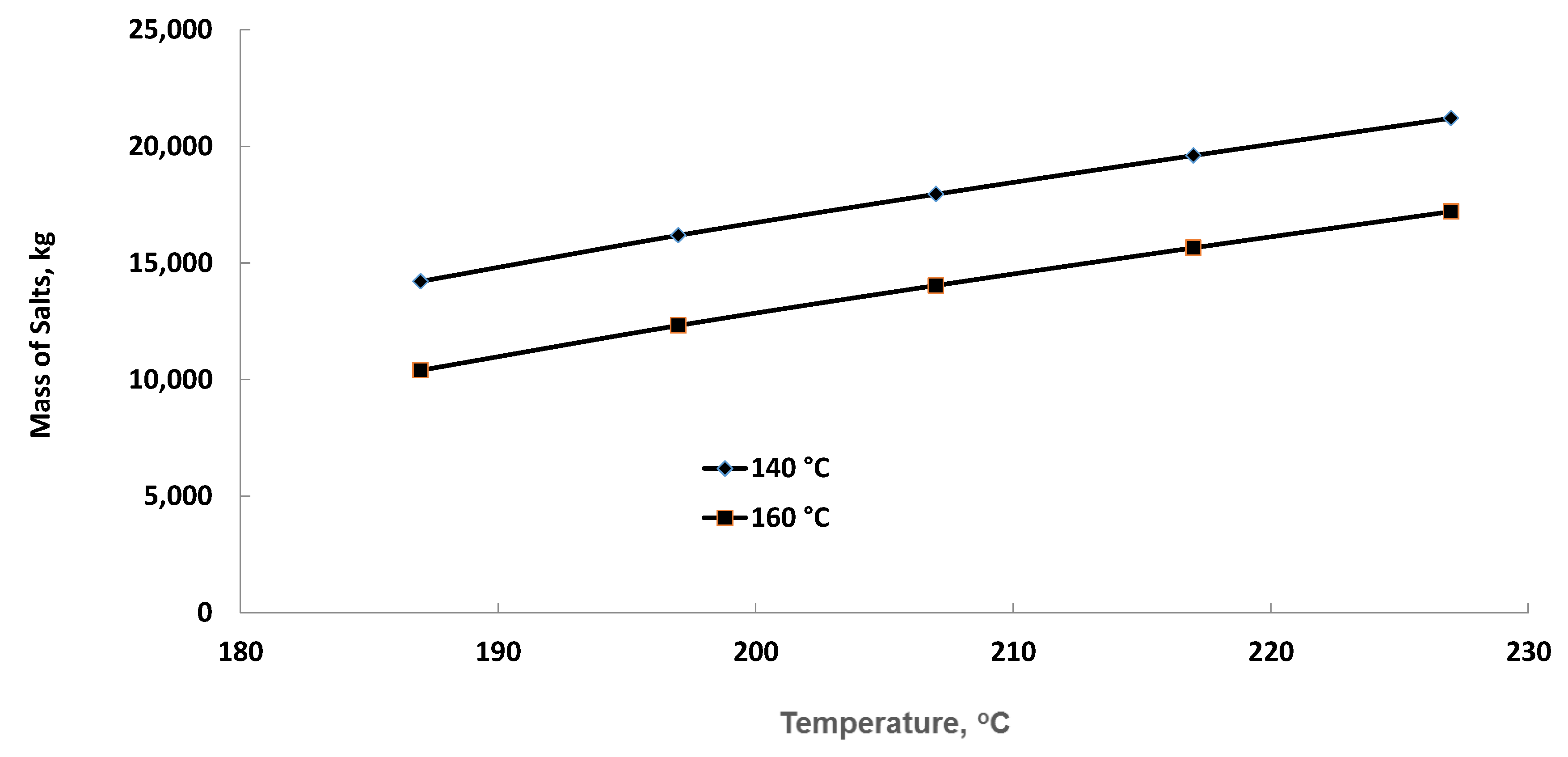
At the peak electricity demand hours, the unit operates at supercritical pressures. Heat is supplied to the working fluid, first by the geothermal fluid in a counter-current heat exchanger and secondly by irradiance. The latter is collected in parabolic collectors, similar to those suggested in [10], and stored as heat in a tank of molten salts. Heat storage enables the unit to operate steadily for several hours in the afternoon and early evening and to supply significantly higher electric power when the electricity demand is high.
Figure 2 shows the basic system design for the proposed geothermal-solar power plant. The upper diagram represents the cycle at the mode 1 of the unit’s operation. The pump receives the working fluid from the condenser and increases its pressure to a subcritical value. The fluid evaporates in the counter-current heat exchanger with the geothermal fluid supplying all the heat. The vapor expands in the turbine that drives a generator and produces power. The condenser is preferably cooled by a wet cooling system wherever sufficient cooling water is available. In the absence of cooling water, an air-cooling system must be used and this would reduce the power produced and the overall efficiency of the unit. The bottom diagram shows the second mode of operation with the bigger pump 2 raising the pressure of the working fluid to a supercritical pressure. Since relatively low-temperature geothermal fluids are not capable of increasing the temperature of the working fluid significantly higher than the critical temperature (for butane Tcr = 151.98 °C, Pcr = 3.796 MPa) solar irradiance provides the enthalpy to further increase the temperature of the working fluid up to 227 °C (500 K). At higher temperatures, the expansion process does not pass through the saturation region, where liquid droplets significantly reduce the isentropic efficiency of the turbine and, in addition, damage the turbine blades. Both turbines in the Figure mechanically drive generators that produce the electric power. It must be noted that Figure 2 is not a detailed blueprint of the proposed system, but only a schematic diagram that explains graphically the several processes in the two modes of operation. While it is feasible that the two modes of operation may share equipment, the calculations were performed for two independent cycles.
It is noted that the additional enthalpy enters the cycle through an energy storage system utilizing molten salts. This is necessary for the following reasons:
  • The power system may operate in mode 2 even after sundown during the early evening hours, when the electricity demand is still high.
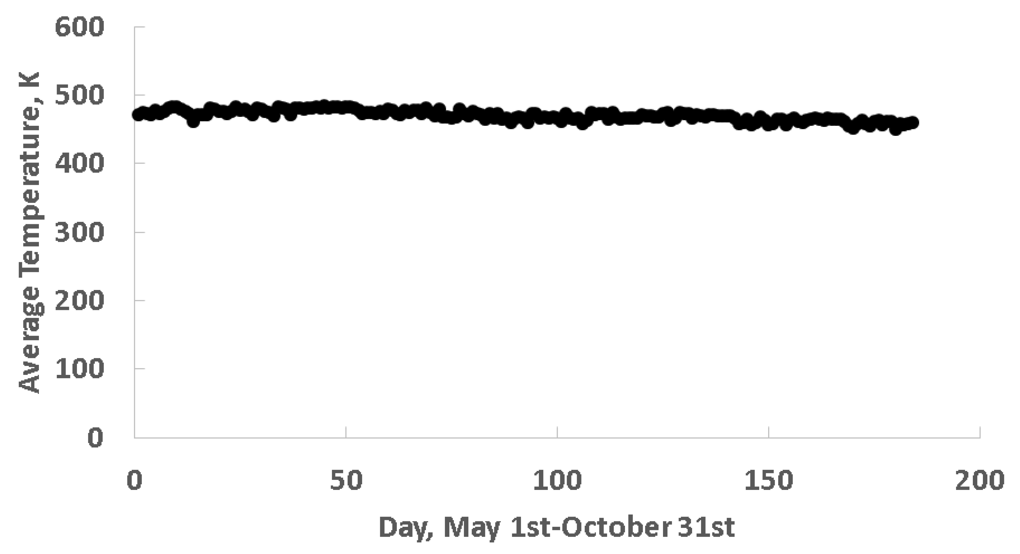
  • The energy storage system makes the ORC immune from diurnal fluctuations of irradiance resulting from the position of the sun and possible cloudiness. The geothermal fluid is supplied at steady-state for the entire duration of the plant’s operation.
The P,h diagrams (in scale) of the ORC cycles in mode 1 and mode 2 are shown in Figure 1a,b. The two modes of operation are also represented in the T,s diagrams (in scale) of Figure 3c,d. The processes in the two diagrams for mode 2 are labeled as follows:
1-2
Heating by the geothermal resource
2-3
Additional heating by solar irradiance.
3-4
Turbine expansion
4-5
Condensation
5-1
Pressurization
For the calculations the pressure of the supercritical cycle was chosen as 5 MPa, because this is sufficiently higher than the critical pressure of butane (Pcr = 3.796 MPa) to keep the cycle and the heat transfer away from the critical region, where instabilities occur. Four superheat temperatures of the working fluid are also indicated on the four state-points of the supercritical cycle. It is observed that, if the organic fluid were not superheated and its temperature remained at 150 °C, the expansion in the turbine would be mostly in the two-phase region and the dryness fraction at the exit of the turbine would be low. With appropriate superheat the entire expansion process is in the vapor region. This improves the efficiency and durability of the vapor turbine. The condenser temperature in both cases is 0.3269 MPa corresponding to a condenser temperature of 35 °C.
The choice of the highest temperature for the calculations (500 K) was primarily made for two reasons: First, the entire expansion of the working fluid (butane) is within the vapor region and outside the saturation curve, which ensures the correct operation of the turbine. Second, as will be seen in Figure 4, there is a maximum in the utilization efficiency of the solar heat that happens just before 500 K (at about 170 °C or 443 K) beyond this temperature, the effectiveness of adding more solar heat decreases.

3. Governing Equations

3.1. Mode 1, Non-Peak Hours

During mode 1 the cycle operates as an optimized subcritical ORC. The mass flow rate of the working fluid is obtained by the heat balance in the part of the heat exchanger where the working fluid evaporates. Since this fluid enters the heat exchanger as compressed liquid, the heat exchanger has a pinch point, where the minimum temperature difference between the two fluids, ΔT, occurs [2]. The mass flow rate of the working fluid is obtained from the heat balance in the evaporation section and is given by the expression:
m ˙ w f = m ˙ g f [ h g f ( T g i ) h g f ( T s a t + Δ T ) ] h w f ( T e ) h w f ( T s a t ) ,
where m ˙ w f is the mass-flow rate of the working fluid; m ˙ g f is the mass-flow rate of the geothermal brine; h denotes the enthalpy property for both fluids with the subscripts gf and wf denoting geothermal fluid and working fluid respectively; Tgi is the temperature of the geothermal entering the heat exchanger; Tsat is the saturation temperature of the working fluid at the given pressure; ΔT is the temperature difference between brine and working fluid at the pinch point of the heat exchanger. The parentheses in Equation (1) denote arguments of the enthalpy function.
The produced vapor is fed to the turbine. The maximum specific work that may be obtained from this resource is equal to the exergy of the vapor:
w m a x = e 1 e 0 = h 1 h 0 T 0 ( s 1 s 0 ) ,
where h denotes the enthalpy; s the entropy; the subscripts 1 denotes the state of the produced vapor at the exit of the heat exchanger; and the subscript 0 denotes the state of the working fluid at the environmental pressure and temperature.
In the case of organic fluids that exhibit retrograde condensation, the working fluid exits the turbine a temperature different than the environmental temperature and the maximum specific work is not achieved. The power produced by the organic fluid turbine is:
W ˙ =   m ˙ w f w S η T ,
where ws is the isentropic work and η T is the efficiency of the turbine.
The net power produced in the cycle includes the specific work of the turbine and the pump:
W ˙ n e t = m ˙ w f ( w S η T w P / η P ) ,
where w P is the isentropic pump work; and η P is the pump efficiency.

3.2. Mode 2, Peak Hours

In this mode of operation, the working fluid from the condenser is pressurized to a supercritical pressure. The working fluid enters the heat exchanger as pressurized liquid—at pressure PH—and exits as supercritical fluid. The mass flow rate of the working fluid is, again, obtained from the energy balance in the entire heat exchanger:
m ˙ w f = m ˙ g f [ h g f ( T g i ) h g f ( T g e ) ] h w f ( T w i ) h w f ( T w e ) ,
where h denotes the enthalpy function; Ti and Te indicate the inlet and outlet temperatures, respectively, of the geothermal fluid (subscript g) and of the working fluid (subscript w).
At this mode of operation, the temperature of the working fluid is increased in the range 460–500 K (187–227 °C) using the energy produced by solar irradiance and stored in a tank of molten salts. The addition of heat at the higher temperatures always improves the first-law and exergetic efficiencies of cycles and provides more power. Heat storage systems are currently in operation with solar-thermal power plants including the Gemasol (formerly Solar Tres) power plant in Andalucía, Spain [1]. The rate of heat needed to raise the temperature of the working fluid from Twe to the temperature TwH, the highest temperature in the cycle, is:
Q s ˙ = m ˙ w f [ h w H ( P H , T w H ) h w e ( P H , T w e ) ] ,
where the variables in the parentheses indicate the arguments of the enthalpy function—the pressure and temperature at which the enthalpy is calculated. An implicit assumption in this equation is that the working fluid pressure drop in the two heat exchangers is negligible. Since the power plant operates at this mode for a limited time daily, t, the total heat removed from the molten salts tank is: Q = t Q s ˙ . This quantity of heat is supplied by the solar irradiance, through an array of solar collectors, to the molten salts during an entire day. If the collector efficiency is ηC, and the storage system (through heat lost) transfers a fraction, ηst, of its heat to the environment, then the total incident solar energy to the collectors is:
A η C 0 d a y ( S ˙ d t ) = t Q s ˙ 1 η s t A = t Q s ˙ ( 1 η s t ) η C 0 d a y ( S ˙ d t ) ,
where S ˙ is the insolation (usually given in W/m2) and is variable on a given day; A is the total area of the parabolic collectors and the integral is taken over all the daylight hours. When the insolation is known from local solar data, this equation may be used for the calculation of the area of the parabolic collectors. In the calculations that follow, we determined the area of the collectors based on the average insolation of ten days in July (8 July to 17 July) when the demand for power typically reaches a maximum. In order to avoid weather fluctuations and the variability of the insolation, S ˙ , the five-year average of the data for those ten days were used. This multi-year data is available by the National Renewable Energy Laboratory (NREL) [24]. The location of the irradiance data we used was the city of Yuma, Arizona, where the insolation values are similar to those in Mexico and Central America. Based on the calculated area, the temperature, TwH, of the working fluid was determined for every day, when the system operates in mode 2, using Equation (6).
As with mode 1, the net power obtained from the cycle in mode 2 is given by Equation (4). It must be noted that, in mode 2 the temperature and pressure of the working fluid are much higher than those in mode 1.

4. Results and Discussion

Table 1 gives a summary of the conditions of operation of the geothermal-solar power plant in the two modes of operation. The values of the parameters and equipment efficiencies are typical of values met in actual geothermal and solar installations.
The thermodynamic properties of geothermal brine were taken to be those of water at the temperature and pressure of the brine [25]. The properties of butane were obtained from the software package REFPROP [26]. The value of the solar collector efficiency was obtained from [27]. The conditions used in this Table are on the conservative side (e.g., special turbines may be designed with ηT be closer to 88%; ηP may be up to 82%; the pinch point (ΔT) and minimum temperature differences may be as low as 3 °C) reflecting the fact that the operation of the power plant may not be as well optimized other power units. The condenser temperature value (35 °C) implicitly assumes that water is available to be used as coolant.

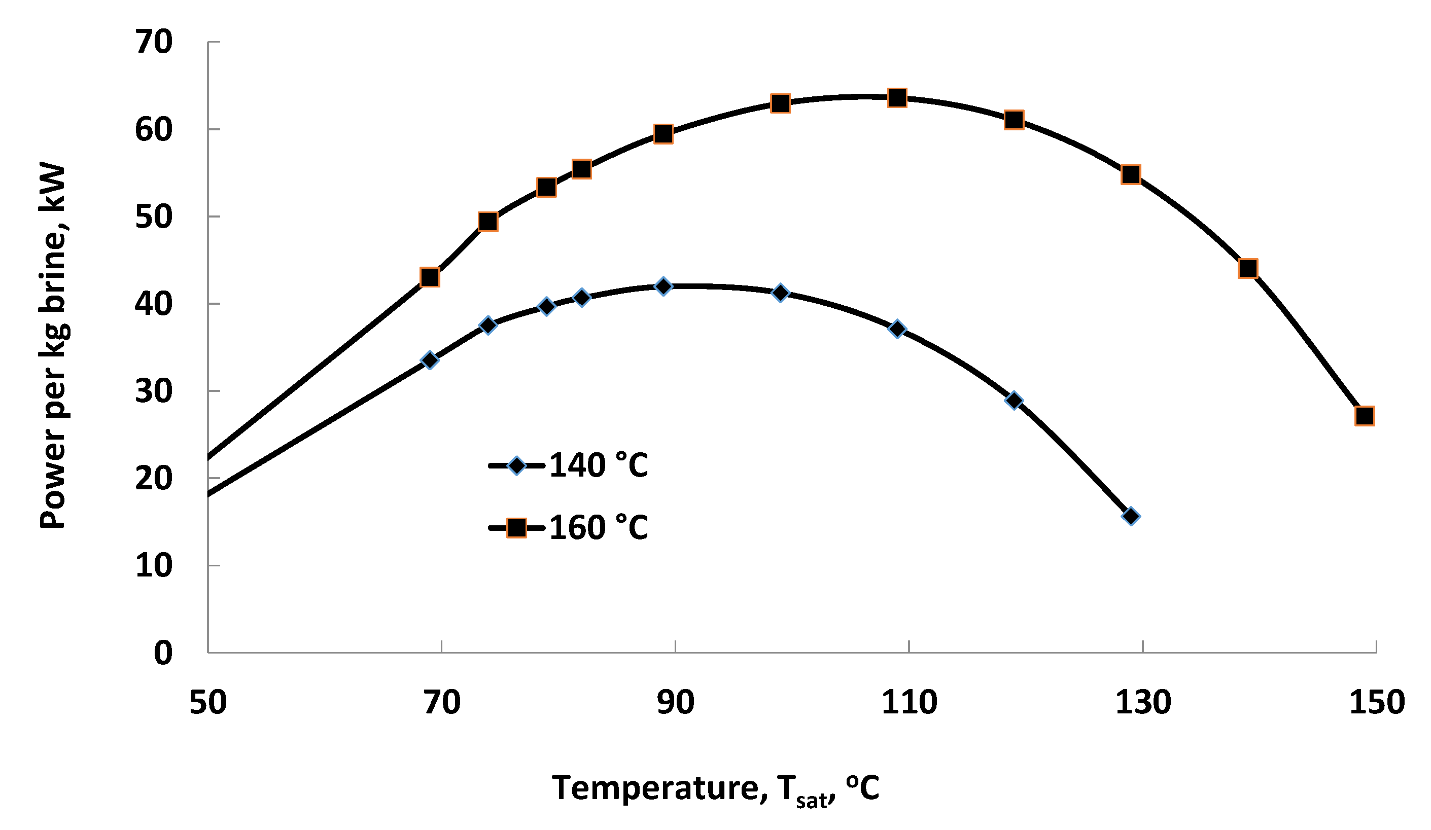
4.1. Operation in Mode 1

When operating at the non-peak hours, the unit operates as a subcritical binary geothermal power plant [1,2]. Once an optimum working fluid is determined, the conditions of the cycle may be optimized by the choice of an optimum saturation pressure and temperature where the evaporation of the working fluid occurs. Table 2 shows the conditions at the optimum, Tsat and Psat; the flow rate of butane for 1 kg/s of geothermal brine input; power produced for 1 kg/s of geothermal brine; and the exergetic efficiency of the unit for two values of the resource temperature 140 °C, and 160 °C (413K, and 433 K respectively).
For the calculation of the exergetic efficiencies, the dead state of the substances is 100 kPa and 35 °C (308 K).
It must be noted that the lower range of the resource temperatures corresponds to the approximate temperature of the effluents of a few single-flash geothermal power plants, as for example the Miravalles power plant in Costa Rica (units 1, 2 and 3) that re-injects brine in the range 156-159 °C. In such cases the resource is available and no additional geothermal wells need to be drilled. In that power plant, there is an ORC unit (the 19 MW Unit 5) that utilizes the thermal energy of the wasted brine of the flashing units [2].
Figure 5, which depicts the net power W ˙ n e t vs. the evaporation temperature, shows graphically the results of the optimization for Tgi = 160 °C and 140 °C. As with all the binary geothermal cycles, it is also observed in this Figure that, at the maximum power the curve is flat [1]. This implies that any uncertainty in the optimum value of Tsat has very small effect on the power produced at the optimum.

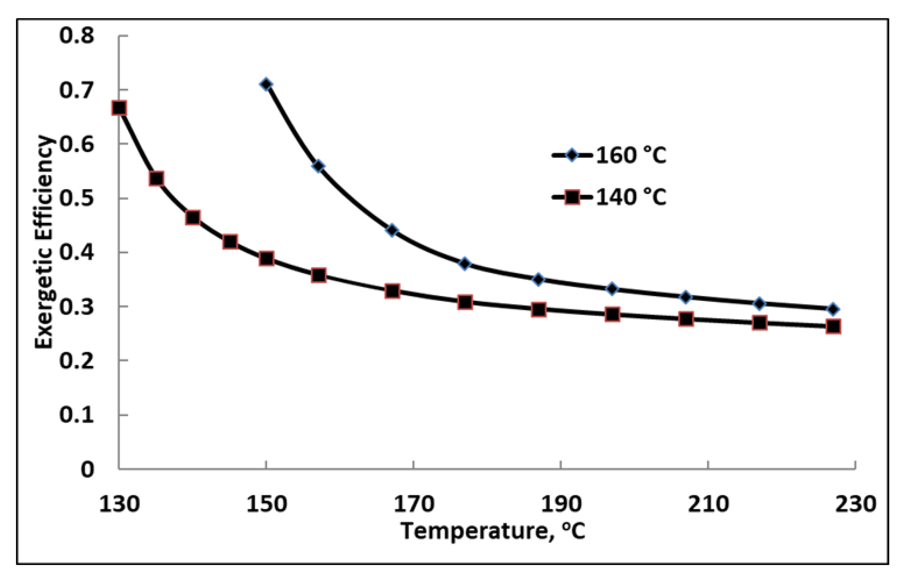
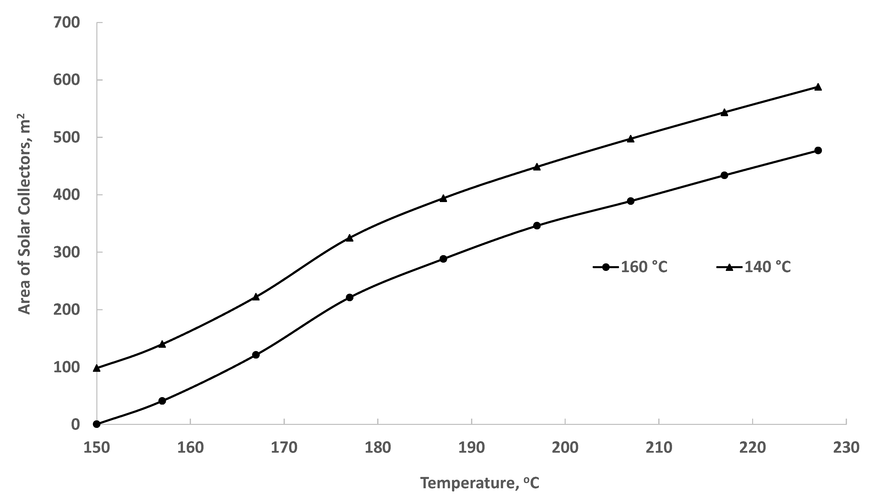
4.2. Operation in Mode 2

When the system operates in mode 2, the working fluid is at supercritical pressure and exits the heat exchanger as a supercritical fluid. Even though it exits the heat exchanger at a higher temperature, the supercritical fluid has lower enthalpy than the subcritical vapor of mode 1. This implies that the mass flow rate of the working fluid is higher in mode 2 than in mode 1. The enthalpy of the supercritical fluid increases significantly when it absorbs heat from the mixture of molten salts where the solar energy is stored. The combination of higher mass flow rate and increased enthalpy results in significantly higher power generated by the working fluid. Figure 6 shows the power generated by the unit when it operates in mode 2; receives geothermal brine at Tgi = 160 °C (433 K); and the temperature of the working fluid (butane) is increased in the range from 150 °C to 227 °C (423 K to 500 K). The Figure also shows the necessary rate of heat supplied from the molten salts (essentially the “solar” heat). Because this quantity of heat is stored in the molten salts tank, a 10% loss for the storage tank during the period of storage was stipulated for the calculations. It must be noted that the trends for Tgi = 140 °C (413 K) are very similar. We decided not to include the latter in order to avoid clutter in the Figure.
A comparison of Figure 5 and Figure 6 shows that almost as much as three times more power may be produced when the cycle is supercritical and solar irradiance supplements the geothermal heat for the production of power. The figures also show that the solar heat supplement is significant. One of the reasons for the significant increase in power is that—because there is not boiling of the working fluid—all the enthalpy of the geothermal fluid is spent in raising the temperature of the working fluid in the brine-to-working fluid heat exchanger. With the stipulated 10 °C difference in that heat exchanger, and following Equations (1) and (5), the mass flow rate of the working fluid (butane) in mode 2 is 1.45 kg/s for every 1 kg/s of the geothermal fluid, compared to 0.80 kg/s in mode 1.
Table 3 shows the mass flow rate of the secondary fluid, the total power produced (with 85% turbine efficiency), the rate of heat supplied by the solar part of the cycle, and the rate of heat supplied by the geothermal fluid, Q ˙ g e o , when the inlet geothermal brine temperature is Tgi = 140 °C, and 160 °C.
The effectiveness of the additional heating from solar energy is also of interest. Table 4 provides information on the incremental effectiveness of using solar thermal energy for the production of power. The Table shows the additional power obtained from the system when it operates in mode 2; the additional rate of heat required for the superheating; and the effectiveness of solar heating, defined as the ratio of the incremental power to the incremental rate of heat.
The effectiveness of solar heating is shown in Figure 6 as a function of the high temperature for the two temperatures of the geothermal resource. It is observed that the effectiveness exhibits a weak maximum, at approximately 25%, when the temperature of the working fluid is increased by about 20 °C. After this maximum the effectiveness drops at a slow rate. The maximum occurs when the vapor at the exit of the turbine is close to the saturation line of butane. Beyond this point, the turbine exhausts superheated vapor with finite exergy and the isentropic turbine work is limited. The existence of the maximum indicates that a moderate amount of superheating by solar energy may be more useful in such cycles. The corresponding effectiveness for the solar heat quoted in [21] was 24.3% (even though the solar heat was added at 160 °C in that study) because the authors did not use the upper temperature of the cycle as a parameter.
The following observations are made from the comparison of the unit’s operation in the two modes of operation:
  • The power produced per unit mass flow rate of the brine may be significantly increased by the addition of solar heat.
  • The rates of heat supplied by the solar irradiance and the geothermal fluid, Q ˙ s f and Q ˙ s g e o , are of the same order of magnitude, almost equal in a few cases.
  • The significantly higher power produced by the cycle would be very welcome by the electric power grid, when it is produced during the peak hours of late afternoon and early evening.
One may define the exergetic efficiency of the unit in mode 2 as the ratio of the produced power divided by the sum of the rates of exergy entering the power as geothermal resource and solar exergy. Because of the high temperature of the emitting source (the sun) the exergy of the solar irradiance is 96% of the corresponding thermal energy [28]:
η e x = W ˙ m ˙ g f e g f + 0.96 Q ˙ s o l ,
where egf is the specific exergy of the geothermal resource. Figure 7 depicts the results of the exergetic efficiency of the power plant in mode 2 when the organic fluid is superheated in the range 150–227 °C (423–500 K). The rather paradoxical result of the decreasing exergetic efficiency with the superheat temperature of the working fluid is a consequence of the high exergy of solar irradiance, Esol = 0.96Qsol. As more and more high-exergy solar heat is added to the cycle, the corresponding ratio of Equation (8) decreases. However—and unlike the use of fossil fuels to superheat the working fluid—this solar heat input does not correspond to primary energy resources destruction because: (a) solar energy is renewable (it will be available in the future); and (b) the exergy of the solar irradiance would have been anyway locally dissipated, as low temperature heat. One must notice, however, that, because the heat is added at a higher temperature, the thermal (first law) efficiency of the cycle increases significantly from 11.8% with zero superheat to 16.6% at 227 °C superheat. This is higher than the efficiency (13.4%) of the solar thermal power plant with heat storage in [17] and significantly higher than the 8–12% efficiency of flashing and binary (ORC) units that utilize geothermal fluid at comparable temperatures [2,4].
The solar rate of energy supplied to the power plant is captured by solar collectors. Based on the solar irradiance in Yuma, AZ, obtained from NREL [24] we calculated the solar collector area that must be erected for the operation of the plant in mode 2. The collector efficiency is 75% [27], with the additional 10% loss of heat in the storage system during the operation of energy storage (ηst = 90%), the area of the collectors is calculated using Equation (7). Figure 8 shows these results for the two temperatures of geothermal fluid inputs.
The mass of the molten salts needed to supply the heat to the cycle for the time period t is obtained by the equation
m s a l = Q ˙ s o l t c Δ T s a l ,
where c is the specific heat of the salts and Δ T s a l is the allowed temperature difference for the molten salts during the heat transfer to the cycle. For the Solar Salt, which is preferentially used with solar installations c = 1.482 kJ/kgK [29]. Figure 9 shows the needed mass of the salts (per 1 kg/s of the geothermal fluid) as a function of the upper temperature of the cycle and for an allowable salt temperature difference Δ T s a l = 100 K. The properties of the Solar Salt from [29] were used for the calculations depicted in this Figure. The sizing of the heat exchanger and the design of the coils within the tank is not in the purview of this study.
Because solar irradiance is variable and the geothermal-solar unit would operate with a fixed solar collector area, calculations were also performed to determine the expected average daily fluctuations of the working fluid temperature as it enters the turbine, and of the power produced during the six hours of operation in mode 2. In order to avoid the irradiance variability due to the weather, the five-year average hourly insolation was used in the calculations. For the solar collector area of 350 m2 per kg/s of geothermal fluid at 160 °C—the area required to increase the working fluid temperature to become approximately 470 K (197 °C). Based on the daily amount of insolation, Figure 10 shows the daily temperature the working fluid attains during the period of high air-conditioning demand in the area, from 1 May to 31 October. It is observed in the figure that, despite the solar energy variability, the average daily temperatures are in the range 451 K to 484 K (178–211 °C) during the entire season. As shown in the P,h diagram of Figure 3b, at the higher cycle pressure of 5 MPa and with this range of higher temperatures, the working fluid expansion in the turbine is always on the vapor side of the saturation curve, significant amount of liquid is not produced during the expansion process and the turbine(s) used in the cycle would operate properly. It is also observed in the figure that the working fluid temperature gradually decreases in September and October (days 124 to 184) because autumn sets in, the daylight hours are less, and the total daily heat absorbed by the molten salts decreases.
Using the average daily insolation in the area and the total amount of heat absorbed by the molten salts, we calculated the power produced by the cycle in mode 2 during the period 1 May to 31 October. Figure 11 shows the power produced by the combined geothermal-solar cycle for 1 kg/s of the geothermal resource, when the supercritical working fluid temperature is raised to the temperatures of Figure 10. For the geothermal fluid at 160 °C this happens when the area of the solar collector is constant, at 350 m2. It is observed in this figure that the power produced remains in the range 151–100 kW. If higher power generation uniformity is required, seasonal energy storage in the molten salts should be attempted with equal amounts of heat dispensed to the cycle from day to day. This may require additional collector area.
It must be noted that the calculations and results in Figure 4 through Figure 11 pertain to 1 kg/s of the geothermal resource brine. Geothermal wells produce significantly higher mass flow rates, typically in the range 60–80 kg/s, and an actual geothermal power plant utilizes the brine produced by a group of wells. An actual geothermal-solar power plant would utilize more solar energy and produce significantly more power at a commensurate cost.
Based on the results obtained for 1 kg/s geothermal brine supply, we performed calculations for the power to be delivered by a geothermal well producing 80 kg/s of brine at 160 °C (433 K). When operating in mode 1 with an optimized subcritical cycle and with an 85% efficient turbine, the unit would produce 5.1 MW of power with butane as a working fluid. When the power plant operates in mode 2 for six hours during the day and the temperature of the working fluid is raised to 500 K, the power plant would produce 13.8 MW, a significant increase in power during the peak demand hours. The total rate of heat supplied to the supercritical cycle, is 75.2 MW of which 33.8 MW is derived from the solar collectors and 41.4 MW from the geothermal fluid. Based on the average insolation in the Imperial Valley area, 75% solar collector efficiency and 10% heat losses in the molten salts storage tanks, the solar part of the rate of heat would be supplied by approximately 38,200 m2 of parabolic collectors’ area. The power plant would also utilize approximately 1400 tons of molten salts (Solar Salt) in tanks of approximately 900 m3 total volume. All in all, the power plant would produce annually 54,228 MWh of electric energy, of which 15,152 MWh would be generated during peak power demand hours.
It must be noted that, if the geothermal source of heat were not available and the entire rate of heat were supplied by solar collectors or reflectors, then the area of the solar collectors would be approximately 65,900 m2 and the volume of the molten salts to approximately 1600 m3. It becomes apparent that the utilization of the low-temperature geothermal heat significantly cuts into the total sizes of the collectors and storage tanks, which represent a major part of the capital expenses of thermal solar power plants. Such considerations lead to the deduction that when solar thermal power plants are to be constructed, engineers should investigate the availability of low-temperature geothermal heat sources, which would supply a fraction of the needed rate of heat and would cut down on the capital costs for solar collectors and storage tanks. Another consideration that would improve the economics of such power plants is the sharing of heat exchange equipment—the main heat exchanger and the condenser. In this case, the equipment will not be optimized for use in one of the two modes and additional consideration must be given to the off-design operation.

5. Conclusions

A geothermal-solar power plant that operates with low-temperature geothermal brine is capable to supply two to nine times more power than an optimized subcritical ORC unit. An additional advantage of the geothermal-solar unit is that it is capable to supply constant (non-variable) power during the hours of its operation. A supercritical ORC may be used in hybrid units with solar energy supplying the rate of heat needed for superheating the working fluid. The generated additional power may be used at peak demand hours to alleviate the higher electricity demand caused by air-conditioning. The combination of the supercritical cycle and superheat from solar irradiance results in significantly higher thermal efficiencies (16.6%) in comparison to other types of geothermal power plants, even though the exergetic efficiency is lower because of the addition of high-exergy irradiance. Since solar irradiance is a diffuse source of heat, significant collector area and heat storage are needed for the capture and utilization of the solar part of heat addition. This type of renewable energy power plant will be very attractive in locations where thermal-solar power plants are to be built and low-temperature geothermal resources exist nearby.

Author Contributions

B.B. Contributed with the most of the calculations in this paper. E.E.M. contributed with the conceptualization, analysis and writing. D.N.M. contributed with the conceptualization, analysis, and methodology. All authors have read and agreed to the published version of the manuscript.

Funding

This research was partly supported by the Tex Moncrief Chair at TCU.

Acknowledgments

This research was partly supported by the Tex Moncrief Chair of Engineering at TCU.

Conflicts of Interest

The authors declare no conflict of interest.

Nomenclature

List of Symbols
cspecific heat capacity
henthalpy
eexergy
mmass
Ppressure
Qheat
sentropy
Sirradiance
ttime
Ttemperature
wspecific work
ηefficiency
Subscripts
0pertains to the environment
Ccollector
eexit/outlet
gfgeothermal fluid
Hhighest
iinlet
maxmaximum
Ppump
sisentropic
satsaturated
solsolar
salsalts
ststorage
Tturbine
wfworking fluid
Superscript
. (dot)denotes time rate
Abbreviations
GCCGlobal Climate Change
ORCOrganic Rankine Cycle
PVPhotovoltaic

References

  1. Michaelides, E.E. Energy, the Environment, and Sustainability; CRC Press: Boca Raton, FL, USA, 2018. [Google Scholar]
  2. Di Pippo, R. Geothermal Power Plants—Principles, Applications, Case Studies and Environmental Impact, 3rd ed.; Elsevier: Oxford, UK, 2012. [Google Scholar]
  3. Bertani, R. Geothermal Power Generation in the World 2005–2010 Update Report. Geothermics 2012, 41, 1–29. [Google Scholar] [CrossRef]
  4. Michaelides, E.E. Future Directions and Cycles for Electricity Production from Geothermal Resources. Energy Convers. Manag. 2016, 107, 3–9. [Google Scholar] [CrossRef]
  5. Manfrida, G.; Tempesti, D.; Fiaschi, D.; Bruscoli, L. Improving the Environmental Sustainability of Flash Geothermal Power Plants—A Case Study. Sustainability 2015, 7, 15262–15283. [Google Scholar]
  6. Freeman, E.; Occello, D.; Barnes, F. Energy Storage for Electrical Systems in the USA. AIMS Energy 2016, 4, 856–875. [Google Scholar] [CrossRef]
  7. Weber, M.E. Making Renewables Work. Mech. Eng. 2016, 138, 12–17. [Google Scholar]
  8. DeValeria, M.K.; Michaelides, E.E.; Michaelides, D.N. Energy and thermal storage in clusters of grid-independent buildings. Energy 2019, 190, 116440. [Google Scholar] [CrossRef]
  9. Michaelides, E.E. Making Texas Green. Mech. Eng. 2019, 141, 32–37. [Google Scholar] [CrossRef] [Green Version]
  10. Bronicki, L.Y. Hybrid Geothermal Power Plant. US Patent and Trademark Office; U.S. Patent #9,331,547, 3 May 2016. [Google Scholar]
  11. Kestin, J. (Ed.) A Sourcebook for the Production of Geothermal Electric Power; DOE: Washington, DC, USA, 1980. [Google Scholar]
  12. Lentz, A.; Almanza, R. Solar-geothermal hybrid system. Appl. Therm. Eng. 2006, 26, 1537–1544. [Google Scholar] [CrossRef]
  13. Greenhut, A.D.; Tester, J.W.; DiPippo, R.; Field, R.; Love, C.; Nichols, K.; Augustine, C.; Batini, F.; Price, W.; Gigliucci, G.; et al. Solar-Geothermal Hybrid Cycle Analysis for Low Enthalpy Solar and Geothermal Resources. In Proceedings of the World Geothermal Congress 2010, Bali, Indonesia, 25–29 April 2010. [Google Scholar]
  14. Zhou, C.; Doroodchi, E.; Moghtaderi, B. An in-depth assessment of hybrid solar-geothermal power generation. Energy Convers. Manag. 2013, 74, 88–101. [Google Scholar] [CrossRef]
  15. Yang, J.; Li, J.; Yang, Z.; Duan, Y. Thermodynamic analysis and optimization of a solar organic Rankine cycle operating with stable output. Energy Convers. Manag. 2019, 187, 459–471. [Google Scholar] [CrossRef]
  16. Kutlu, C.; Li, J.; Su, Y.; Pei, G.; Riffat, S. Off-design performance modeling of a solar organic Rankine cycle integrated with pressurized hot water storage unit for community level application. Energy Convers. Manag. 2018, 166, 132–145. [Google Scholar] [CrossRef] [Green Version]
  17. Manfrida, G.; Secchia, R.; Stańczyk, K. Modelling and simulation of phase change material latent heat storages applied to a solar-powered Organic Rankine Cycle. Appl. Energy 2016, 179, 378–388. [Google Scholar] [CrossRef] [Green Version]
  18. Ayub, M.; Mitsos, A.; Hadi, G. Thermo-economic analysis of a hybrid solar-binary geothermal power plant. Energy 2015, 87, 326–335. [Google Scholar] [CrossRef]
  19. Wang, Q.; Huang, Q. Research on integrated solar and geothermal energy engineering design in hot summer and cold winter area. Procedia Eng. 2011, 21, 648–655. [Google Scholar] [CrossRef] [Green Version]
  20. Al-Ali, M.; Dincer, I. Energetic and exergetic studies of a multigenerational solar-geothermal system. Appl. Therm. Eng. 2014, 71, 16–23. [Google Scholar] [CrossRef]
  21. McTigue, D.; Castro, J.; Mungas, J.; Kramer, N.; King, J.; Turchi, G.; Zhua, G. Hybridizing a geothermal power plant with concentrating solar power and thermal storage to increase power generation and dispatchability. Appl. Energy 2018, 228, 1837–1852. [Google Scholar] [CrossRef]
  22. Stillwater Facility, Annual, 2019, Electricity Data Browser, Energy Information Administration. Available online: https://www.eia.gov/electricity/data/ (accessed on 20 September 2019).
  23. Edrisi, B.; Michaelides, E.E. Effect of the working fluid on the optimum work of binary-flashing geothermal power plants. Energy 2013, 38, 389–394. [Google Scholar] [CrossRef]
  24. Wilcox, S. National Solar Radiation Database 1991–2010 Update: User’s Manual; Technical Report NREL/TP-5500-54824; National Renewable Energy Laboratory: Golden, CO, USA, 2012. [Google Scholar]
  25. Michaelides, E.E. Thermodynamic Properties of Geothermal Fluids. Trans. Geoth. Resour. Counc. 1981, 5, 361–364. [Google Scholar]
  26. REFPROP. Reference Thermodynamic and Fluid Transport Properties; National Institute of Standards and Technology: Boulder, CO, USA, 2013. [Google Scholar]
  27. Kutscher, C.; Burkholder, F.; Stynes, K. Generation of a Parabolic Trough Collector Efficiency Curve from Separate Measurements of Outdoor Optical Efficiency and Indoor Receiver Heat Loss; NREL/CP-5500-49304; National Renewable Energy Laboratory: Golden, CO, USA, 2010. [Google Scholar]
  28. Bejan, A. Unification of Three Different Theories concerning the Ideal Conversion of Enclosed Radiation. J. Solar Energy Eng. 1987, 109, 46–51. [Google Scholar] [CrossRef]
  29. Serrano-López, R.; Fradera, J.; Cuesta-López, S. Molten salts database for energy applications. Chem. Eng. Process. Process Intensif. 2013, 73, 87–102. [Google Scholar] [CrossRef] [Green Version]
Figure 1. The development of the duck curve in the supply of electric power, when solar energy supplies a fraction of the total annual energy consumed. Data from [8].
Energies 13 01018 g001
Figure 2. The two modes of operation of the geothermal-solar hybrid system.
Energies 13 01018 g002
Figure 3. (a) Subcritical ORC cycle, at the optimum pressure for the 160 °C resource, 1.73 MPa. (b) Supercritical ORC cycle with high pressure 5 MPa. The upper temperature of the cycle is 500 K (227 °C). (c) Subcritical ORC cycle, at the optimum pressure for the 160 °C resource, 1.73 MPa. (d) Supercritical ORC cycle with high pressure 5 MPa. The upper temperature of the cycle is 500 K (227 °C).
Energies 13 01018 g003aEnergies 13 01018 g003b
Figure 4. The effectiveness of incremental heat rate addition exhibits a weak maximum.
Energies 13 01018 g004
Figure 5. Power optimum for Tgi 140 and 160 °C.
Energies 13 01018 g005
Figure 6. Power produced and rate of heat from solar irradiance at Mode 2 with Tgi = 160 °C (423 K).
Energies 13 01018 g006
Figure 7. Exergetic efficiency of the power plant in mode 2. The high exergy input of the solar irradiance has an adverse effect on ηex.
Energies 13 01018 g007
Figure 8. Solar Collector area in mode 2 operation per kg/s of brine mass flow rate.
Energies 13 01018 g008
Figure 9. Mass of salts needed per 1 kg/s of the resource fluid ( Δ T s a l = 100 K).
Energies 13 01018 g009
Figure 10. Daily temperature of the operation of the ORC in mode 2.
Energies 13 01018 g010
Figure 11. Daily power generated by the ORC in mode 2.
Energies 13 01018 g011
Table 1. Conditions of the geothermal-solar power plant.
Working FluidButane
Temperature of geothermal brine140–160 °C (liquid because of high pressure)
Condenser Temperature, T035 °C
Turbine efficiency, ηT85%
Pump efficiency, ηP82%
Pinch point temperature difference (mode 1), ΔT10 °C
Minimum temperature difference (mode 2)10 °C
Fraction of heat lost in molten salts tank, ηst,10%
Solar collector efficiency, ηC75%
Daily hours of operation in mode 26 h (21,600 s)
Table 2. Optimum operating conditions of the ORC in mode 1 (subcritical cycle) for two geothermal resource temperatures. The mass flow rate and power are per kg/s of the geothermal fluid.
Tgi, °C, (K)140 (413)160 (433)
Tsat, K362382
Psat, MPa1.171.74
m ˙ s f , kg/s0.700.8038
W ˙ n e t , kW42.063.6
ηex67%74%
Table 3. Operational parameters of the geothermal solar power plant at Mode 2 with two high temperatures, 460 K and 500 K.
Tgi, K, (°C)433, (160)413, (140)
m ˙ s f , kg/s1.45421.4945
W ˙ n e t , kW with TsH = 460 K135.5139.7
Q ˙ s f , kW312.8427.6
Q ˙ g e o , kW481.2418.4
W ˙ n e t , kW TsH = 500 K172.6177.7
Q ˙ s f , kW517.7638.2
Q ˙ g e o , kW481.2418.4
Table 4. Additional power and rate of solar heat.
T, °CTgi = 160 °CTgi = 140 °C
Additional Power, kWAdditional Heat, kWAdditional Power, kWAdditional Heat, kW
130- 00
135- 4.724.3
140- 10.350.4
145- 16.377.7
1500022.8106.6
15710.444.533.5151.8
16732.1131.555.8241.2
17758.4240.082.8352.8
18773.9312.898.8427.6
19785.1370.6110.3487.0
20794.6422.3120.1540.1
217103.0470.9128.7590.0
227110.9517.7136.8638.2

