Abstract
Acting as an interface between the grid and many energy systems, the active front-end (AFE) has been widely used in a large variety of industrial applications. In this paper, in order to ensure the fast dynamic performance and good disturbance rejection ability of the AFE, a high-gain observer (HGO) plus adaptive super-twisting algorithm (STA) for the three-level neutral-point-clamped (NPC) converter is proposed. Comparing with the conventional PI control strategy, the proposed controller implements the adaptive STA in the voltage regulator to provide a faster transient response. The gains of the adaptive STA keep varying according to the rules being reduced in steady state but increasing in transient conditions. Therefore, the chattering phenomenon is mitigated and the dynamic response is guaranteed. Additionally, to undermine the impact of external disturbances on the dc-link voltage, a high-efficiency HGO is designed in the voltage regulation loop to reject it. Experimental results based on a three-level NPC prototype are given and compared with the conventional PI method to validate the fast dynamic performance and high disturbance rejection ability of the proposed approach.
1. Introduction
Active front-end (AFE) plays an important role in several industrial applications presenting advantages such as bi-directional power, reliable dc-link voltage regulation, unity power factor, and sinusoidal line currents [1,2]. During the past decades, the three-level neutral-point-clamped (NPC) converter has been extensively used in medium voltage AFE applications. Compared with the two-level topology, it has been demonstrated that three-level NPC converters show a superior performance in terms such as high output voltage quality, low current harmonics as well as higher power ratings. This fact established the NPC converter as a reference in the academia and industry applications [3,4].
With the ever-increasing quantity of three-level NPC converters applied in AFE, several concerns of the existing AFE systems are also exposed, such as slow dynamical response and sensitivity to external disturbances. To mitigate these issues, numerous seminal solutions have been proposed in various literature. These approaches are commonly based on a variety of advanced nonlinear controllers, including sliding mode control (SMC) [5,6,7,8], model predictive control [9,10,11], neural networks control [12], ect., bearing in mind the distinct features of nonlinear algorithms [13]. In this work, the focus is the SMC method owing to its superior ability to deal with nonlinear problems [14,15]. With the effect of this nonlinear controller, the state of the whole system is forced to perform a high frequency, small amplitude oscillation along the sliding manifold [16,17]. This motion is insensitive to system parameters and disturbances, which essentially ensures the robustness of the system. In addition, other feature such as fast transient process, also makes it suitable to be applied in nonlinear systems.
Despite of these virtues, the SMC suffers from the chattering phenomenon, which cannot be eliminated in real applications [18]. To ease this issue, Levant proposed the second-order sliding mode theory, including twisting algorithm, super-twisting algorithm (STA), ect [19]. The essential of this contribution lies in applying the controller to the derivative of the sliding mode variable, which mitigates the chattering phenomenon and retains the advantages of the conventional SMC [20]. For this reason, the high-order sliding mode control has been gradually applied to the AFE applications during the past decades [21,22].
In [21], a STA based control strategy is proposed in the voltage regulation loop for the two-level power converter. It should be noted that although a fast dynamic of dc-link voltage is obtained, the ripples of the capacitor voltage and power are increased owing to the existing chattering phenomenon. Therefore, the interconnected phenomena, i.e., dynamic performance and chattering, need to be carefully considered while implementing the STA for AFE applications [23].
To overcome the above difficulties, in this paper, an adaptive STA based control scheme is proposed for the three-level NPC converter. Bearing in mind the trade-off between the fast transient response and chattering phenomenon, the gains of the adaptive STA keep varying to ease this issue. The special features of the adaptive STA can be briefly summarized as that the gains arise during the transient to ensure the fast dynamic while the gains decrease in steady state to weaken the chattering phenomenon. Therefore, the proposed control strategy not only assures the fast response performance of the voltage regulator, but also does not influences the control property of the inner loop thanks to the reduced chattering.
Additionally, considering that multiple external disturbances can degrade the performance of the control strategy, it is necessary to include disturbance observation techniques in the control strategy to mitigate the collateral effects of them. The high-gain observer (HGO) was first proposed by Esfandiari and Khalil in 1992 to design the output feedback controllers [24], and now this technique is also used for addressing the issues of disturbance rejection owing to the simple structure as well as the capability to robustly reject disturbance [25,26,27]. Comparing with the well-known extended state observer (ESO), this one has the advantage of quickly rejecting external disturbances thanks to the high observer gains. In [26], the essential ideas of HGO are introduced. In addition, an extended HGO is applied in permanent magnet synchronous motor to estimate the speed and exogenous disturbances. In [28], the PI controller in speed controller is removed from the ac machine system by using an extended high-gain observer, which not merely avoids the complex tuning process but also improve the ability against disturbances.
The main contribution in this work is the proposal of a HGO-based adaptive STA approach for the three-level NPC converter in grid connection operating as an AFE, which can be summarized as:
- (1)
- The adaptive STA is implemented in the voltage regulation loop to drive the dc-link voltage convergence to its reference value. It is highlighted that the gains of the adopted adaptive STA approach are changed in real-time following the designed adaptive law, that is, decreasing in steady state while increasing during the transient. Such a feature brings several significant advantages to the controller, including the limited chattering phenomenon and fast response.
- (2)
- A HGO is designed based on the adaptive STA control strategy in the voltage regulator to reject external disturbances, which further enhances the disturbance rejection ability of the dc-link voltage regulator. On the other hand, a simple and efficient output regulation subspaces based direct power control (ORS-DPC) strategy with the PI controller is carried out in the inner loop to achieve the objective of instantaneous power tracking.
- (3)
- The comparison experiments between the conventional PI and proposed HGO-based adaptive STA controller are implemented in a real three-level NPC converter, and the superiorities of the proposed method is validated.
The whole paper is structured as follows. Firstly, the operation principle of the three-level NPC converter is described in Section 2. Secondly, in Section 3, the design process of the proposed control strategy is presented in detail, i.e., the HGO-Adaptive STA control scheme. After that, in Section 4, the experimental results of the proposed HGO-Adaptive STA method are compared with the conventional PI controller to confirm its advantages. Finally, some conclusions are given in Section 5.
2. Description of the Three-Level NPC Converter
As previously mentioned, the NPC converter is a well-established converter in the industry and academia. As it is shown in Figure 1, this multilevel converter achieves three-level voltage thanks to the capacitor stacking in the dc-side and the use of the clamping diodes in each phase. The grid connection is achieved in the ac-side through an inductor filter. In addition, to manage and model the behaviour of the NPC converter, in Table 1, the most important variables and parameter definitions are reported.
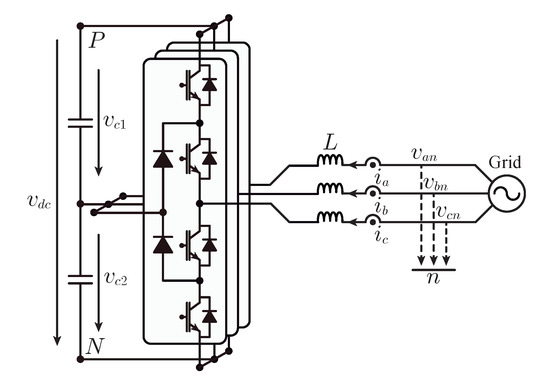
Figure 1.
The three-phase three-level NPC converter topology.

Table 1.
System Parameters.
According to the Kirchhoff‘s Voltage Law, the power converter voltages can be described as:
Suppose the ac system is balanced, that is, the sum of the ac currents as well as the sum of the ac voltages are equal to zero. Then the system model of the three-level NPC converter can be described as follows [29]:
where the variables is defined to simplify the controller design. Through the well-known Clarke transformation, the system model in the coordinates frame is also obtained.
Generally, the control scheme for the three-level NPC converter working as an AFE consists in the voltage regulator, power tracking and balancing control. The objectives can be briefly summed up as regulating the actual values towards their reference values, respectively, i.e., , and .
In the balancing loop, to assure the converter operates normally, the error voltage between the two capacitors is demanded to be near zero, i.e., . Normally, a simple PI controller is used in this loop to achieve this goal and alleviates the complexity of the whole control system although other techniques can be found in the literature [30,31].
In the inner loop, an effective ORS-DPC technique with the PI controller is employed for the purpose of active and reactive power tracking. Clearly, following the instantaneous power theory [32], the active and reactive power can be expressed as:
where , , and .
It can be noted that the active power P and reactive power Q should keep constant when the system comes to steady state, that is, and . According to the ORS-DPC theory [33], the operation point of the system can be presented using the average duty cycles based on the coordinate frame when the derivatives of instantaneous active and reactive powers equal to zero simultaneously. Therefore, the equivalent point can be derived as:
where . Taking into account the ORS theory and the equivalent point (6), a conventional PI controller is employed to enforce the instantaneous power tracking.
where , are the instantaneous power errors, as well as represent the corresponding PI controllers. Consequently, with the ORS-DPC technique, the instantaneous active and reactive powers are regulated to the equivalent point effectively. The detail of this method can be found in [33] and [34].
A particular emphasis is put on the voltage regulator. Traditionally, a PI controller is also utilized to regulate the dc-link voltage. The whole control block diagram of the traditional PI-based control scheme is given in Figure 2. In this paper, to enhance the performance of the voltage regulator, a adaptive STA control scheme plus HGO is proposed for the three-level NPC converter. Two features of the seminal solution are worth to be pointed out. Firstly, adaptive gains are used in the STA controller to limit the chattering phenomenon, which guarantees the fast response performance and simultaneously has no harm to the current and power quality. The second one lies in rejecting external disturbances, an efficient HGO is designed based on the adaptive STA control strategy to solve this problem. The control structure of the proposed adaptive STA plus HGO control strategy is presented in Figure 3.
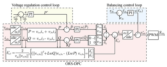
Figure 2.
Traditional PI-based control scheme for three-level NPC converter in AFE application.
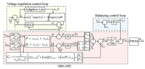
Figure 3.
Proposed HGO-Adaptive STA control strategy for three-level NPC converter in AFE application.
3. Principles of the HGO-Adaptive STA Control Strategy
3.1. High-Gain Observer
In this subsection, the HGO is introduced in the voltage regulation loop to deal with the external disturbances. In the three-phase NPC converter, clearly, a voltage drop occurs when the uncertain dc loads are connected to the dc side. In fact, a sudden power step is presented. Although a robust adaptive STA is designed in this work, the disturbance rejection ability is limited owing to the lack of disturbance information. For this reason, a efficient HGO is designed based on the adaptive STA method to reject the load perturbations.
It is assumed that all the loops are well controlled when the converter operates normally, that is, and . In the meantime, the losses of switching elements in the converter are ignored. After that, according to the power balance theory, the system Equation (2) in the dc side can be rewritten as,
where is a additional power, which is supposed to the power caused by dc loads here. For the convenience of observer design, Equation (8) can be indicated as,
where , , , , is the time derivative of the load power, y is the measured output.
Suppose that satisfies locally Lipschitz condition, and and are bounded. A HGO can be designed to estimate the disturbances
where represents a nominal model of , which is set to zero to simplify the observer design. Then the estimation errors and yields
where
To achieve the goal of asymptotic error convergence, is designed as Hurwitz. For this system, and are set as some positive constants to meet the requirements. In addition, due to the existence of in (11), the effect of on e should be considered. To alleviate this influence, the gains of the HGO can be designed as
where , and are positive constants which need to be designed, and . After that, the transfer function from on e can be obtained as follows,
Consequently, . The coefficient needs to be adjusted to a small value to reduce the sensitivity on and to estimate states rapidly.
Lemma 1.
[21] Assume that and are bounded, then for system (11), there is a scalar existed such that the following condition is satisfied
where.
Remark 1.
The coefficient ε can be set as a small value to increase the speed of estimation error decaying. In addition, through selecting ε sufficiently small, the boundary ζ can be given arbitrarily small [26]. However, in real applications, the effect of measured noise on HGO is increased when ε is set as a much small value. For this reason, the gains of the HGO should be designed carefully considering the trade-off between the sensitivity with respect to noise and the speed of state estimation. Finally, the estimated disturbance is added to the voltage regulation loop as a compensation. As a consequence, the output of the voltage regulator is adjusted according to the existing disturbances, which improves the disturbance rejection ability.
3.2. Adaptive Super-Twisting Algorithm
The proposed adaptive STA control strategy is addressed in detail in this subsection. The motivation is to improve the dynamic performance of the voltage regulator comparing with the conventional PI controller. Considering the dynamic model (9), it follows that
To design the controller, a sliding mode surface can be designed as
where . After that, it can be obtained
The designed controller can be divided as two parts, i.e., and . The can be given by , and is presented in (19) according to the adaptive STA controller [35]
where and are the adaptive gains and will be designed later. Then the whole controller yields
Substituting (20) to (18), it follows that
where , , . Note that, according to 1, the estimated error is bounded, then it can be obtained that the time derivative of is bounded and satisfies following condition
where is a positive constant.
Theorem 1.
Proof.
A strong Lyapunov function for the STA method is selected here according to [36],
For the sake of calculation, a new vector is defined as
After that, the Lyapunov function (25) can be rewritten in quadratic form
where
is symmetric positive definite. Note that and , and the time derivative of can be derived as
Considering Equation (29), and following the standard inequality , the derivative of the strong Lyapunov function yields
where
and represents the Euclidean norm, and respectively denote the minimum and maximum eigenvalues of matrices. Consequently, the system will converge to sliding mode manifold in finite time following the comparison theory [37] and condition (23). The maximum finite convergence time can also be calculated as
where is the initial state. ☐
It is worth mentioning that a trade-off exists between the fast transient response and chattering phenomenon if the parameters and are set as some positive constants. To overcome this difficulty, an adaptive STA control strategy is proposed in the voltage regulator to solve this problem with the idea of variable gains. In system (18), define with a bounded perturbation, that is
with the condition
where is the unknown boundary.
Lemma 2.
Remark 2.
There are two situations which are worth noting.
- S1.
- S2.
- . When it comes to this situation, owing to the fact that , the gains (α, β) will decrease immediately until the condition is satisfied. Afterwards, they will increase again as soon as is large than the boundary ρ, that is, it comes back to S1. Finally, the sliding mode variable s will remain in a domain . In the meantime, the gains are varying in zigzag if the system are operating at a steady state.
4. Experimental Verification
In order to demonstrate the advantages of the proposed controller scheme the NPC power converter laboratory prototype shown in Figure 4 has been used. The most important controller parameters as well passive elements values can be consulted in Table 2. The control objective of the dc-link voltage regulation is set as = 750 V, and the reference value of the reactive power is 0 kVar for the purpose of unity power factor.
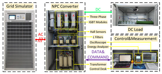
Figure 4.
NPC power converter laboratory experimental test bench.
Table 2.
Circuit and control parameters.
The proposed controller scheme has been evaluated in the laboratory prototype considering steady state operation point as well as transient state. Additionally, the proposal has been compared with traditional PI controller scheme. It should be noted that both two control strategies are tuned to the proper performance to assure a fair comparison. The conventional PI controller is tuned using the expert method [38]. The tuning process of the proposed HGO-Adaptive STA method consists in three steps. Firstly, the gains of the normal STA can be obtained with the approach provided by [8,39]. Secondly, the parameters in the adaptive law can be designed appropriately according to the analysis in Remark 2. Finally, a simple fine-tune process is required in the experiment to achieve the proper performance.
4.1. Steady State Performance
For steady state operation point, the power converter has been operated with a load connected consuming kW of active power. In this sense, both controller schemes have been compared in terms of quality of the grid currents, that are shown in Figure 5. Additionally, to make a fair comparison, the harmonic spectrum of currents measured by Fluke 434-II power analysis meter are also shown in Figure 6. As can be observed, both strategies present a similar performance in terms of the current waveform and total harmonic distortion.
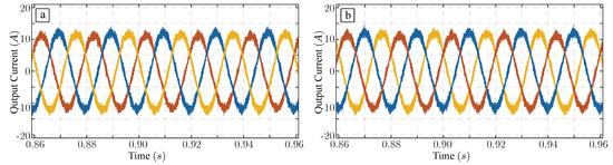
Figure 5.
NPC ac currents for a 5.3 kW load. (a) PI controller. (b) HGO-Adaptive STA proposed controller.
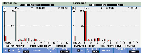
Figure 6.
NPC ac currents harmonic spectrum for a 5.3 load. (a) PI controller. (b) HGO-Adaptive STA proposed controller.
4.2. Transient Response
From transient behaviour point of view, the NPC power converter has been evaluated under two different operation scenarios.
On the one hand, the power converter has been operated under a voltage step. This experiment has been realized considering both strategies. As can be observed in Figure 7a, the experiment starts from a dc-link voltage equalling to 750 V in steady state and a new dc-link voltage reference of 700 V is applied in s. It is easy to deduced that the proposed HGO-Adaptive STA scheme presents a better performance in terms of tracking error as well as settling time. After few seconds of operation, the dc-link voltage reference is set to 750 V anew, and the corresponding transient waveforms are shown in Figure 7b. In this sense, the same conclusions can be extracted.
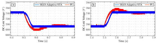
Figure 7.
NPC dc-link dynamic under a voltage step. (a) A voltage step from 750 V to 700 V; (b) A voltage step from 700 V to 750 V.
On the other hand, the performance of the proposed control scheme has been evaluated in terms of drop voltage after a dc load variation to test the disturbance rejection ability. For this, a 150 load has been connected during power converter operation as shown in Figure 8a. As can be observed, HGO-Adaptive STA controller improves the performance of traditional PI controller scheme in terms of drop voltage as well as recovery time, which indicates the rather high disturbance rejection ability of the proposed method. Additionally, two dc-link capacitor voltages with the proposed HGO-Adaptive STA method are also given in Figure 8b, which can be observed that the balancing performance is also achieved under a load step. The transient response of active and reactive power under this load steps are also given, which is presented in Figure 9. Clearly, the proposed HGO-Adaptive STA method achieves fast response in power variation simultaneously comparing with the PI controller.
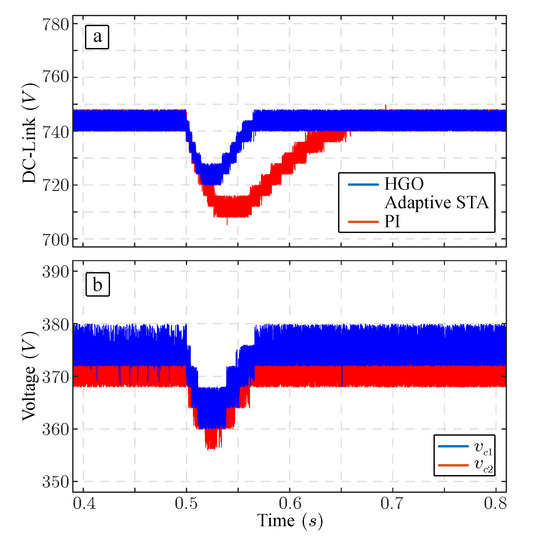
Figure 8.
NPC drop voltage in the dc side under a 150 load step. (a) DC-link voltage; (b) Two capacitor voltages with the proposed HGO-Adaptive STA strategy.
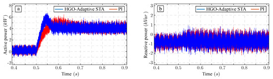
Figure 9.
NPC active and reactive power dynamics under a 150 load step. (a) Active power dynamics; (b) Reactive power dynamics.
5. Conclusions
In this paper, a HGO-based adaptive STA control strategy is proposed for the dc-link voltage control of NPC converters. To reject the external disturbances, a simple and efficient HGO is designed in the voltage regulation loop. By estimating the uncertain perturbations, the HGO compensates the disturbances information to the controller in real-time, which greatly enhances the disturbance rejection ability of the voltage regulator. On the other hand, a novel adaptive STA control strategy is also implemented in the voltage regulator. This approach reduces the chattering via the variable gains, which not merely guarantees the fast transient response of the voltage regulator, but also does not affect to the control performance of the inner loop. The proposed HGO-Adaptive STA control strategy has been compared with the conventional PI controller in a laboratory-scale three-level NPC prototype. The experimental results validate that the proposed HGO-Adaptive STA provides faster dynamic performance and better disturbances rejection ability of the voltage regulator. Consequently, based on these features above, the novel HGO-Adaptive STA approach is a very attractive solution for AFE applications.
Author Contributions
Conceptualization, X.S. and J.L.; writing—original draft preparation, X.S. and A.M.; writing—review and editing, J.I.L. and A.M.; supervision, J.L., W.L., S.V. and L.G.F. All authors have read and agreed to the published version of the manuscript.
Funding
This work was supported in part by the National Key R&D Program of China (No. SQ2019YFB130028), the National Natural Science Foundation of China (61525303, 41772377 and 61673130), Top-Notch Young Talents Program of China (Ligang Wu), State grid heilongjiang electric power company limited funded project and the Self-Planned Task of State Key Laboratory of Robotics and System (HIT) (SKLRS201806B). The authors gratefully acknowledge financial support provided by the Spanish Science and Innovation Ministry, and the Andalusian Government under projects TEC2016-78430-R and P18-RT-1340, respectively. Section II was made possible by NPRP 9-310-2-134 from the Qatar National Research Fund (a member of Qatar Foundation). The statements made herein are solely the responsibility of the authors.
Conflicts of Interest
The authors declare no conflict of interest.
Abbreviations
The following abbreviations are used in this manuscript:
| NPC | Neutral-Point-Clamped |
| AFE | Active Front-End |
| HGO | High-Gain Observer |
| STA | Super-Twisting Algorithm |
| SMC | Sliding Mode Control |
| ORS-DPC | Output Regulation Subspaces Based Direct Power Control |
| PI | Proportional Integral |
| KVL | Kirchhoff Voltage Law |
References
- Rodriguez, J.R.; Dixon, J.W.; Espinoza, J.R.; Pontt, J.; Lezana, P. PWM regenerative rectifiers: State of the art. IEEE Trans. Ind. Electron. 2005, 52, 5–22. [Google Scholar] [CrossRef]
- Song, Z.; Tian, Y.; Chen, W.; Zou, Z.; Chen, Z. Predictive Duty Cycle Control of Three-Phase Active-Front-End Rectifiers. IEEE Trans. Power Electron. 2016, 31, 698–710. [Google Scholar] [CrossRef]
- Leon, J.I.; Kouro, S.; Franquelo, L.G.; Rodriguez, J.; Wu, B. The Essential Role and the Continuous Evolution of Modulation Techniques for Voltage-Source Inverters in the Past, Present, and Future Power Electronics. IEEE Trans. Ind. Electron. 2016, 63, 2688–2701. [Google Scholar] [CrossRef]
- Leon, J.I.; Vazquez, S.; Franquelo, L.G. Multilevel Converters: Control and Modulation Techniques for Their Operation and Industrial Applications. Proc. IEEE 2017, 105, 2066–2081. [Google Scholar] [CrossRef]
- Yin, Y.; Liu, J.; Sánchez, J.A.; Wu, L.; Vazquez, S.; Leon, J.I.; Franquelo, L.G. Observer-Based Adaptive Sliding Mode Control of NPC Converters: An RBF Neural Network Approach. IEEE Trans. Power Electron. 2019, 34, 3831–3841. [Google Scholar] [CrossRef]
- Sebaaly, F.; Vahedi, H.; Kanaan, H.Y.; Moubayed, N.; Al-Haddad, K. Design and Implementation of Space Vector Modulation-Based Sliding Mode Control for Grid-Connected 3L-NPC Inverter. IEEE Trans. Ind. Electron. 2016, 63, 7854–7863. [Google Scholar] [CrossRef]
- Sebaaly, F.; Vahedi, H.; Kanaan, H.Y.; Moubayed, N.; Al-Haddad, K. Sliding Mode Fixed Frequency Current Controller Design for Grid-Connected NPC Inverter. IEEE Trans. Emerg. Sel. Topics Power Electron. 2016, 4, 1397–1405. [Google Scholar] [CrossRef]
- Tabart, Q.; Vechiu, I.; Etxeberria, A.; Bacha, S. Hybrid Energy Storage System Microgrids Integration for Power Quality Improvement Using Four-Leg Three-Level NPC Inverter and Second-Order Sliding Mode Control. IEEE Trans. Ind. Electron. 2018, 65, 424–435. [Google Scholar] [CrossRef]
- Barros, J.D.; Silva, J.F. Optimal Predictive Control of Three-Phase NPC Multilevel Converter for Power Quality Applications. IEEE Trans. Ind. Electron. 2008, 55, 3670–3681. [Google Scholar] [CrossRef]
- Mora, A.; Cárdenas-Dobson, R.; Aguilera, R.P.; Angulo, A.; Donoso, F.; Rodriguez, J. Computationally Efficient Cascaded Optimal Switching Sequence MPC for Grid-Connected Three-Level NPC Converters. IEEE Trans. Power Electron. 2019, 34, 12464–12475. [Google Scholar] [CrossRef]
- Vazquez, S.; Acuna, P.; Aguilera, R.P.; Pou, J.; Leon, J.I.; Franquelo, L.G. DC-Link Voltage Balancing Strategy Based on Optimal Switching Sequences Model Predictive Control for Single-Phase H-NPC Converters. IEEE Trans. Ind. Electron. 2019, in press. [Google Scholar] [CrossRef]
- Lin, F.; Tan, K.; Lai, Y.; Luo, W. Intelligent PV Power System With Unbalanced Current Compensation Using CFNN-AMF. IEEE Trans. Power Electron. 2019, 34, 8588–8598. [Google Scholar] [CrossRef]
- Chen, C.; Sun, Z. Fixed-time stabilisation for a class of high-order non-linear systems. IET Control Theory A 2018, 12, 2578–2587. [Google Scholar] [CrossRef]
- Liu, J.; Yin, Y.; Luo, W.; Vazquez, S.; Franquelo, L.G.; Wu, L. Sliding Mode Control of a Three-Phase AC/DC Voltage Source Converter Under Unknown Load Conditions: Industry Applications. IEEE Trans. Syst. Man Cy-S. 2018, 48, 1771–1780. [Google Scholar] [CrossRef]
- Wu, C.; Wu, L.; Liu, J.; Jiang, Z. Active Defense-Based Resilient Sliding Mode Control Under Denial-of-Service Attacks. IEEE Trans. Inf. Forensics Security 2020, 15, 237–249. [Google Scholar] [CrossRef]
- Liu, J.; Wu, L.; Wu, C.; Luo, W.; Franquelo, L.G. Event-triggering dissipative control of switched stochastic systems via sliding mode. Automatica 2019, 103, 261–273. [Google Scholar] [CrossRef]
- Sun, G.; Wu, L.; Kuang, Z.; Ma, Z.; Liu, J. Practical tracking control of linear motor via fractional-order sliding mode. Automatica 2018, 94, 221–235. [Google Scholar] [CrossRef]
- Levant, A. Chattering Analysis. IEEE Trans. Autom. Control 2010, 55, 1380–1389. [Google Scholar] [CrossRef]
- Levant, A. Sliding Order and Sliding Accuracy in Sliding Mode Control. Int. J. Control. 1993, 58, 1247–1263. [Google Scholar] [CrossRef]
- Utkin, V. Discussion Aspects of High-Order Sliding Mode Control. IEEE Trans. Autom. Control 2016, 61, 829–833. [Google Scholar] [CrossRef]
- Liu, J.; Vazquez, S.; Wu, L.; Marquez, A.; Gao, H.; Franquelo, L.G. Extended State Observer-Based Sliding-Mode Control for Three-Phase Power Converters. IEEE Trans. Ind. Electron. 2017, 64, 22–31. [Google Scholar] [CrossRef]
- Shen, X.; Liu, J.; Luo, W.; Leon, J.I.; Vazquez, S.; Marquez Alcaide, A.; Franquelo, L.G.; Wu, L. High-Performance Second Order Sliding Mode Control for NPC Converters. IEEE Trans. Ind. Informat. 2019; in press. [Google Scholar] [CrossRef]
- Utkin, V.I.; Poznyak, A.S. Adaptive sliding mode control with application to super-twist algorithm: Equivalent control method. Automatica 2013, 49, 39–47. [Google Scholar] [CrossRef]
- Esfandiari, F.; Khalil, H. Output feedback stabilization of fully linearizable systems. Int. J. Control. 1992, 56, 1007–1037. [Google Scholar] [CrossRef]
- Alfehaid, A.A.; Strangas, E.G.; Khalil, H.K. Speed control of Permanent Magnet Synchronous Motor using extended high-gain observer. In Proceedings of the 2016 American Control Conference (ACC), Boston, MA, USA, 6–8 July 2016; pp. 2205–2210. [Google Scholar]
- Khalil, H.K. High-Gain Observers in Feedback Control: Application to Permanent Magnet Synchronous Motors. IEEE Contr. Syst. Mag. 2017, 37, 25–41. [Google Scholar]
- Mercorelli, P. A Two-Stage Sliding-Mode High-Gain Observer to Reduce Uncertainties and Disturbances Effects for Sensorless Control in Automotive Applications. IEEE Trans. Ind. Electron. 2015, 62, 5929–5940. [Google Scholar] [CrossRef]
- Wang, F.; Wang, J.; Kennel, R.M.; Rodríguez, J. Fast Speed Control of AC Machines Without the Proportional-Integral Controller: Using an Extended High-Gain State Observer. IEEE Trans. Power Electron. 2019, 34, 9006–9015. [Google Scholar] [CrossRef]
- Escobar, G.; Leyva-Ramos, J.; Carrasco, J.M.; Galvan, E.; Portillo, R.C.; Prats, M.M.; Franquelo, L.G. Modeling of a three level converter used in a synchronous rectifier application. In Proceedings of the 2004 IEEE 35th Annual Power Electronics Specialists Conference, Aachen, Germany, 20–25 June 2004; Volume 6, pp. 4306–4311. [Google Scholar]
- Ventosa-Cutillas, A.; Montero-Robina, P.; Umbría, F.; Cuesta, F.; Gordillo, F. Integrated Control and Modulation for Three-Level NPC Rectifiers. Energies 2019, 12, 1641. [Google Scholar] [CrossRef]
- Umbría, F.; Gordillo, F.; Estern, F.G.; Salas, F.; Portillo, R.; Vázquez, S. Voltage balancing in three-level neutral-point-clamped converters via Luenberger observer. Control. Eng. Pract. 2014, 25, 26–44. [Google Scholar] [CrossRef]
- Akagi, H.; Aredes, M. Instantaneous power theory and applications to power conditioning; John Wiley & Sons: Hoboken, NJ, USA, 2017. [Google Scholar]
- Escobar, G.; Stankovic, A.M.; Carrasco, J.M.; Galvan, E.; Ortega, R. Analysis and design of direct power control (DPC) for a three phase synchronous rectifier via output regulation subspaces. IEEE Trans. Power Electron. 2003, 18, 823–830. [Google Scholar] [CrossRef]
- Portillo, R.; Vazquez, S.; Leon, J.I.; Prats, M.M.; Franquelo, L.G. Model Based Adaptive Direct Power Control for Three-Level NPC Converters. IEEE Trans. Ind. Informat. 2013, 9, 1148–1157. [Google Scholar] [CrossRef]
- Shtessel, Y.; Taleb, M.; Plestan, F. A novel adaptive-gain supertwisting sliding mode controller: Methodology and application. Automatica 2012, 48, 759–769. [Google Scholar] [CrossRef]
- Moreno, J.A.; Osorio, M. A Lyapunov approach to second-order sliding mode controllers and observers. In Proceedings of the 2008 47th IEEE Conference on Decision and Control, Cancun, Mexico, 9–11 December 2008; pp. 2856–2861. [Google Scholar]
- Khalil, H.K. Nonlinear systems, 3rd ed.; Prentice-Hall: Upper Saddle River, NJ, USA, 2002. [Google Scholar]
- Litt, J. An expert system to perform on-line controller tuning. IEEE Contr. Syst. Mag. 1991, 11, 18–23. [Google Scholar]
- Susperregui, A.; Martinez, M.I.; Zubia, I.; Tapia, G. Design and tuning of fixed-switching-frequency second-order sliding-mode controller for doubly fed induction generator power control. IET Electr. Power Appl. 2012, 6, 696–706. [Google Scholar] [CrossRef]


© 2020 by the authors. Licensee MDPI, Basel, Switzerland. This article is an open access article distributed under the terms and conditions of the Creative Commons Attribution (CC BY) license (http://creativecommons.org/licenses/by/4.0/).