Article

The Catenary Method as an Alternative to the Horizontal Directional Drilling Trajectory Design in 2D Space

by
Rafał Wiśniowski
,
Krzysztof Skrzypaszek
,
Paweł Łopata
* and
Grzegorz Orłowicz
*
Faculty of Drilling Oil and Gas, Department of Drilling and Geoengineering, AGH University of Science and Technology, Mickiewicza 30 Av., 30–059 Kraków, Poland
*
Authors to whom correspondence should be addressed.
Energies 2020, 13(5), 1112; https://doi.org/10.3390/en13051112
Submission received: 5 January 2020 / Revised: 23 February 2020 / Accepted: 28 February 2020 / Published: 2 March 2020

Abstract

:
An increase in demand for energy natural resources has stimulated the development of gas pipeline networks in Europe, as well as globally. Also, in Poland in recent years there has been a significant increase in natural gas consumption. Therefore, it is necessary to build new pipelines networks using dig and no–dig techniques. Horizontal Directional Drilling is one of the most popular trenchless technologies. The aim of this article is to present a new approach in the design of HDD trajectories in two–dimensional space (2D). A review of the trajectories used so far has been provided, offering calculation algorithms to determine their well path. Then, the original catenary method is proposed, taking into account natural deflection of casing pipes. Applicable formulas and computational algorithms have been given, together with a computational example which enables comparison of the classical design methodology with the new one. According to the authors, due to natural stress distribution, the catenary method allows the use of smaller pulling forces during installation and ensures longer pipeline life. Therefore, it should be used in industrial practice as an alternative to current designing methods.

1. Introduction

Horizontal Directional Drilling (HDD) is one of the most popular trenchless technologies. The HDD technology has revolutionized geoengineering drilling in cities and under natural obstacles where the use of classical dig methods is impossible. It enables the ability to perform underground pipeline installations, while overcoming natural or artificial obstacles such as streets, buildings, railways, rivers and lakes, as well as minimizing a negative impact on the natural environment.
Taking into account both environmental and economic factors, the HDD technology can currently be considered one of the few alternatives to the classical dig methods in the construction of underground installations for the transmission of natural resources; in particular, natural gas. Increasing development and interest in this technology is in line with current trends in Polish energy policy and changes taking place in the natural gas market, the consumption of which in Poland increases year by year. The increase in demand is caused, among other reasons, by newly built power plants such as the Combined Cycle Gas Turbine in the Żerań CHP in Warsaw, which will burn approximately 0.65 billion m3 of natural gas annually [1]. In addition to the energy sector, other industries also consume more and more gas: steel mills, refineries, ceramic factories, glassworks, and nitrogen plants. In 2018, Poland consumed about 18 billion m3 of natural gas, including 4 billion m3 from the national resources. The remaining quantity was imported but the import direction changed in comparison to previous years. Gas imported from Russia plays a smaller role (a decrease of 0.62 billion m3 compared to 2017). However, the import of LNG (liquefied natural gas) transported to the terminal in Świnoujście by sea is growing. In 2018, gas carriers from the USA, Qatar and Norway supplied over 2.71 billion m3 of LNG. This is an increase of 58.2% compared to 2017. At the end of 2022, also, the Baltic Pipe gas pipeline will be completed, ensuring transport of the natural gas extracted in Norway [2,3]. The above–described changes make it necessary to construct new and modernize the existing pipeline networks, taking into account, at the same time, urban infrastructure (roads, buildings) and the natural environment (rivers, protected areas).
The Horizontal Directional Drilling method dates back to the 1960s when Martin Cherrington built his own drill rig and formed Titan Contractors, a company specializing in utility road boring in Sacramento, California. The first Horizontal Directional Drilling application in history was made in 1971 under the Pajero river near Wotsonville, California, United States. A 180-meter long pass with the diameter of 100 mm was carried out by Titan Contractor under the leadership of Martin Cherrington [4,5,6,7].
Nowadays, wellbores with diameters ranging from 50 to 1200 mm and a length of up to 2000 m are the most popular. Polyethylene (PE), high density polyethylene (HDPE), PVC, and steel pipes are used [8,9,10].
Parallel to the conventional HDD method, the Intersect Drilling method is being developed, which involves drilling pilot holes from the start, and end points simultaneously. It is used for long boreholes drilled in difficult conditions, where classical drilling from the entry point to the exit point would be impossible [11,12,13].
Drilling equipment categories are presented in the Table 1 below:
Horizontal Directional Drilling consists of three stages [14,16,17,18]:
  • Pilot hole drilling
  • Reaming
  • Casing installation
Drilling a pilot hole is the most important part. The pilot hole is made according to the assumed trajectory design. Depending on the rock hardness, drilling works are performed with the use of an asymmetrical hydromonitor bit, a cutter bit, or a cogged bit. The rock is drilled hydraulically and mechanically. The trajectory of the well axis is constantly or periodically measured; the location of the probe in an antimagnetic connection (disposed right after the bit) is verified. Surface or subsurface radiometric cable or cableless telemetric navigation systems are used. The direction of drilling can be corrected by rotating the drill pipe by a predefined angle. In order to obtain the predicted final diameter, the borehole is widened one or more times [15,18,19].
After making a pilot borehole, the drilling bit is substituted in the borehole with a cutter or a milled reamer on the drill pipes. The reamer is introduced into the pilot borehole to enlarge the diameter of the existing well. In the process of reaming, drill pipes are successively added to proceed with reaming operations or to trip the casing [15,18,19].
The final stage of HDD is casing pullback. To do this, a reamer, rotary sub, and a head (tripped with the pipe) are disposed on the string. The rotary sub (swivel) prevents the system against rotations and torque of the drill pipes on the tripped casing [15,18,19].
The key element affecting the effectiveness and success of HDD drilling is the correct well trajectory design. A decision about the trajectory design is made based on the design data.
The following options are considered [20]:
  • design of Horizontal Directional Drilling trajectory in two–dimensional space, with the following variations:
    trajectory being a combination of straight and curvilinear sections
    chain curve trajectory (catenary)
    an irregular curve trajectory
  • design of Horizontal Directional Drilling trajectory in three–dimensional space
This article is dedicated to the Horizontal Directional Drilling trajectory design in two–dimensional space. A combination of straight and curvilinear sections and the chain curve trajectory (catenary) design will be examined.

2. Mathematical Foundations of a Horizontal Trajectory Design in a Plane Perpendicular to the Terrain Surface

2.1. Trajectories Being a Combination of Straight and Curvilinear Sections

One of the most commonly applied concepts of the Horizontal Directional Drilling trajectory design is a combination of straight and curvilinear sections. The simplest variant is a trajectory consisting of one curvilinear section with a constant radius of curvature. Next variants are a combination of different numbers of straight and curvilinear sections [18,20]. Figure 1 shows the most common types of trajectories.
Assuming a reference system (see Figure 2) in a plane perpendicular to the surface of the terrain, it is possible to determine general dependencies for the types of trajectories presented in Figure 1 [18].
General dependencies:
  • vertical displacement of the end point relative to the start point:
    H =   j = 1 n H j
  • horizontal displacement of the end point relative to the start point:
    A =   j = 1 n A j
  • trajectory length:
    L =   j = 1 n L j
  • azimuth.
Graphic interpretation of general dependencies is shown in Figure 3.
Curvilinear sections are defined by the following parameters:
  • radius of curvature:
    R j = 180 π DLS j ,
  • angle of curvature:
    δ j =   ε j ε j 1   for   ε j >   ε j 1 ,
    δ j =   ε j 1 ε j   for   ε j <   ε j 1  
  • projection of a trajectory section on a vertical plane:
    H j =   R j ( cos ε j 1 cos ε j ) ,   for   ε j >   ε j 1 ,
    H j =   R j ( cos ε j cos ε j 1 ) ,   for   ε j <   ε j 1   ,
  • projection of a trajectory section on a horizontal plane:
    A j =   R j ( sin ε j sin ε j 1 ) ,   for   ε j >   ε j 1 ,
    A j =   R j ( sin ε j 1 sin ε j ) ,   for   ε j <   ε j 1 ,
  • section length:
    L j = π 180 · δ j · R j   ,
Straight sections are determined by the following parameters:
  • projection of a trajectory section on a vertical plane:
    H j = L j · sin ε j   ,
  • projection of a trajectory section on a horizontal plane:
    A j = L j · cos ε j   ,
  • section length:
    L j = A j 2 + H j 2   ,
At the AGH University of Science and Technology in Krakow at the Drilling and Geoengineering Department, of Faculty Drilling, Oil and Gas, algorithms that enable calculation of characteristic points Pj (Aj, Hj) of any type of trajectory with different input data variants were created. The Department of Drilling and Geoengineering also presented an algorithm enabling the determination of intermediate Pi characteristic points Pi (Ai, Hi, εi, βi) with a given calculation step ΔL [18,20].
The most commonly used trajectory is a combination of straight and curvilinear sections consisting of 5 sections (see Figure 1e). Table 2 presents steps to determine characteristic values of a trajectory with the first variant of input data.
Based on the calculated characteristic values of trajectory sections, it is possible to determine spatial coordinates of intermediate points. To do this, the algorithm (see Figure 4) with the following assumptions should be used:
  • global left–handed Cartesian coordinate system with the origin at the entry point of the wellbore. Axis orientation: OX—east geographical, OY—north geographical, OZ—vertical
  • specified azimuth of the plane (β) constant for the whole trajectory (βL = β)
The value of the angle of deviation from the horizontal plane εL tangent to the trajectory at point PL lying between the characteristic points Pj–1 and Pj at the distance LL, measured from the beginning of the wellbore:
  • rectilinear section εj = εj–1
    ε L = ε j   ,
  • curvilinear section εj > εj–1
    ε L = ε j 1 + ( L L i = 1 j 1 L i ) · DLS j   ,
Spatial coordinates of point PL lying between characteristic points Pj–1 and Pj:
  • rectilinear section εj = εj–1
    X L = ( i = 1 j 1 A i + ( L L i = 1 j 1 L i ) · cos ε j ) · sin β   ,
    Y L = ( i = 1 j 1 A i + ( L L i = 1 j 1 L i ) · cos ε j ) · cos β   ,
    Z L = i = 1 j 1 H i + ( L L i = 1 j 1 L i ) · sin ε j   ,
  • curvilinear section εj > εj–1
    X L = { i = 1 j 1 A i + R j · [ sin ( ε j 1 + ( L L i = 1 j 1 L i ) · DLS j ) sin ε j 1 ] }   ,
    Y L = { i = 1 j 1 A i + R j · [ sin ( ε j 1 + ( L L i = 1 j 1 L i ) · DLS j ) sin ε j 1 ] }   ,
    Z L = { i = 1 j 1 H i + R j · [ cos ε j 1 cos ( ε j 1 + ( L L i = 1 j 1 L i ) · DLS j ) ] }   ,
The most important steps of the algorithm determining the trajectory being a combination of straight and curvilinear sections:
  • Determination of input data (A, H, L1, R2, R4, ε1, ε3, ε5) and a calculation step.
  • Calculation of the characteristic points according to the steps in Table 2.
  • Transfer of calculation results from point 2 and definition of additional variables.
  • Beginning of the iteration block associated with the hole section number.
  • Calculation of the current abscissa value rounded down to an integer.
  • Beginning of the nested iteration block. Check if variable X has not exceeded the range, if so, go to point 9.
  • Calculation of spatial coordinates X, Y and the alpha angle depending on the type of section.
  • Incrementation of loop variables and return to point 6.
  • Add to Hsum and Asum values corresponding to a given section. Increment the section.
  • Check if the section scope has not been exceeded, if not, return to step 4.
  • End of algorithm.

2.2. Chain Curve Trajectory (Catenary)

The second concept for designing Horizontal Directional Drilling trajectories is related to the natural deflection of the casing described by a chain curve (see Figure 5) [18,20]. A catenary curve is a natural curve that a cable, chain, or any other line of uniform weight assumes when suspended between two points. A similar suspension of a drill string would also form a catenary curve. A common example is a curve formed by a telephone line hanging between two utility poles. The catenary method was first introduced by R.T. McClendon and E.O. Anders [21]. In the oil and gas industry, the catenary method is often used to perform extended–reach wells. The application of this method has been described in detail in the literature [22,23,24]. The authors point out the benefits of casing natural deflection.
As casings used in HDD have diameters from several centimeters to a meter, and their length is up to over a thousand meters, it can be stated that the length of a pipe column is disproportionately larger than its diameter, which is why such a construction can be treated as a rope hanging between two poles.
In the model adopted in this way, there may be slight deviations associated with the assumption that the transverse bending and torsional stiffness is negligible in relation to longitudinal stiffness. Figure 6 shows a fragment of a free–hanging column of casing. In order to determine the relationship between the unit weight of the casing and its forces, section AB of the ds length, which is in equilibrium, is considered.
General dependencies:
Assuming that the casing is not susceptible to longitudinal deformations and its unit weight q is constant over the entire length, the chain curve equation in the system from Figure 6 is as follows:
ψ = N poz q cosh ( q N poz ( η + C 1 ) ) N poz q cosh ( q N poz ( C 1 ) )   ,
The relationship between the value of force Npoz and the constant C1 can be determined from the formula (23), using the condition: f(AK) = Hk (see Figure 6), which gives:
q N poz H k = cosh ( q N poz ( A k + C 1 ) ) cosh ( q N poz ( C 1 ) )   ,
Assuming the value of force Npoz equal to the pulling force of the drilling device, it is possible to determine the value of constant C1. Equation (24) is an implicit equation of variable Npoz. This type equation can be solved using numerical methods, e.g. bisection methods. The equation transforms into the form:
g ( x ) = cosh ( q N poz ( A k + x ) ) cosh ( q N poz ( x ) ) q N poz H k   ,
and then the zero of the function is determined.
Using the physical sense of the derivative of function Y at point 0 and the relationship between angles γ0 and ε0, the formula for constant C1 can be obtained:
C 1 = N poz q arcsinh ( tg ( ε 0 ) )   ,
To determine spatial coordinates and the angle of deviation from the horizontal plane of the trajectory described by a chain curve, the algorithm (see Figure 7) and the following assumptions should be used:
  • global right–handed Cartesian coordinate system with the origin at the entry point of the wellbore. Axis orientation: OX—east geographical, OY—north geographical, OZ—vertical.
  • specified azimuth of the plane (β) constant for the whole trajectory (βL = β)
The value of the angle of deviation from the horizontal plane εL tangent to the trajectory at point PL lying at a distance LL measured from the beginning of the wellbore:
ε L = arctg ( q N poz L L + sinh ( q N poz C 1 ) )   ,
Total length of the trajectory (n = Ak):
L K = N poz q sinh ( q N poz ( A k + C 1 ) ) N poz q sinh ( q N poz ( C 1 ) )   ,
The spatial coordinates of point PL with a given length step (∆L) can be determined using the transformed equations (27) and (28):
η = N poz q arcsin ( q N poz L L + sinh ( q N poz C 1 ) ) C 1   ,
ψ = N poz q cosh ( arcsinh ( q N poz L L + sinh ( q N poz C 1 ) ) ) N poz q cosh ( q N poz C 1 )   ,
and:
X L = η L · sin β   ,
Y L = η L · cos β   ,
Z L = ψ L ,

3. Calculation Example

Based on the presented equations and algorithms, an example of trajectory calculations was made.

3.1. Assumptions:

The distance between the entry point and the exit point in a horizontal projection: A = 1000 m.
Vertical displacement between the entry point and the exit point in a vertical projection: H = −15 m.
Azimuth: β = 0º

3.1.1. Chain Curve Trajectory (Catenary):

Casing weight: 500 N/m
Drilling rig pulling force: Npoz = 250000 kgf = 2451662.5 N

3.1.2. Trajectory Being a Combination of Straight and Curvilinear Sections:
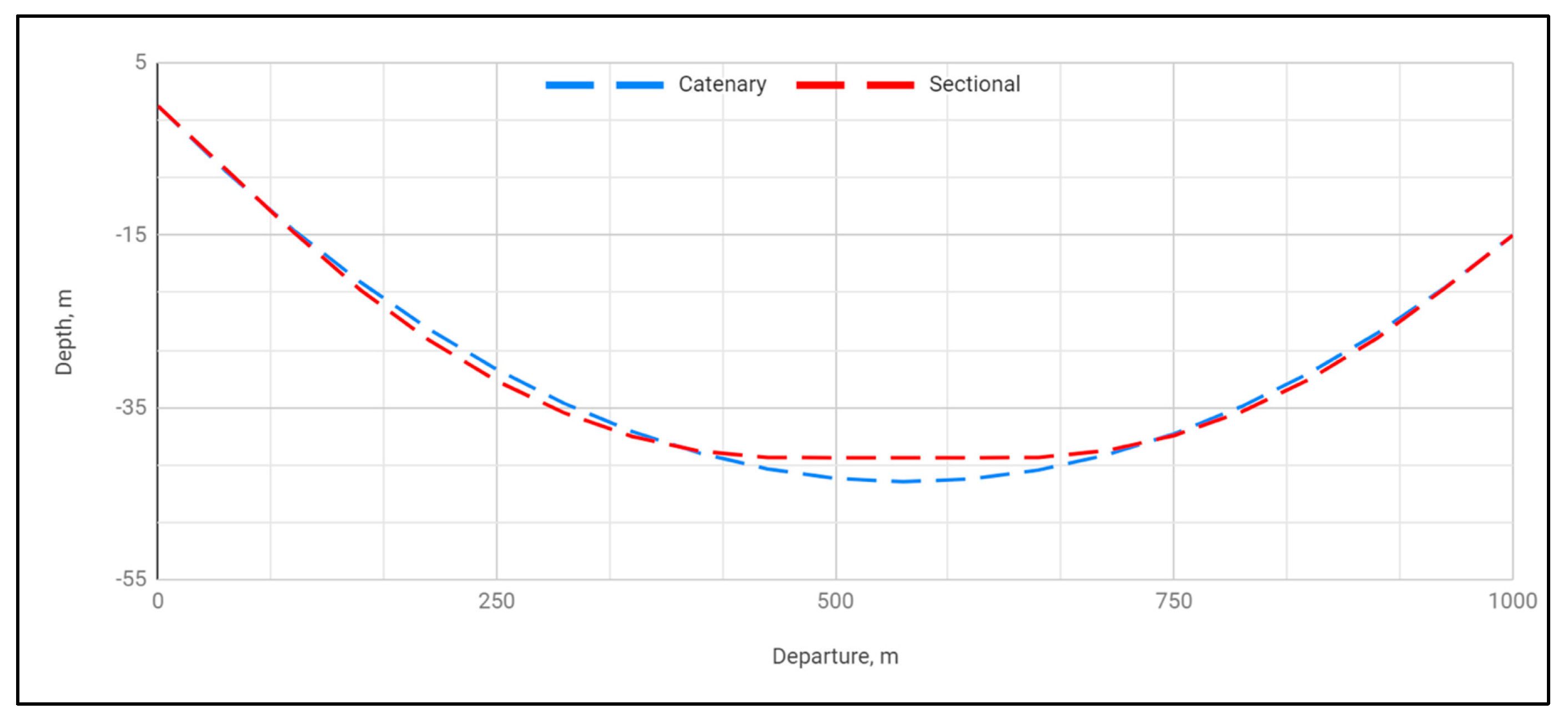
Radius of the 1st curve section: R2 = 2500 m
Radius of the 2nd curve section: R4 = 2500 m
Entry angle: ε1= –8.33°
Exit angle: ε5= 7°
First section length: L1 = 100 m

3.2. Results

The calculations were made using the designed computational library which implements the proposed algorithms. The simplified results were presented in tabular (see Table 3 and Table 4) and graphical (see Figure 8, Figure 9 and Figure 10) formats.

4. Conclusions

  • HDD is a dynamically developing technology for constructing underground pipelines This is due to the fact that this type of drilling can be performed in urban and hard–to–reach areas. Horizontal directional drilling is an alternative to microtunneling, direct pipe and jacking. At the same time, the HDD technology enables minimization of a negative impact on the environment compared to conventional methods.
  • A very attractive alternative to standard design solutions is the concept of a chain curve trajectory (catenary), which enables easier insertion of the pipeline into a wellbore and ensures its longer life due to the natural stress distribution along the length.
  • The algorithms developed by the authors of the article at the AGH University of Science and Technology at the Faculty of Drilling Oil and Gas should be used in practice, as they reduce costs, failures, and complications during well drilling using the HDD technology.
  • Based on given equations and project methodologies, the authors see the potential for expanding the topic in the area of trajectories optimization that will result in a trajectory that combines advantages of both design conceptions.

Author Contributions

Conceptualization, R.W., K.S., P.Ł., and G.O.; Methodology, R.W., K.S., P.Ł., and G.O.; Software, P.Ł., and G.O.; Validation, R.W., K.S., P.Ł., and G.O.; Formal Analysis, R.W., K.S., P.Ł., and G.O.; Investigation, R.W., K.S., P.Ł., and G.O.; Resources, R.W., K.S., P.Ł., and G.O.; Data Curation, R.W., K.S., P.Ł., and G.O.; Writing—Original Draft Preparation, R.W., K.S., P.Ł., and G.O.; Writing—Review & Editing, R.W., K.S., P.Ł., and G.O.; Visualization, R.W., K.S., P.Ł., and G.O.; Supervision, R.W. and K.S.; Project Administration, R.W. and K.S. All authors have read and agreed to the published version of the manuscript.

Funding

This research received no external funding.

Conflicts of Interest

The author declares no conflict of interest.

Nomenclature

Ajprojection of the jth section on a horizontal plane[m]
βazimuth[º]
DLSjdogleg severity[º/m]
δjangle of curvature at the jth point of the hole[º]
εjangle of deviation from horizontal plane at the jth characteristic point[º]
Hjprojection of the jth section/segment on a vertical plane[m]
Ljlength of jth section/segment[m]
Npozdrilling rig pulling force[N]

References

  1. Pgnig Termika. Blok Gazowo–Parowy na Żeraniu. (ang. Combined Cycle Gas Turbine in the Żerań CHP). Available online: https://termika.pgnig.pl/node/288 (accessed on 2 January 2020).
  2. Pgnig. 2018—Kolejny Rok Mniejszego Importu Gazu z Rosji i Większego Importu LNG—Portal Korporacyjny. (ang. 2018—Another Year of Smaller Gas Imports from Russia and Larger LNG Imports—Corporate Portal). Available online: http://pgnig.pl/aktualnosci/–/news–list/id/pgnig–2018–kolejny–rok–mniejszego–importu–gazu–z–rosji–i–wiekszego–importu–lng/newsGroupId/10184 (accessed on 2 January 2020).
  3. Baltic Pipe. Harmonogram Projektu. (ang. Project Schedule). Available online: https://www.baltic–pipe.eu/pl/o–baltic–pipe/harmonogram–projektu/ (accessed on 2 January 2020).
  4. Drilling Contractors Association. Available online: https://dca–europe.org/index.php/en/verband/hdd–technik (accessed on 2 January 2020).
  5. Farr, A. The Birth and Development of Horizontal Directional Drilling. Available online: https://trenchlesstechnology.com/brief–history–horizontal–directional–drilling/ (accessed on 2 January 2020).
  6. How the HDD Industry Began—By Martin Cherrington. Available online: http://www.trenchlessdataservice.com/library/dbhistory.htm (accessed on 2 January 2020).
  7. Zwierzchowska, A. Przewierty sterowane i przeciski pneumatyczne—Bezwykopowa budowa sieci podziemnych cz. 2. (ang. Guided boring and pneumatic jacking—Trenchless construction of underground networks part 2). Nowocz. Bud. Inż. 2006. Available online: http://yadda.icm.edu.pl/baztech/element/bwmeta1.element.baztech–cff9fb9e–4174–4a3c–889c–b56f60681dab (accessed on 2 January 2020).
  8. Lueke, J.S.; Ariaratnam, S.T. Numerical characterization of surface heave associated with horizontal directional drilling. Tunn. Undergr. Space Technol. 2006, 21, 106–117. [Google Scholar] [CrossRef]
  9. Stein, D.; Mölers, K.; Bielecki, R. Microtunelling; Vch Verlagsgesellschaft Mbh: Weinheim, Germany, 1989. [Google Scholar]
  10. Allouche, E.N.; Como, C. Horizontal directional drilling technology, techniques and applications. In Proceedings of the NASTT/Univ. of Alberta Technical Seminar on Trenchless Technology, Alberta, Canada, 5 December 1997; pp. 18–26. [Google Scholar]
  11. Australian Drilling Industry Training Committee Limited the Drilling Manual; CRC Press: Boca Raton, FL, USA, 2015; ISBN 978-0-429-15054-8.
  12. Peace River HDD Intersect Project. Available online: https://www.trenchlessinternational.com/2010/03/17/peace–river–hdd–intersect–project/ (accessed on 2 January 2020).
  13. Wiśniowski, R.; Druzgała, A.; Formela, M.; Toczek, P. Intersect Drilling Method; SGEM: Vienna, Austria, 2018; Volume 18. [Google Scholar]
  14. Jariwala, S.; Pitroda, J.; Bhavsar, J. Horizontal Directional Drilling: New Era for Underground Utilities. In Proceedings of the National Conference CRDCE13, SVIT, Vasad, India, 20–21 December 2013. [Google Scholar]
  15. Wiśniowski, R.; Ziaja, J. Projektowanie wielkogabarytowych horyzontalnych przewiertów sterowanych. (ang. Design of large–size Horizontal Directional Drilling). Wiert. Nafta Gaz 2007, 1, 609–618. [Google Scholar]
  16. Bielecki, R.; Schreyer, J. Guidelines for Selecting Construction Methods for Eart–Laid Lines under Environmentally Relevant and Economic Aspects. Gstt–Dokumentation. Trenchless Layning And Repairing Pipes In Germany; GSTT: Hamburg, Germany, 1997. [Google Scholar]
  17. Willoughby, D. Horizontal Directional Drilling: Utility and Pipeline Applications; McGraw–Hill: New York, NY, USA, 2005; ISBN 978-0-07-145473-5. [Google Scholar]
  18. Wiśniowski, R.; Stryczek, S. Projektowanie trajektorii horyzontalnego przewiertu sterowanego. (ang. Horizontal Directional Drilling trajectory design). Wiert. Nafta Gaz 2007, 2, 929–941. [Google Scholar]
  19. Wiśniowski, R.; Ziaja, J. Methods of determining admissible bending radius for HDD drill string. Acta Montan. Slov. 2004, 9, 340–343. [Google Scholar]
  20. Wiśniowski, R. Selected Aspects of Directional Wells Construction Design with the Use of Numeric Methods; AGH: Kraków, Poland, 2002. [Google Scholar]
  21. McClendon, R.T. Directional drilling using the catenary method. In Proceedings of the SPE/IADC Drilling Conference, New Orleans, Louisiana, 5–8 March 1985. [Google Scholar] [CrossRef]
  22. Liu, X.; Samuel, R. Catenary well profiles for ultra extended–reach wells. Proc. SPE Annu. Tech. Conf. Exhib. 2009, 3. [Google Scholar] [CrossRef]
  23. Aadnoy, B.S.; Toff, V.; Djurhuus, J. Construction of ultralong wells using a catenary well profile. In Proceedings of the IADC/SPE Drilling Conference, Miami, FL, USA, 21–23 February 2006. [Google Scholar] [CrossRef]
  24. Hui, L.; Yan, W.; Juan, W.; Zhongming, L.; Tao, X. Long horizontal section of horizontal well section optimization design research. Res. J. Appl. Sci. Eng. Technol. 2013, 6, 156–159. [Google Scholar] [CrossRef]
Figure 1. Horizontal directional drilling trajectories as a combination of straight and curvilinear sections: (a) one curvilinear section; (b) straight section and one curvilinear section; (c) two straight sections and one curvilinear section; (d) straight section and two curvilinear sections; (e) three straight sections and two curvilinear sections.
Energies 13 01112 g001
Figure 2. Reference system used when designing HDD trajectories in two–dimensional space.
Energies 13 01112 g002
Figure 3. General geometric dependencies.
Energies 13 01112 g003
Figure 4. Simplified algorithm for determining the spatial coordinates of trajectories being a combination of straight and curvilinear sections.
Energies 13 01112 g004
Figure 5. Chain curve trajectory.
Energies 13 01112 g005
Figure 6. Geometric dependencies for the section of 9a free hanging casing [20].
Energies 13 01112 g006
Figure 7. Simplified algorithm for calculating spatial points of the catenary trajectory.
Energies 13 01112 g007
Figure 8. Catenary trajectory.
Energies 13 01112 g008
Figure 9. Trajectory being a combination of straight and curvilinear sections.
Energies 13 01112 g009
Figure 10. Comparison of the catenary trajectory and the trajectory being a combination of straight and curvilinear sections.
Energies 13 01112 g010
Table 1. Horizontal Directional Drilling (HDD) equipment categories [14,15].
CategoryType of EquipmentPulling Force [kN]Torque [Nm]Power [kW]Maximum Mud Flow Rate [l/min]Type of Horizontal Drilling
1very small<100<2500<75100Small
2small100–250<2500–1500075–150500Medium
3medium250–50015000–25000150–3001000
4large500–100025000–50000300–6001500Large
5extra large>1000>50000>600>1500
Table 2. The order of calculating the characteristic values for a trajectory consisting of 5 sections with the given input parameters: A, H, L1, ε1, ε3, R2, R4 [20].
Variant I: A, H, L1, ε1, ε3, ε5, R2, R4
StepValue to be calculatedStepValue to be calculated
1H111DLS4
2A112L4
3H213L3
4A214H3
5δ215A3
6DLS216H5
7L217A5
8H418L5
9A419L
10δ4
Table 3. Catenary trajectory results.
[i]XYε
000−9
150−7.55−8.2
2100−14.39−7.39
3150−20.5−6.59
4200−25.9−5.78
5250−30.58−4.97
6300−34.54−4.16
7350−37.79−3.34
8400−40.32−2.53
9450−42.14−1.71
10500−43.24−0.89
11550−43.63−0.08
12600−43.310.74
13650−42.271.56
14700−40.522.38
15750−38.063.19
16800−34.884.01
17850−30.984.82
18900−26.375.63
19950−21.056.44
201000−157.24
Table 4. Results for the trajectory being a combination of straight and curvilinear sections.
[i]XYε
000−8.33
150−7.32−8.33
2100−14.64−8.3
3150−21.42−7.15
4200−27.17−5.99
5250−31.91−4.84
6300−35.64−3.69
7350−38.37−2.54
8400−40.09−1.4
9450−40.81−0.25
10500−40.830
11550−40.830
12600−40.830
13650−40.80.3
14700−40.031.45
15750−38.262.6
16800−35.493.75
17850−31.724.89
18900−26.936.05
19950−21.147
201000−157

