New Cell Balancing Charging System Research for Lithium-ion Batteries


Abstract
:1. Introduction
2. Proposed Method
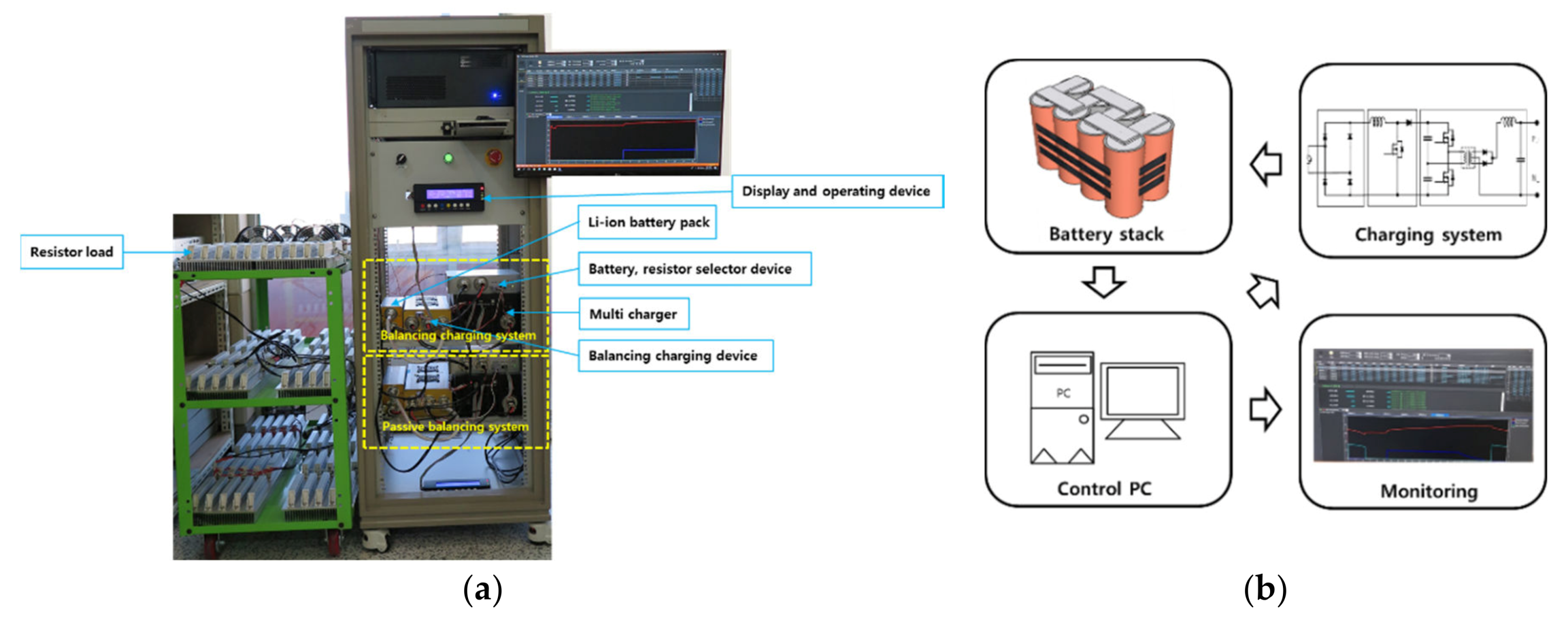
2.1. Hardware
2.2. Software
3. Experiments
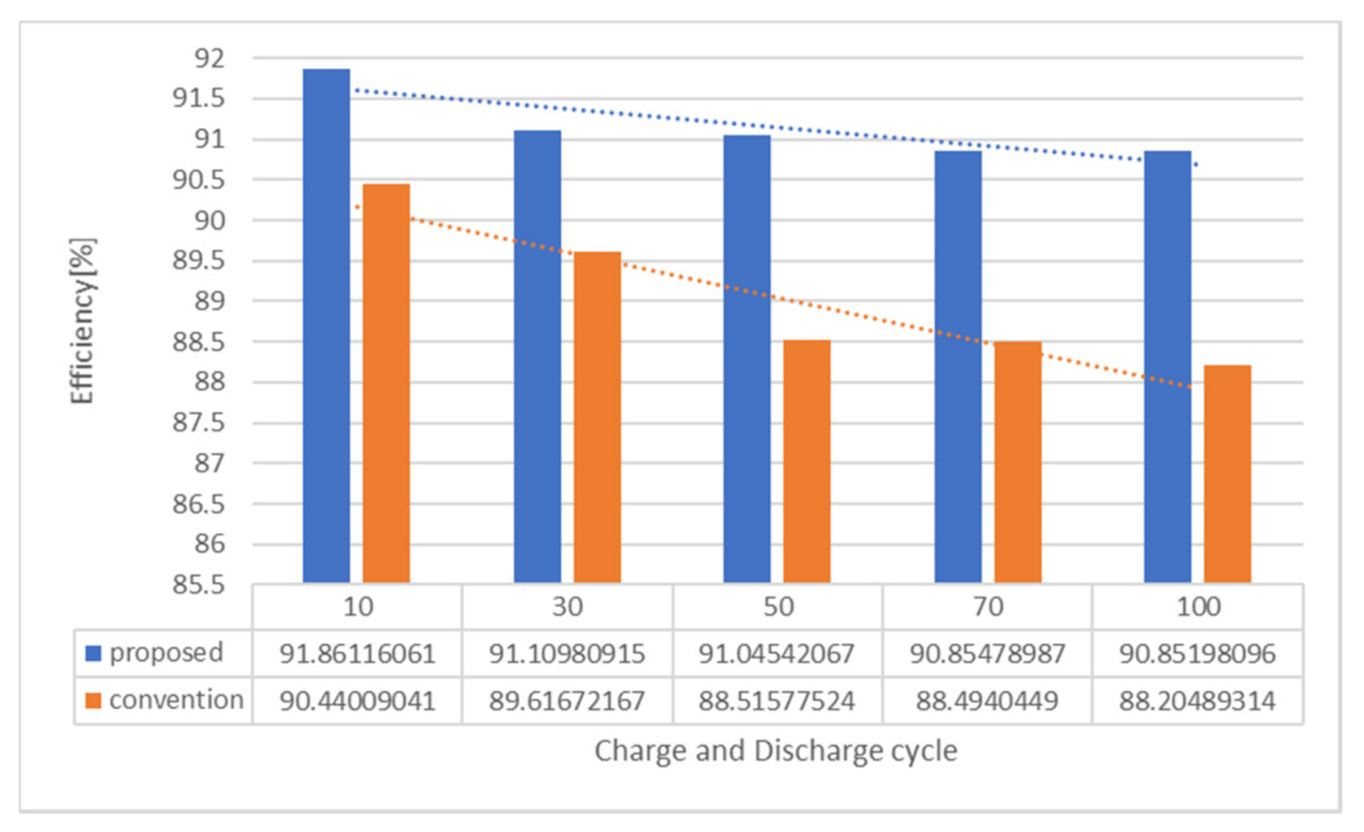
4. Results and Discussion
5. Conclusions
Author Contributions
Funding
Conflicts of Interest
References
- Linden, D.; Reddy, T.B. Handbook of Batteries, 3rd ed.; Linden, D., Ed.; McGraw-Hill Professional: New York, NY, USA, 2001; pp. 35.1–35.90. [Google Scholar]
- Shin, D.; Poncino, M.; Macii, E.; Chang, N. A statistical model of cell-to-cell variation in Li-ion batteries for system-level. In Proceedings of the International Symposium on Low Power Electronics and Design (ISLPED), Beijing, China, 4–6 September 2013. [Google Scholar]
- Nagasubramanian, G.; Jhngst, R.G. Energy and power characteristics of lithium-ion cells. J. Power Sources 1998, 72, 189–193. [Google Scholar] [CrossRef]
- Xing, Y.; Ma, E.W.M.; Tsui, K.L.; Pecht, M. Battery management systems in electric and hybrid vehicles. Energies 2011, 4, 1840–1857. [Google Scholar] [CrossRef]
- Antonio, M.; Andrea, A.; Alessandro, M.; Sergio, M.S.; Angelo, G. A new BMS architecture based on cell redundancy. IEEE Trans. Ind. Electron. 2011, 58, 4314–4322. [Google Scholar]
- Krein, P.T.; Balog, R. Life extension through charge equalization of lead-acid batteries. In Proceedings of the INTELEC, International Telecommunications Energy Conference, Montreal, QC, Canada, 29 September–3 October 2020. [Google Scholar]
- Habiballah, R.E.; Unnati, O.; Federico, B.; Mo-Yuen, C. Battery management system: An overview of its application in the smart grid and electric vehicles. IEEE. Ind. Electron. Mag. 2013, 7, 4–16. [Google Scholar] [CrossRef]
- Zheng, Y.; Ouyang, M.; Lu, L.; Li, J.; Han, X.; Xu, L. On-line equalization for Lithium-ion battery packs based on charging cell voltages: Part 1: Equalization based on remaining charging capacity estimation. J. Power Sources 2014, 247, 676–686. [Google Scholar] [CrossRef]
- Donghwa, S.; Massimo, P.; Cnrico, M.; Naehyuck, C. A statistical model-based cell-to-cell variability management of li-ion battery pack. IEEE Trans. Comput. Aided Des. Integr. Circuits Syst. 2015, 34, 252–265. [Google Scholar] [CrossRef]
- Omariba, Z.B.; Zhang, L.; Sun, D. Review of battery cell balancing methodologies for optimizing battery pack performance in electric vehicles. IEEE Access 2019, 7, 129335–129352. [Google Scholar] [CrossRef]
- Javier, G.L.; Enrique, R.C.; Isabel, M.M.; Miguel, G.M. Battery equalization active methods. J. Power Sources 2014, 246, 934–949. [Google Scholar]
- Kim, M.-Y.; Kim, C.-H.; Cho, S.-Y.; Moon, G.-W. A cell selective charge equalizer using multi-output converter with auxiliary transformer. In Proceedings of the 8th International Conference on Power Electronics—ECCE Asia, Jeju, Korea, 30 May–3 June 2011; pp. 310–317. [Google Scholar]
- Baughman, A.C.; Ferdowsi, M. Double-tiered switched-capacitor battery charge equalization technique. IEEE Trans. Ind. Electron. 2008, 55, 2277–2285. [Google Scholar] [CrossRef]
- Sang-Hyun, P.; Ki-Bum, P.; Hyoung-Suk, K.; Gun-Woo, M.; Myung-Joong, Y. Single-magnetic cell-to-cell charge equalization converter with reduced number of transformer windings. IEEE Trans. Power Electron. 2011, 27, 2900–2911. [Google Scholar] [CrossRef]
- Yunlong, S.; Naxin, C.; Qi, Z.; Chenghui, Z. Abattery equalizer with zero-current switching and zero-voltage gap among cells based on three-resonant-state LC converters. In Proceedings of the 2017 IEEE Applied Power Electronics Conference and Exposition (APEC), Tampa, FL, USA, 26–30 March 2017. [Google Scholar]
- Khan, A.B.; Choi, W. Optimal charge pattern for the high-performance multistage constant current charge method for the Li-ion batteries. IEEE Trans. Energy Convers. 2018, 33, 1132–1140. [Google Scholar] [CrossRef]
- Kim, M.Y.; Kim, C.H.; Kim, J.H.; Moon, G.W. A chain structure of switched capacitor for improved cell balancing speed of Lithium-ion batteries. IEEE Trans. Ind. Electron. 2014, 61, 3989–3999. [Google Scholar] [CrossRef]
- Broussely, M.; Herreyre, S.; Biensan, P.; Kasztejna, P.; Nechev, K.; Staniewicz, R.J. Aging mechanism in Li ion cells and calendar life predictions. J. Power Sources 2001, 97–98, 13–21. [Google Scholar] [CrossRef]


| Charging Method | Charging Energy | Discharging Energy | Efficiency |
|---|---|---|---|
| Passive Charging | 1,239,589 J | 1,085,535 J | 87.57% |
| Proposed Charging | 1,238,119 J | 1,093,640 J | 88.33% |
| Item | Part | Cost | Remarks |
|---|---|---|---|
| Passive BMS cell unit | FET | $0.5 | 10EA: $18.0 |
| 1 Watt resistance | $0.3 | ||
| ETC | $1.00 | ||
| Controller | LTC6804 | $10.00 | Multicell battery monitors |
| ETC | $10.00 | ||
| Battery | 42V10A(10S4P) | $240.00 | Li-ion 18650 2600mA |
| Total cost | $278.00 |
| Item | Part | Cost | Remarks |
|---|---|---|---|
| Proposed system cell unit | DRV8870DDA | $1.20 | 10EA: $63 |
| ACS714LLCTR-50A-T | $1.00 | ||
| Transformer 3:1 (2A) | $1.00 | ||
| B340A/SMA | $1.10 | ||
| ETC | $2.00 | ||
| Controller | ST SMT32F746 | $5.00 | MCU |
| ETC | $20.00 | ||
| Battery | 42V10A(10S4P) | $240.00 | Li-ion 18650 2600mA |
| Total cost | $328.00 |
© 2020 by the authors. Licensee MDPI, Basel, Switzerland. This article is an open access article distributed under the terms and conditions of the Creative Commons Attribution (CC BY) license (http://creativecommons.org/licenses/by/4.0/).
Share and Cite
Zun, C.-Y.; Park, S.-U.; Mok, H.-S. New Cell Balancing Charging System Research for Lithium-ion Batteries. Energies 2020, 13, 1393. https://doi.org/10.3390/en13061393
Zun C-Y, Park S-U, Mok H-S. New Cell Balancing Charging System Research for Lithium-ion Batteries. Energies. 2020; 13(6):1393. https://doi.org/10.3390/en13061393
Chicago/Turabian StyleZun, Chan-Yong, Sang-Uk Park, and Hyung-Soo Mok. 2020. "New Cell Balancing Charging System Research for Lithium-ion Batteries" Energies 13, no. 6: 1393. https://doi.org/10.3390/en13061393