Abstract
Numerical calculations are performed to determine the potential of using one-dimensional transparent photonic crystal heat mirrors (TPCHMs) as transparent coatings for solar receivers. At relatively low operating temperatures of 500 K, the TPCHMs investigated herein do not provide a significant advantage over conventional transparent heat mirrors that are made using transparent conducting oxide films. However, the results show that TPCHMs can enhance the performance of transparent solar receiver covers at higher operating temperatures. At 1000 K, the amount of radiation reflected by a transparent cover back to the receiver can be increased from 40.4% to 60.0%, without compromising the transmittance of solar radiation through the cover, by using a TPCHM in the place of a conventional transparent mirror with a In2O3:Sn film. For a receiver operating temperature of 1500 K, the amount of radiation reflected back to the receiver can be increased from 25.7% for a cover that is coated with a In2O3:Sn film to 57.6% for a cover with a TPCHM. The TPCHM that is presented in this work might be useful for high-temperature applications where high-performance is required over a relatively small area, such as the cover for evacuated receivers or volumetric receivers in Sterling engines.
1. Introduction
The worldwide solar thermal capacity has grown by a factor of 7.7 from 60 GWth in 2000 to 480 GWth in 2018, and these growth rates are expected to accelerate as replacing fossil fuels becomes increasingly important [1]. Ideally, a solar thermal collector should be strongly absorbing over the incident solar spectral region, where ~0.3 μm < λ < ~2.5 μm, while also preventing thermal radiation, with ~2.5 μm < λ < ~25 μm, from escaping. The exact wavelength region over which reducing thermal radiation losses is more important than achieving high solar absorption depends on the operating temperature of the collector, as the peak wavelength position of the thermal radiation spectra decreases with an increasing temperature. In practical applications, solar thermal collectors are realized using solar selective surfaces with wavelength dependent absorption properties; these surfaces are highly absorbing over the solar spectral region and they exhibit low emissivity values for thermal radiation with longer wavelengths. Solar selective surfaces are well-developed and they have been commonly realized using cermets, metal oxides, metals coated with thin-films comprising dielectric/metal/dielectric sandwich structures or semiconductors, and metal surfaces textured on the micron scale [2,3,4,5,6,7]. While a wide range of selective surfaces that absorb solar energy are available for different applications, their transparent counterparts are underdeveloped [8]. Transparent selective surfaces, or “transparent heat mirrors”, are technologically desirable for the advancement of concentrated solar technologies that employ volumetric receivers [9,10,11,12,13]. In practice, two types of transparent heat mirrors have been developed: ultrathin metal films that are sandwiched between thin-film dielectric antireflective coatings and doped transparent conducting oxides [14,15,16]. However, the transmittance of heat mirrors comprising thin metal films is not high enough for solar thermal applications. Consequently, the performance of doped TCOs is limited, because their transmissivity for solar radiation and high reflectivity towards thermal radiation are both dependent on their doping concentration; increasing the doping level of TCOs increases their reflectance towards thermal radiation, but it decreases their transmissivity towards solar radiation and, consequently, a trade-off between these two desirable attributes must be compromised [17,18].
Another emerging approach for realizing transparent heat mirrors is to fabricate them in the form of photonic structures [19,20,21]. For example, dielectric mirrors, otherwise referred to as one-dimensional photonic crystals, have a periodic structure in the direction normal to their surface and they are comprised of alternating thin-film layers with differing indices of refraction [22]. The wave interference phenomenon caused by interactions between incident light waves and the interfaces within the periodic structure prevents light with certain wavelengths from propagating through the structure. In three-dimensional photonic crystals this spectral region over which light is forbidden from propagating is referred to as a photonic band-gap, while in a one-dimensional photonic crystal it is referred to as a photonic stop-gap. Light with wavelengths within the photonic stop-gap that is incident from the normal direction will undergo complete reflection. In this regard, an advantage of one-dimensional photonic crystals over their two- and three-dimensional counterparts is their broad stop-band in the normal direction, which can be designed to intensely reflect incident radiation over a broad spectral range, which is advantageous for solar energy applications [23,24,25,26]. The objective of this work is to determine whether transparent heat mirrors can be made through structural design at the length scale of the photons these heat mirrors interact with, rather than tailoring their atomic composition through doping. That is, we consider structing transparent oxides on the length scale of the photons that the heat mirrors will interact with rather than using doped TCOs to achieve a balance between high transmission of solar irradiation and reflectance of thermal radiation. More specifically, we investigate the potential of using one-dimensional photonic crystals for the application of transparent heat mirrors.
2. Materials and Methods
Figure 1a shows the application of a transparent photonic crystal heat mirror (TPCHM). The objective of the TPCHM is to maximize the solar gain in the receiver while minimizing its thermal radiation losses. The solar power that is absorbed by the receiver is given as Pin = G·t·a·A, where G is the concentrated incident solar irradiance, t is the transmission of the TPCHM, a is the absorption of the receiver, and A is the surface area of the receiver. The radiation that is emitted from the receiver can be written as Prad = εeff·σ·T4·A, where σ is the Stefan–Boltzmann constant, and T is the receiver temperature. Furthermore, the emissivity of the receiver, ε, is the ratio of energy radiated from its surface compared to the amount of energy that it would radiate if it were a black body at the same temperature. For simplicity, we assume that the receiver is a blackbody with an emissivity that is equal to 1 and define an effective emissivity, εeff = 1 − r, for the receiver when it is covered by the TPCHM, where r is the fraction of thermal radiation that is reflected by the TPCHM back to the receiver.
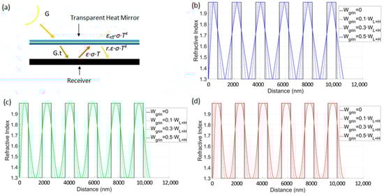
Figure 1.
(a) Schematic diagram of a solar receiver with a transparent heat mirror cover. Refractive index profile of one-dimensional (1-D) transparent photonic crystal heat mirrors with (b) linear (HL[LLHL]5), (c) cubic (HC[LCHC]5), and (d) quintic (HQ[LQHQ]5) interfacial profiles for different Wgrin values equal to 0.1·WL+H to 0.5·WL+H.
In this work, we are interested in the effects of the optical properties of the TPCHM on the temperature of the receiver T. Thus, we disregard convective and conductive heat losses, and thermal losses are assumed to be entirely radiative. Notably, these assumptions are valid when the operating temperature of the receiver is high and when the space between the receiver and the transparent heat mirror is vacuum or at low pressures. Moreover, thermal radiation that is emitted from the TPCHM is neglected, as the temperature of the receiver is much greater than that of the heat mirror during operation. Under these assumptions, at steady state Pin = Prad and the temperature of the receiver is given as:
Assuming that the receiver absorbs all of the solar radiation incident onto its surface, such that a = 1 over the solar spectral region, the temperature of the receiver is then given as T = C·(t/εeff)¼, where C is a constant that depends on the concentration ratio of the incident solar radiation and (t/εeff)¼ is a factor comprised of the optical material properties of the TPCHM. That is, the factor (t/εeff)¼ determines the temperature of the receiver for a given solar irradiance or, conversely, this factor determines the amount of incident solar irradiance that is required to achieve a desired receiver operating temperature.
One-dimensional TPCHMs can be realized by fabricating dielectric mirrors while using materials that are transparent to solar radiation and designing the thicknesses and indices of refraction of their constituent layers to produce a photonic stop-gap for thermal radiation. However, a challenge that arises is higher order reflection peaks that reduce transmission through the structure in the visible spectral region. One method of increasing transmission at a surface is to use the graded refractive index profiles that change gradually, rather than an abrupt step-profile at a flat surface. In this regard, Southwell has shown that the transmission can be greatly increased by introducing linear, cubic, and quintic, graded index of refraction profiles at a surface [27]. For Southwell’s gradient-index antireflection coatings, the linear, cubic, and quintic index of refraction profiles are described by polynomials of degree one, three, and five, respectively.
In this work, we show that one-dimensional TCPHMs can be designed in the form of dielectric mirrors, wherein Southwell’s graded index profiles are implemented at the interfaces between the layers within the dielectric mirrors. The periodicity of the dielectric mirrors can be designed as a quarter-wave stack that reflects thermal radiation, while interfacial graded refractive index profiles are used within the structure to ensure high levels of transmittance for solar radiation.
Figure 1b–d show the refractive index profiles of one-dimensional TCPHMs. The TPCHM with a linearly graded refractive index profile at the interface between the layers with the higher and lower indices of refraction, denoted as HL[LLHL]5, is shown in Figure 1b. In this notation, the H and L represent the thin films within the structure that have the higher and lower indices of refraction, while the subscript, L, and the superscript, 5, indicate that the interfacial index of refraction between the thin-films within the structure is linear and that there are five bi-layers within the structure, respectively. A final high index layer, HL, is deposited on [LLHL]5 to improve reflection, and, thus, the TCPHM shown in Figure 1b is denoted as HL [LLHL]5.
Herein, we assume the index of refraction of the H layer is 2.0, which is close to the index of refraction of many transparent oxides. Likewise, the index of refraction of the L layers is assumed to be 1.3, which is representative of porous optical films, such as silica nanoparticle films, which can be highly transmissive when made with small nanoparticles with a size of ~10 nm [28]. Furthermore, the TPCHMs are assumed to reside above a receiver that is operating at a temperature of 500 K. The reflectance peak position of the TPCHM is set to coincide with the peak of the radiation spectra emitted from a blackbody at 500 K, which is 5800 nm, to reflect the greatest amount of thermal radiation. That is, the thicknesses of the H (n = 2.0) and L (n = 1.3) layers within the dielectric mirror are set to 725 nm and 1115 nm, respectively, to form a quarter-wave stack with a reflectance peak at λ = 5800 nm. Moreover, the subscript “5800” is appended to the notation for the TPCHM to indicate that its first order Bragg reflectance peak has been set at 5800 nm. That is, H[LH]55800 represents a TPCHM without graded interfaces and with a first order Bragg-reflectance peak at 5800 nm. The width of the interfacial region that has a graded index of refraction profile between the H and L films within the structures, being denoted herein as Wgrin, is a design dependent parameter with a value of 0 ≤ Wgrin ≤ 0.5WL+H, where WL+H is the width of one bilayer within the TPCHM.
The index of refraction profiles for HL[LLHL]5 with Wgrin = 0, 0.1·WL+H, 0.3·WL+H, and 0.5·WL+H, are shown in Figure 1b, and it can be noted that when Wgrin = 0 the index of refraction profile is equivalent to that of a quarter wave stack, which is denoted as H[LH]5 and shown as the black line in Figure 1b–d. Following the same notation, the refractive index profiles for the TPCHMs with cubic and quintic interfacial profiles, which are represented as HC[LCHC]5 and HQ[LQHQ]5, are shown in Figure 1c,d, respectively, for the cases in which Wgrin = 0, 0.1·WL+H, 0.3·WL+H, and 0.5·WL+H.
In this work, thin film theory [29,30] is implemented in MATLAB code and applied to calculate the reflectance, transmittance, and temperature-determining factor, t/εeff, for the 1-D TPCHMs that are shown in Figure 1. The calculations were performed by increasing the wavelength of the solar and thermal radiation in increments of 10 nm. The graded refractive index profiles were divided into 20 discrete layers to perform the calculations, wherein the optical properties of these layers is constant. Approximating each graded interface as 20 layers with increasing/decreasing indices of refraction is sufficient; for example, increasing to 100 layers resulted in a change in the reflectance and transmittance values of less than 1%.
Unless stated otherwise, the solar irradiance and thermal radiation were assumed to be incident from the normal direction to simplify the calculations. In general, the solar irradiance transmitted and thermal radiation reflected by a receiver cover depend on the geometry of the receiver and the cover. In this work, we present the transmittance and reflectance in arbitrary units (a.u.). Furthermore, the solar spectrum is assumed to be the radiation spectrum that is emitted by a black body at a temperature of 5800 K. Moreover, for all calculations performed in this work, it is assumed the incident media is air (nair = 1) and the TPCHM resides on a semi-infinite glass substrate (nglass = 1.52). The glass substrate is assumed to be semi-infinite to avoid wave interference effects between the layers within the TPCHM and the bare side of the glass substrate. The implication of this assumption is that the transmittance of solar radiation through the TPCHM is overestimated by a few percent, because reflection from the substrate surface without the TPCHM is not taken into account (for example, the refection from the surface of a glass substrate is 4% and this can be reduced by applying an anti-reflective coating). The optimal Bragg reflectance peak positions for the TPCHMs were iteratively determined by calculating the value of t/εeff, as the Bragg peak positions were changed in increments of 10 nm. The Bragg peak positions that maximized t/εeff were selected as the optimum values.
3. Results and Discussion
Figure 2a shows the reflectance for H[LH]55800, HL[LLHL]55800, HC[LCHC]55800, and HQ[LQHQ]55800, for the case when Wgrin = 0.5·WL+H, over the spectral region extending from 100 to 10,000 nm. H[LH]55800 exhibits the broadest and most intense Bragg reflection peak, with a full width at half maximum (FWHM) value of 2140 nm and a peak reflectance value of 5800 nm. When considering the TPCHMs with graded interfacial refractive index profiles, HQ[LQHQ]55800 has the most intense Bragg-reflectance peak, with a full width at half maximum (FWHM) value of 1860 nm and a peak reflectance value of 5950 nm.
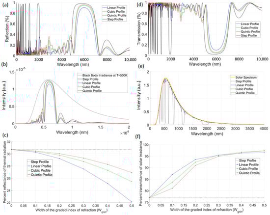
Figure 2.
(a) Reflectance spectra for H[LH]55800, HL[LLHL]55800, HC[LCHC]55800, and HQ[LQHQ]55800. (b) The portion of the radiation spectrum emitted from a black body at a temperature of 500 K that is reflected from H[LH]55800, HL[LLHL]55800, HC[LCHC]55800, and HQ[LQHQ]55800. (c) The percentage of radiation from a blackbody at 500 K that is reflected from H[LH]55800 (shown as the flat dashed line), HL[LLHL]55800, HC[LCHC]55800, and HQ[LQHQ]55800 plotted as a function of Wgrin. (d) Transmittance spectra for H[LH]55800, HL[LLHL]55800, HC[LCHC]55800, and HQ[LQHQ]55800. (e) The solar irradiance transmitted through H[LH]55800, HL[LLHL]55800, HC[LCHC]55800, and HQ[LQHQ]55800. (f) The percentage of solar irradiance transmitted through H[LH]55800 (shown as the flat dashed line), HL[LLHL]55800, HC[LCHC]55800, and HQ[LQHQ]55800 plotted as a function of Wgrin.
The radiation spectra emitted from a blackbody at 500 K, and the amount of this radiation that is reflected by H[LH]55800, HL[LLHL]55800, HC[LCHC]55800, and HQ[LQHQ]55800, for the case when Wgrin = 0.5·WL+H, is shown in Figure 2b. Moreover, the percentage of this blackbody radiation that is reflected by HL[LLHL]55800, HC[LCHC]55800, and HQ[LQHQ]55800 is plotted in Figure 2c as a function of Wgrin. As shown in Figure 2c, H[LH]55800 reflects 30.7% of the radiation that is emitted from a blackbody at 500 K (indicated as the value for Wgrin = 0), while the amount of radiation reflected by HL[LLHL]55800, HC[LCHC]55800, and HQ[LQHQ]55800 decreases to 22.1%, 25.5%, and 26.9%, respectively, as Wgrin increases from 0 to 0.5·WL+H.
For the TPCHMs considered herein, the greatest amount of blackbody reflection is achieved using H[LH]55800, however H[LH]55800 transmits the least amount of solar radiation. The transmittance spectra for H[LH]55800, HL[LLHL]55800, HC[LCHC]55800, and HQ[LQHQ]55800, for the case when Wgrin = 0.5·WL+H, is shown for the spectral region extending from 100 to 10,000 nm in Figure 2d. A number of intense dips in the transmittance spectra of H[LH]55800, being caused by higher order Bragg-reflectance peaks, can be seen over the solar spectral region. In comparison, the dips in the transmittance spectra over the solar spectral region are much less pronounced for HL[LLHL]55800, HC[LCHC]55800, and HQ[LQHQ]55800. The interfacial graded index of the refraction profiles within HL[LLHL]55800, HC[LCHC]55800, and HQ[LQHQ]55800 increase the transmission of light with wavelength in the solar spectral range, thereby mitigating the effects of the higher order Bragg-reflectance peaks. For light with longer wavelengths, such as where the blackbody emission peak occurs at 5800 nm, the interfacial graded index of refraction profiles ‘appears’ to be closer to that of a quarter-wave step profile. At these longer wavelengths, the first order Bragg-reflectance peak is retained by HL[LLHL]55800, HC[LCHC]55800, and HQ[LQHQ]55800, although with some reduction in intensity in comparison to H[LH]55800.
The solar spectrum and solar radiation that were transmitted through H[LH]55800, HL[LLHL]55800, HC [LCHC]55800, and HQ[LQHQ]55800, for the case when Wgrin = 0.5·WL+H, are shown in Figure 2e, while the percentage of the solar irradiance transmitted through HL[LLHL]55800, HC[LCHC]55800, and HQ[LQHQ]55800 is plotted in Figure 2f as a function of Wgrin. As shown in Figure 2f, H[LH]55800 just transmits 76.9% of the solar irradiance (indicated as the value for Wgrin = 0), while the percentage of solar radiation that is transmitted by HL[LLHL]55800, HC[LCHC]55800, and HQ[LQHQ]55800 increases to 96.5%, 97.4%, and 97.3%, respectively, as Wgrin increases from 0 to 0.5·WL+H.
The results that are presented in Figure 2 show that high solar transmittance values can be achieved for the TPCHMs presented herein when Wgrin = 0.5·WL+H. However, it is desirable to increase the amount of blackbody radiation that is reflected by these TPCHMs, and this can be achieved by stacking multiple TPCHMs on top of each other. For example, when considering HQ[LQHQ]55800, which transmits more solar radiation than H[LH]55800 while reflecting more blackbody radiation than HL[LLHL]55800 or HC[LCHC]55800, two or three TPCHMs could be stacked to form HQ[LQHQ]5λ1·HQ[LQHQ]5λ2 or HQ[LQHQ]5λ1·HQ[LQHQ]5λ2·HQ[LQHQ]5λ3. Here, the “λx” subscripts indicate the position of the quarter wave stack Bragg-reflectance peak of the xth TPCHM in the stacked structure in nanometers. In this work, the “λx” values are the optimal Bragg-peak reflectance positions that maximize (t/εeff)¼. In the remaining sections of this paper we consider TPCHMs, wherein the interfaces between the high and low- index of refraction layers have either a step profile or a quintic profile (the value of t/εeff TPCHMs, wherein the interfacial index of refraction profiles are linear or cubic are in between that for TPCHMs with interfacial step and quintic profiles).
Figure 3a shows the radiation from a black body receiver at 500 K reflected by H[LH]55790·H[LH]57060·H[LH]59540, and HQ[LQHQ]55790·HQ[LQHQ]57560·HQ[LQHQ]510390. The percentage of radiation reflected by H[LH]55790·H[LH]57060·H[LH]59540 is 74.8% and that reflected by HQ[LQHQ]55790·HQ[LQHQ]57560·HQ[LQHQ]510390 is 62.7%. While the radiation reflected from these two TPCHMs is comparable, a higher value of t/εeff is attained for HQ[LQHQ]55790·HQ[LQHQ]57560·HQ[LQHQ]510390, because it transmits a greater portion of the solar irradiance. That is, the solar irradiance transmitted through H[LH]55790·H[LH]57060·H[LH]59540, and HQ[LQHQ]55790·HQ[LQHQ]57560·HQ[LQHQ]510390, as shown in Figure 3b, is 50.9% and 96.6%, respectively.

Figure 3.
(a) The radiation emitted from a black body at 500 K and the amount of this radiation that is reflected by H[LH]55790·H[LH]57060·H[LH]59540, and HQ[LQHQ]55790·HQ[LQHQ]57560·HQ[LQHQ]510390. (b) The solar irradiance transmitted through H[LH]55790·H[LH]57060·H[LH]59540, and HQ[LQHQ]55790·HQ[LQHQ]57560·HQ[LQHQ]510390.
The results presented thus far have been for normally incident solar radiation onto TPCHMs that are comprised of bi-layers with L = 1.3, and H = 2. Furthermore, the operating temperature of the blackbody receiver beneath the TPCHM is 500 K. Alterations in these conditions and variables will alter the performance and temperature determining factor, t/εeff, of the TPCHMs. For example, t/εeff increases as the index of refraction contrast between the H and L layers within the TPCHM increases. On the other hand, the transmittance and overall reflectance of the TPCHMs does not significantly change as the angle of incident radiation is increased from 0° to 50°. The peak reflectance position of the TPCHMs decreases from 5800 nm to about 5300 nm as the angle of incident radiation increases from 0° to 50°; however, the broadband thermal radiation from the 500 K blackbody is still effectively reflected at these larger incident angles. In fact, the percentage of radiation from a black body at 500 K that is reflected by H[LH]55800, HL[LLHL]55800, HC[LCHC]55800, and HQ[LQHQ]55800 decreases by less than 5% as the angle of incidence of the radiation increases from 0° to 50°. Furthermore, the percentage of solar radiance that is transmitted through H[LH]55800, HL[LLHL]55800, HC[LCHC]55800, and HQ[LQHQ]55800 also decreases by less than 5% as the angle of incident radiation is increased from 0° to 50°. As the incident angle increases further, beyond 50°, the performance of the TPCHMs decreases because a large amount of the incident solar radiation is reflected. For example, for an incident angle of 80°, the solar transmittance decreases by ~25% while the amount of reflected radiation increases by ~15% as compared to these values for the case of normal incidence.
Thus far, the TPCHMs that are discussed herein were designed to work with a solar receiver operating at a temperature of 500 K. In general, TPCHMs can be designed to work with solar receivers that operate at a given temperature, T = Tx. For example, a quarter-wave dielectric mirror can be designed, wherein the thicknesses of its H and L layers are set to position its Bragg reflectance peak to coincide with the peak of the radiation spectra emitted from a receiver operating at Tx. The interfacial index of refraction profiles can then be designed to be graded. The optimal peak position for each mirror within the stack can be iteratively determined for cases in which the TPCHM is comprised of stacked dielectric mirrors. As an example, Figure 4 shows the radiative losses for receivers operating at 500 K, 1000 K, and 1500 K, that are covered with TCPHMs that have been optimized for these operating temperatures. The interfaces within the TCPHMs considered in Figure 4 have a graded index of refraction with a quintic profile, which provide for the highest values of t/εeff considering the TPCHMs discussed with reference to Figure 1. Moreover, Figure 5 shows the percentage of the solar irradiance transmitted and thermal radiation reflected from TPCHMs covering receivers at operating temperatures of 500 K, 1000 K, and 1500 K. The percentage of the solar irradiance transmitted and thermal radiation reflected by a conventional transparent heat mirror, namely a 0.32 μm thick In2O3:Sn film deposited via e-beam evaporation, is also shown in Figure 5 for comparison [31]. Furthermore, Figure 5a–c show the value of t/εeff when the blackbody receiver is at an operating temperature of 500 K, 1000 K, and 1500 K, respectively, for each receiver cover that was considered.
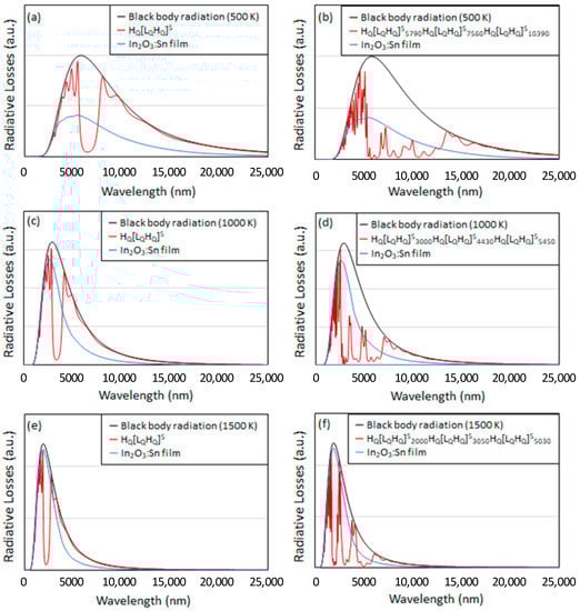
Figure 4.
The radiation spectra from a blackbody receiver at (a) 500 K, (b) 1000 K, and (c) 1500 K when it is not covered (black line), when it is covered with a In2O3:Sn film (blue line) and when it is covered with HQ[LQHQ]5. Also shown is the radiation spectra from a blackbody receiver at (d) 500 K, (e) 1000 K, and (f) 1500 K when it is not covered (black line), when it is covered with a In2O3:Sn film (blue line) and when it is covered with HQ[LQHQ]55790·HQ[LQHQ]57060·HQ[LQHQ]59540 (red line in “d”), HQ[LQHQ]53000·HQ[LQHQ]54430·HQ[LQHQ]55450 (red line in “e”), and HQ[LQHQ]52000·HQ[LQHQ]53050·HQ[LQHQ]55030 (red line in “f”).
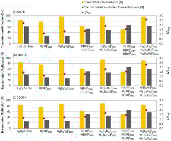
Figure 5.
The percentage of the solar irradiance transmitted through a In2O3:Sn reference film and single and triple-stacked transparent photonic crystal heat mirrors (TPCHMs) (yellow bars) in comparison to the percentage of radiation from a black body (gray bars) at (a) 500 K, (b) 1000 K, and (c) 1500 K that is reflected by these films. For all cases, the value of t/εeff is indicated by the red diamonds (right axis).
Figure 4a shows the spectral radiation losses from a receiver at 500 K covered with HQ[LQHQ]5. For comparison, the radiation losses for the case in which the receiver is covered with the In2O3:Sn reference film is also shown. The amount of radiation lost through the HQ[LQHQ]5 and In2O3:Sn covers is 73.1% and 38.5% for the HQ[LQHQ]5 and In2O3:Sn covers, respectively. The amount of radiation lost can be reduced to 37.3% by using a triple-stack configuration wherein HQ[LQHQ]55790·HQ[LQHQ]57560·HQ[LQHQ]510390 is used as the receiver cover, as shown in Figure 4b. Thus, the triple-stack TPCHM offers just a slight advantage over the In2O3:Sn cover when the receiver is operating at a temperature of 500 K. As shown in Figure 5a, the value of t/εeff for a black body receiver at 500 K is 2.19 when it is covered with the In2O3:Sn reference film, while t/εeff = 2.59 when the receiver is covered with HQ[LQHQ]55790·HQ[LQHQ]57560·HQ[LQHQ]510390. For all other TPCHMs that are considered in Figure 5a (other than HQ[LQHQ]55790·HQ[LQHQ]57560·HQ[LQHQ]510390), the value of t/εeff is less than that for the case of the In2O3:Sn reference film.
The emission losses through HQ[LQHQ]55800 and HQ[LQHQ]53000·HQ[LQHQ]54430·HQ[LQHQ]55450, which are optimized for a receiver operating at 1000 K, are shown in Figure 4c,d, respectively. Likewise, radiative losses through HQ[LQHQ]55800 and HQ[LQHQ]52000·HQ[LQHQ]53050·HQ[LQHQ]55030, optimized for a receiver operating temperature of 1500 K, are shown in Figure 4e,f, respectively. As the operating temperature of the receiver increases its black body radiation spectra shifts to shorter wavelengths and, for high enough operating temperatures, begins to overlap with the incident solar radiation spectra. At these higher operating temperatures, the performance of conventional transparent heat mirrors, such as the In2O3:Sn reference film, decreases, because these films transmit a larger portion of the blackbody radiation emitted by the receiver. That is, conventional transparent heat mirrors do not exhibit a sharp cut-off and they transmit solar radiation, but are highly reflective towards radiation that is emitted from a receiver at temperatures of 1000 K or higher. On the other hand, the TPCHMs that are discussed in this work can be designed to simultaneously exhibit higher transmittance of solar radiation and reflectance of radiation from receivers operating at these higher temperatures. For example, HQ[LQHQ]53000·[LQHQ]54430·[LQHQ]55450 transmits 90.9% of the solar irradiance, as compared to 84.4% transmitted by the In2O3:Sn reference film, as shown in Figure 5b. At the same time, HQ[LQHQ]53000·[LQHQ]54430·[LQHQ]55450 reflects 60.0% of the radiation from a receiver operating at 1000 K, while, in comparison, the In2O3:Sn reference film reflects just 40.4%. Also shown in Figure 5b, t/εeff = 1.42 when the In2O3:Sn reference film is used as the cover for a receiver at 1000 K, and t/εeff increases to 2.27 when HQ[LQHQ]53000·[LQHQ]54430·[LQHQ]55450 is used as the cover.
The advantage of the TPCHM cover the In2O3:Sn reference film is more pronounced when the operating temperature is 1500 K. As shown in Figure 5c, HQ[LQHQ]52000·[LQHQ]53050·[LQHQ]55030 and the In2O3:Sn reference film transmit approximately the same amount of solar radiation; 84.4% for the In2O3:Sn reference film as compared to 84.1% for HQ[LQHQ]52000·[LQHQ]53050·[LQHQ]55030. However, HQ[LQHQ]52000·[LQHQ]53050·[LQHQ]55030 reflects 57.6% of the radiation from the 1500 K receiver, while, in comparison, the In2O3:Sn reference film reflects just 25.7%. Furthermore, as shown in Figure 5c, t/εeff = 1.14 when the In2O3:Sn reference film is used as the cover for a receiver at 1500 K, and t/εeff increases to 2.98 when HQ[LQHQ]53000·[LQHQ]54430·[LQHQ]55450 is used as the cover. Notably, t/εeff = 1.65 when HQ[LQHQ]52410[LQHQ]53760 is used to cover a receiver operating at 1500 K.
The results that are presented herein show that using TPCHMs for the application of transparent heat mirrors can improve the performance by decreasing the effective emissivity at higher temperatures. However, fabricating these TPCHMs presents a challenge due to their number of layers and the level of precision that is needed to achieve the required refractive index profiles throughout the structure. While fabrication of thin-films with graded index profiles is challenging, a variety of methods for fabricating high-quality thin-films with a range of optical properties, including oblique angle deposition, plasma-enhanced chemical vapor deposition, and sol-gel processes exist and they are presently being developed for greater control over film properties [32,33,34,35,36,37,38,39]. Furthermore, recent research has been directed towards the development of transparent films with very low indices of refraction, such as mesoporous and aerogel films [40,41,42,43]. Future research will focus on using low-index films to reduce the number of layers required for fabricating the TPCHMs because the amount of thermal radiation they reflect increases with increasing contrast between their high- and low-index of refraction layers. Furthermore, the films modelled in this work are assumed to be non-absorbing, and the performance of the TPCHM decreases as the absorbance of their constituent layers increases. The materials that are selected for TPCHM fabrication should have low absorbance (e.g. k ~ 0.01) up to about 15 μm and 10 μm for receiver operating temperatures of 1000 K and 1500 K, respectively [44]. Notably, doping is not required when fabricating films within the TPCHM, because high reflectance (or low effective emissivity) for thermal radiation is achieved through the macroscopic structuring of these dielectric mirrors, rather than by tuning their free electron concentration. Moreover, in practical applications, material dispersion must be taken into consideration, because achieving a low effective emissivity requires a high contrast in the index of refraction between the materials within the TPCHM over the broad spectral wavelength region over which reflection of thermal radiation is required. As can be noted from the width of the radiation spectra for black bodies at 500 K, 1000 K, and 1500 K, as in Figure 4, the width of the spectral range over which high contrast is required decreases as the temperature of the receiver increases. On the other hand, high contrast between the constituent materials within the TPCHM is not required for achieving high solar transmittance.
Another important point to consider is the temperature that the TPCHMs will reach during operation. In this work it is assumed that the radiative losses from the TPCHM are small, because their temperature is assumed to be much lower than that of the receiver during operation. It is desirable for the TPCHM to be kept at low temperatures, not only to reduce thermal radiation losses, but also to avoid unwanted thermal effects, such as thermal expansion and degradation of the refractive index profile of the layers within the TPCHM. In practical solar thermal applications, low transparent heat mirror cover temperatures are readily achievable for the case of evacuated solar collectors, while it is challenging to maintain lower window temperatures in the design volumetric solar collectors.
As a more practical example, we also considered TPCHMs that were made from ZnSe and SiO2 nanoparticle films. We performed numerical calculations to determine the solar transmittance, thermal reflectance, and the value of t/εeff for TPCHM covers working with a receiver operating at a temperature of 1500 K. The optical properties for ZnSe and SiO2 up to a wavelength of 14 μm were attained from the literature [45,46,47,48]. The emission spectra from a blackbody at 1500 K peaks at ~1.9 μm and becomes negligible for wavelengths greater than 14 μm, as shown in Figure 4e. The optical properties for SiO2 nanoparticle films were estimated by taking a weighted average of the optical properties of air and solid SiO2, where it was assumed that the composition of these films is 30% air and 70% SiO2 by volume. For this example, ZnSe was selected, because it has a high refractive index over the infrared spectral region of interest (for example the index of refraction of ZnSe is ~2.4 over the spectral range extending from 2 μm to 14 μm). This relatively high index of refraction of ZnSe has good contrast in comparison to the index of refraction of the SiO2 nanoparticle films, which have an index of refraction equal to 1.32 at 1.9 μm. The results from this analysis show that the optimum value of t/εeff occurs when the Bragg-reflectance peak position for TPCHMs comprised of ZnSe and SiO2 nanoparticle films are at 1960 nm and 2086 nm in the case of interfacial step- and quintic-profiles, respectively. The solar transmittance for H[LH]51960 and HQ[LQHQ]52086 are 65.2% and 75.6%, respectively. Furthermore, 40.3% and 37.4% of the thermal radiation emitted from a blackbody at 1500 K is reflected from H[LH]51960 and HQ[LQHQ]52086, respectively. The values of t/εeff associated with H[LH]51960 and HQ[LQHQ]52086 are 1.09 and 1.21, respectively, and, in comparison t/εeff = 1.14 for the In2O3:Sn reference film. Thus, for the case of a blackbody receiver operating at 1500 K, the In2O3:Sn reference film outperforms H[LH]51960, while HQ[LQHQ]52086 exhibits the highest performance. In this example, H[LH]51960 did not perform as well as the In2O3:Sn reference film, because it reflects a large amount of the incident solar radiation, which is caused by the relatively high index of refraction of ZnSe. However, the graded interfacial profiles within HQ[LQHQ]52086 decrease the reflectance of solar radiation, which allows for a significantly larger amount of solar radiation to be transmitted through the TPCHM and absorbed by the receiver. The improved solar transmittance due to the structure of HQ[LQHQ]52086 enables this TPCHM to outperform the In2O3:Sn reference film.
4. Conclusions
In conclusion, the work that is presented herein demonstrates the advantages of using photonic structures to design transparent heat mirrors for solar energy harvesting applications. Specifically, the work investigates the application of dielectric mirrors for the application of transparent solar selective surfaces that reflect thermal radiation. For relatively low operating temperatures, when the receiver is at 500 K, the transparent photonic crystal heat mirrors that are described in this work do not offer significant advantages over conventional transparent heat mirrors, such as In2O3:Sn films. However, at operating temperatures of 1000 K or higher, the photonic crystal heat mirrors significantly enhance the amount of thermal radiation reflected back to a solar receiver. For example, the amount of thermal radiation that is reflected from a receiver at a temperature of 1500 K can be increased from 25.7% to 57.6% by using a TPCHM in place of a In2O3:Sn film. The TPCHMs that are presented in this work may be useful for high-temperature applications where high-performance is required over a relatively small area, such as the cover for evacuated receivers or volumetric receivers in Sterling engines.
Author Contributions
M.R. and P.G.O. conceptualized and designed the transparent photonic crystal heat mirrors and framework for the overall work. M.R. and N.T. performed the numerical simulations. M.R. and P.G.O. wrote the initial draft of the manuscript. All authors contributed to the writing of the final manuscript. All authors have read and agreed to the published version of the manuscript.
Funding
This research was funded by the Natural Sciences and Engineering Research Council of Canada (NSERC).
Conflicts of Interest
The authors declare no conflict of interest.
References
- Weiss, W.; Spörk-Dür, M. Solar Heat Worldwide: Global Market Developments and Trends in 2018 (International Energy Agency, 2019). Available online: www.iea-shc.org/Data/Sites/1/publications/Solar-Heat-Worldwide-2018.pdf (accessed on 2 January 2020).
- Tian, Y.; Zhao, C.Y. A review of solar collectors and thermal energy storage in solar thermal applications. Appl. Energy 2013, 104, 538–553. [Google Scholar] [CrossRef]
- Bellas, D.V.; Lidorikis, E. Design of high-temperature solar-selective coatings for application in solar collectors. Sol. Energy Mater. Sol. Cells 2017, 170, 102–113. [Google Scholar] [CrossRef]
- Kanu, S.S.; Binions, R. Thin films for solar control applications. Proc. R. Soc. A Math. Phys. Eng. Sci. 2010, 466, 19–44. [Google Scholar] [CrossRef]
- Hu, E.; Guo, S.; Gu, T.; Zang, K.; Yao, Y.; Wang, Z.; Yu, K.; Wei, W.; Zheng, Y.; Wang, S.; et al. Enhancement of solar absorption by a surface-roughened metal-dielectric film structure. Jpn. J. Appl. Phys. 2017, 56, 112301. [Google Scholar] [CrossRef]
- Kennedy, C.E. Review of Mid-to High-Temperature Solar Selective Absorber Materials; Report No. NREL/TP-520-31267; National Renewable Energy Laboratory: Golden, CO, USA, 2002.
- Selvakumar, N.; Barshilia, H.C. Review of physical vapor deposited (PVD) spectrally selective coatings for mid- and high-temperature solar thermal applications. Sol. Energy Mater. Sol. Cells 2012, 98, 1–23. [Google Scholar] [CrossRef]
- Taylor, R.A.; Hewakuruppu, Y.; DeJarnette, D.; Otanicar, T.P. Comparison of selective transmitters for solar thermal applications. Appl. Opt. 2016, 55, 3829–3839. [Google Scholar] [CrossRef]
- Marti, J.; Haselbacher, A.; Steinfeld, A. A numerical investigation of gas-particle suspensions as heat transfer media for high-temperature concentrated solar power. Int. J. Heat Mass Transf. 2015, 90, 1056–1070. [Google Scholar] [CrossRef]
- Mey-Cloutier, S.; Caliot, C.; Kribus, A.; Gray, Y.; Flamant, G. Experimental study of ceramic foams used as high temperature volumetric solar absorber. Sol. Energy 2016, 136, 226–235. [Google Scholar] [CrossRef]
- Michailidis, N.; Stergioudi, F.; Omar, H.; Missirlis, D.; Vlahostergios, Z.; Tsipas, S.; Albanakis, C.; Granier, B. Flow, thermal and structural application of Ni-foam as volumetric solar receiver. Sol. Energy Mater. Sol. Cells 2013, 109, 185–191. [Google Scholar] [CrossRef][Green Version]
- Capuano, R.; Fend, T.; Schwarzbözl, P.; Smirnova, O.; Stradler, H.; Hoffschmidt, B.; Pitz-Paal, R. Numerical models of advanced ceramic absorbers for volumetric solar receivers. Renew. Sust. Energy Rev. 2016, 58, 656–665. [Google Scholar] [CrossRef]
- Kribus, A.; Gray, Y.; Grijnevich, M.; Mittelman, G.; Mey-Cloutier, S.; Caliot, C. The promise and challenge of solar volumetric absorbers. Sol. Energy 2014, 110, 463–481. [Google Scholar] [CrossRef]
- Fan, J.C.; Bachner, F.J. Transparent heat mirrors for solar energy applications. Appl. Opt. 1976, 15, 1012–1017. [Google Scholar] [CrossRef] [PubMed]
- Haacke, G. Evaluation of Cadmuim Stannate films for solar heat collectors. Appl. Phys. Lett. 1977, 30, 380–381. [Google Scholar] [CrossRef]
- Lampart, C.M. Materials chemistry and optical properties of transparent conductive thin films for solar energy utilization. Ind. Eng. Chem. Prod. Res. Dev. 1982, 21, 612–616. [Google Scholar] [CrossRef]
- Khullar, V.; Tyagi, H.; Otanicar, T.P.; Hewakuruppu, Y.L.; Taylor, R.A. Solar selective volumetric receivers for harnessing solar thermal energy. In Proceedings of the ASME 2016 International Mechanical Engineering Congress & Exposition IMECE 2016, Phoenix, AZ, USA, 11–17 November 2016. [Google Scholar]
- Granqvist, C.G. Transparent conductors as solar energy materials: A panoramic review. Sol. Energy Mater. Sol. Cells 2007, 91, 1529–1598. [Google Scholar] [CrossRef]
- Li, W.; Fan, S. Nanophotonic control of thermal radiation for energy applications. Opt. Exp. 2018, 26, 15995–16021. [Google Scholar] [CrossRef]
- Fan, S. Thermal photonics and energy applications. Joule 2017, 1, 264–273. [Google Scholar] [CrossRef]
- Kondo, T.; Hasegawa, S.; Yanagishita, T.; Kimura, N.; Toyonaga, T.; Masuda, H. Control of thermal radiation in metal hole array structures formed by anisotropic anodic etching of Al. Opt. Exp. 2018, 26, 27865–27872. [Google Scholar] [CrossRef]
- Joannopoulos, J.D.; Johnson, S.G.; Winn, J.N.; Meade, R.D. The mulitlayer film: A one-dimensional photonic crystal. In Photonic Crystals: Molding the Flow of Light, 2nd ed.; Princeton University Press: Princeton, NJ, USA, 2011; pp. 44–65. [Google Scholar]
- O’Brien, P.G.; Chutinan, A.; Leong, K.; Kherani, N.P.; Ozin, G.A.; Zukotynski, S. Photonic crystal intermediate reflectors for micromorph solar cells: A comparative study. Opt. Exp. 2010, 18, 4478–4490. [Google Scholar] [CrossRef]
- O’Brien, P.G.; Chutinan, A.; Mahtani, P.; Leong, K.; Ozin, G.A.; Kherani, N.P. Selectively transparent and conducting photonic crystal rear-contacts for thin-film silicon-based building integrated photovoltaics. Opt. Exp. 2011, 19, 17040–17052. [Google Scholar] [CrossRef]
- O’Brien, P.G.; Yang, Y.; Chutinan, A.; Mahtani, P.; Leong, K.; Puzzo, D.P.; Bonifacio, L.D.; Lin, C.; Ozin, G.A.; Kherani, N.P. Selectively transparent and conducting photonic crystal solar spectrum splitters made of alternating sputtered indium-tin oxide and spin-coated silica nanoparticle layers for enhanced photovoltaics. Sol. Energy Mater. Sol. Cells 2012, 102, 173–183. [Google Scholar] [CrossRef]
- Yang, Y.; O’Brien, P.G.; Ozin, G.A.; Kherani, N.P. See-through amorphous silicon solar cells with selectively transparent and conducting photonic crystal back reflectors for building integrated photovoltaics. Appl. Phys. Lett. 2013, 103, 221109. [Google Scholar] [CrossRef]
- Southwell, W.H. Gradient-index antireflection coatings. Opt. Lett. 1983, 8, 584–586. [Google Scholar] [CrossRef]
- Loh, J.Y.Y.; Puzzo, D.P.; O’Brien, P.G.; Ozin, G.A.; Kherani, N.P. Enhancing photovoltaics with broadband high-transparency glass using porosity-tuned multilayer silica nanoparticle anti-reflective coatings. RSC Adv. 2014, 4, 31188–31195. [Google Scholar] [CrossRef]
- Macleod, H.A. Basic theory. In Thin-Film Optical Filters, 4th ed.; CRC Press: Boca Raton, FL, USA, 2010; pp. 13–71. [Google Scholar]
- Zhang, J. Hyper-NA Optical Systems and Applications in Sample Measurement, Appendix F. Ph.D. Thesis, University of Arizona, Tucson, Arizona, 2010. [Google Scholar]
- Hamberg, I.; Granqvist, C.G. Evaporated Sn-doped In2O3 films: Basic optical properties and applications to energy-efficient windows. J. Appl. Phys. 1986, 60, R123. [Google Scholar] [CrossRef]
- Hawkeye, M.M.; Taschuk, M.T.; Brett, M.J. Glancing Angle Deposition of Thin Films: Engineering the Nanoscale; Wiley: New York, NY, USA, 2014. [Google Scholar]
- Schmidt, M.; Boettger, G.; Eich, M. Ultralow refractive index substrates- a base for photonic crystal slab waveguides. Appl. Phys. Lett. 2004, 85, 16. [Google Scholar] [CrossRef]
- Partlow, D.P.; O’Keeffe, T.W. Thirty-seven layer optical filter from polymerized solgel solutions. Appl. Opt. 1990, 29, 1526–1529. [Google Scholar] [CrossRef]
- Chen, J.; Wang, B.; Yang, Y.; Shi, Y.; Xu, G.; Cui, P. Porous anodic alumina with low refractive index for broadband graded-index antireflection coatings. Appl. Opt. 2012, 51, 6839–6843. [Google Scholar] [CrossRef]
- Wang, X.; Masumoto, H.; Someno, Y.; Hirai, Y. Design and experimental approach of optical reflection filters with graded refractive index profiles. J. Vac. Sci. Technol. A. 2002, 17, 206–211. [Google Scholar] [CrossRef]
- Pardo Gonzalez, A.P.; Castro-Lora, H.G.; López-Carreño, L.D.; Martínez, H.M. Physical properties of ZnSe thin films deposited on glass and silicon substrates. J. Phys. Chem. Solids 2014, 75, 713–725. [Google Scholar] [CrossRef]
- Xi, J.Q.; Schubert, M.F.; Kim, J.K.; Schubert, E.F.; Chen, M.; Lin, S.; Liu, W.; Smart, J.A. Optical thin-film materials with low refractive index for broadband elimination of Fresnel reflection. Nat. Photonics 2007, 1, 176–179. [Google Scholar] [CrossRef]
- Callard, S.; Gagnaire, A.; Joseph, J. Fabrication and characterization of graded refractive index silicon oxynitride thin films. J. Vac. Sci. Technol. A 2002, 15, 2088–2094. [Google Scholar] [CrossRef]
- Maleki, H.; Durāes, L.; Portugal, A. An overview on silica aerogels synthesis and different mechanical reinforcing strategies. J. Non Cryst. Solids 2014, 385, 55–74. [Google Scholar] [CrossRef]
- Bhuiya, M.M.H.; Anderson, A.M.; Carroll, M.K.; Bruno, B.A.; Ventrella, J.L.; Silberman, B.; Keramati, B. Preparation of monolithic silica aerogel for fenestration applications: Scaling up, reducing cycle time, and improving performance. Ind. Eng. Chem. Res. 2016, 55, 6971–6981. [Google Scholar] [CrossRef]
- Zhang, Z.; Su, W.; Lin, M.; Miao, X.; Ye, L.; Yang, W.; Jiang, B. Non-supercritical drying sol-gel preparation of superhydrophobic aerogel ORMISIL thin films with controlled refractive index. J. Sol. Gel Sci. Technol. 2015, 74, 594–602. [Google Scholar] [CrossRef]
- Zelcer, A.; Saleh-Medina, L.M.; Hoijemberg, P.A.; Fuertes, M.C. Optical quality mesoporous alumina thin films. Micropor. Mesopor. Mater. 2019, 287, 211–219. [Google Scholar] [CrossRef]
- Bauer, T. Filters. In Thermophotovoltaics. Green Energy and Technology; Springer: Berlin, Germany, 2011; pp. 35–51. [Google Scholar]
- Querry, M.R. Optical Constants of Minerals and Other Materials from the Millimeter to the Ultraviolet; Army Armament, Munitions Chemical Research: Dover, NJ, USA, 1987. [Google Scholar]
- Adachi, S. Optical properties of ZnSe. Phys. Rev. B 1991, 43, 9569–9577. [Google Scholar] [CrossRef]
- Rodrίguez-de Marcos, L.V.; Larruquert, J.I.; Méndez, J.A.; Aznárez, J.A. Self-consistent optical constant of SiO2 and Ta2O5 films. Opt. Mater. Exp. 2016, 6, 3622–3637. [Google Scholar] [CrossRef]
- Kischkat, J.; Peters, S.; Gruska, B.; Semtsiv, M.; Chashnikova, M.; Klinkmüller, M.; Fedosenko, O.; Machulik, S.; Aleksandrova, A.; Monastyrskyi, G.; et al. Mid-infrared optical properties of thin films of aluminum oxide, titanium dioxide, silicon dioxide, aluminum nitride, and silicon nitride. Appl. Opt. 2012, 51, 6789–6798. [Google Scholar] [CrossRef]


© 2020 by the authors. Licensee MDPI, Basel, Switzerland. This article is an open access article distributed under the terms and conditions of the Creative Commons Attribution (CC BY) license (http://creativecommons.org/licenses/by/4.0/).