2. Materials and Methods
Figure 1a shows the application of a transparent photonic crystal heat mirror (TPCHM). The objective of the TPCHM is to maximize the solar gain in the receiver while minimizing its thermal radiation losses. The solar power that is absorbed by the receiver is given as
Pin = G·t·a·A, where
G is the concentrated incident solar irradiance,
t is the transmission of the TPCHM,
a is the absorption of the receiver, and
A is the surface area of the receiver. The radiation that is emitted from the receiver can be written as
Prad = εeff·σ·T4·A, where
σ is the Stefan–Boltzmann constant, and
T is the receiver temperature. Furthermore, the emissivity of the receiver,
ε, is the ratio of energy radiated from its surface compared to the amount of energy that it would radiate if it were a black body at the same temperature. For simplicity, we assume that the receiver is a blackbody with an emissivity that is equal to 1 and define an effective emissivity,
εeff = 1 −
r, for the receiver when it is covered by the TPCHM, where
r is the fraction of thermal radiation that is reflected by the TPCHM back to the receiver.
In this work, we are interested in the effects of the optical properties of the TPCHM on the temperature of the receiver
T. Thus, we disregard convective and conductive heat losses, and thermal losses are assumed to be entirely radiative. Notably, these assumptions are valid when the operating temperature of the receiver is high and when the space between the receiver and the transparent heat mirror is vacuum or at low pressures. Moreover, thermal radiation that is emitted from the TPCHM is neglected, as the temperature of the receiver is much greater than that of the heat mirror during operation. Under these assumptions, at steady state
Pin =
Prad and the temperature of the receiver is given as:
Assuming that the receiver absorbs all of the solar radiation incident onto its surface, such that a = 1 over the solar spectral region, the temperature of the receiver is then given as T = C·(t/εeff)¼, where C is a constant that depends on the concentration ratio of the incident solar radiation and (t/εeff)¼ is a factor comprised of the optical material properties of the TPCHM. That is, the factor (t/εeff)¼ determines the temperature of the receiver for a given solar irradiance or, conversely, this factor determines the amount of incident solar irradiance that is required to achieve a desired receiver operating temperature.
One-dimensional TPCHMs can be realized by fabricating dielectric mirrors while using materials that are transparent to solar radiation and designing the thicknesses and indices of refraction of their constituent layers to produce a photonic stop-gap for thermal radiation. However, a challenge that arises is higher order reflection peaks that reduce transmission through the structure in the visible spectral region. One method of increasing transmission at a surface is to use the graded refractive index profiles that change gradually, rather than an abrupt step-profile at a flat surface. In this regard, Southwell has shown that the transmission can be greatly increased by introducing linear, cubic, and quintic, graded index of refraction profiles at a surface [
27]. For Southwell’s gradient-index antireflection coatings, the linear, cubic, and quintic index of refraction profiles are described by polynomials of degree one, three, and five, respectively.
In this work, we show that one-dimensional TCPHMs can be designed in the form of dielectric mirrors, wherein Southwell’s graded index profiles are implemented at the interfaces between the layers within the dielectric mirrors. The periodicity of the dielectric mirrors can be designed as a quarter-wave stack that reflects thermal radiation, while interfacial graded refractive index profiles are used within the structure to ensure high levels of transmittance for solar radiation.
Figure 1b–d show the refractive index profiles of one-dimensional TCPHMs. The TPCHM with a linearly graded refractive index profile at the interface between the layers with the higher and lower indices of refraction, denoted as H
L[L
LH
L]
5, is shown in
Figure 1b. In this notation, the H and L represent the thin films within the structure that have the higher and lower indices of refraction, while the subscript, L, and the superscript, 5, indicate that the interfacial index of refraction between the thin-films within the structure is linear and that there are five bi-layers within the structure, respectively. A final high index layer, H
L, is deposited on [L
LH
L]
5 to improve reflection, and, thus, the TCPHM shown in
Figure 1b is denoted as H
L [L
LH
L]
5.
Herein, we assume the index of refraction of the H layer is 2.0, which is close to the index of refraction of many transparent oxides. Likewise, the index of refraction of the L layers is assumed to be 1.3, which is representative of porous optical films, such as silica nanoparticle films, which can be highly transmissive when made with small nanoparticles with a size of ~10 nm [
28]. Furthermore, the TPCHMs are assumed to reside above a receiver that is operating at a temperature of 500 K. The reflectance peak position of the TPCHM is set to coincide with the peak of the radiation spectra emitted from a blackbody at 500 K, which is 5800 nm, to reflect the greatest amount of thermal radiation. That is, the thicknesses of the H (n = 2.0) and L (n = 1.3) layers within the dielectric mirror are set to 725 nm and 1115 nm, respectively, to form a quarter-wave stack with a reflectance peak at λ = 5800 nm. Moreover, the subscript “5800” is appended to the notation for the TPCHM to indicate that its first order Bragg reflectance peak has been set at 5800 nm. That is, H[LH]
55800 represents a TPCHM without graded interfaces and with a first order Bragg-reflectance peak at 5800 nm. The width of the interfacial region that has a graded index of refraction profile between the H and L films within the structures, being denoted herein as W
grin, is a design dependent parameter with a value of 0 ≤ W
grin ≤ 0.5W
L+H, where W
L+H is the width of one bilayer within the TPCHM.
The index of refraction profiles for H
L[L
LH
L]
5 with W
grin = 0, 0.1·W
L+H, 0.3·W
L+H, and 0.5·W
L+H, are shown in
Figure 1b, and it can be noted that when W
grin = 0 the index of refraction profile is equivalent to that of a quarter wave stack, which is denoted as H[LH]
5 and shown as the black line in
Figure 1b–d. Following the same notation, the refractive index profiles for the TPCHMs with cubic and quintic interfacial profiles, which are represented as H
C[L
CH
C]
5 and H
Q[L
QH
Q]
5, are shown in
Figure 1c,d, respectively, for the cases in which W
grin = 0, 0.1·W
L+H, 0.3·W
L+H, and 0.5·W
L+H.
In this work, thin film theory [
29,
30] is implemented in MATLAB code and applied to calculate the reflectance, transmittance, and temperature-determining factor,
t/
εeff, for the 1-D TPCHMs that are shown in
Figure 1. The calculations were performed by increasing the wavelength of the solar and thermal radiation in increments of 10 nm. The graded refractive index profiles were divided into 20 discrete layers to perform the calculations, wherein the optical properties of these layers is constant. Approximating each graded interface as 20 layers with increasing/decreasing indices of refraction is sufficient; for example, increasing to 100 layers resulted in a change in the reflectance and transmittance values of less than 1%.
Unless stated otherwise, the solar irradiance and thermal radiation were assumed to be incident from the normal direction to simplify the calculations. In general, the solar irradiance transmitted and thermal radiation reflected by a receiver cover depend on the geometry of the receiver and the cover. In this work, we present the transmittance and reflectance in arbitrary units (a.u.). Furthermore, the solar spectrum is assumed to be the radiation spectrum that is emitted by a black body at a temperature of 5800 K. Moreover, for all calculations performed in this work, it is assumed the incident media is air (nair = 1) and the TPCHM resides on a semi-infinite glass substrate (nglass = 1.52). The glass substrate is assumed to be semi-infinite to avoid wave interference effects between the layers within the TPCHM and the bare side of the glass substrate. The implication of this assumption is that the transmittance of solar radiation through the TPCHM is overestimated by a few percent, because reflection from the substrate surface without the TPCHM is not taken into account (for example, the refection from the surface of a glass substrate is 4% and this can be reduced by applying an anti-reflective coating). The optimal Bragg reflectance peak positions for the TPCHMs were iteratively determined by calculating the value of t/εeff, as the Bragg peak positions were changed in increments of 10 nm. The Bragg peak positions that maximized t/εeff were selected as the optimum values.
3. Results and Discussion
Figure 2a shows the reflectance for H[LH]
55800, H
L[L
LH
L]
55800, H
C[L
CH
C]
55800, and H
Q[L
QH
Q]
55800, for the case when W
grin = 0.5·W
L+H, over the spectral region extending from 100 to 10,000 nm. H[LH]
55800 exhibits the broadest and most intense Bragg reflection peak, with a full width at half maximum (FWHM) value of 2140 nm and a peak reflectance value of 5800 nm. When considering the TPCHMs with graded interfacial refractive index profiles, H
Q[L
QH
Q]
55800 has the most intense Bragg-reflectance peak, with a full width at half maximum (FWHM) value of 1860 nm and a peak reflectance value of 5950 nm.
The radiation spectra emitted from a blackbody at 500 K, and the amount of this radiation that is reflected by H[LH]
55800, H
L[L
LH
L]
55800, H
C[L
CH
C]
55800, and H
Q[L
QH
Q]
55800, for the case when W
grin = 0.5·W
L+H, is shown in
Figure 2b. Moreover, the percentage of this blackbody radiation that is reflected by H
L[L
LH
L]
55800, H
C[L
CH
C]
55800, and H
Q[L
QH
Q]
55800 is plotted in
Figure 2c as a function of W
grin. As shown in
Figure 2c, H[LH]
55800 reflects 30.7% of the radiation that is emitted from a blackbody at 500 K (indicated as the value for W
grin = 0), while the amount of radiation reflected by H
L[L
LH
L]
55800, H
C[L
CH
C]
55800, and H
Q[L
QH
Q]
55800 decreases to 22.1%, 25.5%, and 26.9%, respectively, as W
grin increases from 0 to 0.5·W
L+H.
For the TPCHMs considered herein, the greatest amount of blackbody reflection is achieved using H[LH]
55800, however H[LH]
55800 transmits the least amount of solar radiation. The transmittance spectra for H[LH]
55800, H
L[L
LH
L]
55800, H
C[L
CH
C]
55800, and H
Q[L
QH
Q]
55800, for the case when W
grin = 0.5·W
L+H, is shown for the spectral region extending from 100 to 10,000 nm in
Figure 2d. A number of intense dips in the transmittance spectra of H[LH]
55800, being caused by higher order Bragg-reflectance peaks, can be seen over the solar spectral region. In comparison, the dips in the transmittance spectra over the solar spectral region are much less pronounced for H
L[L
LH
L]
55800, H
C[L
CH
C]
55800, and H
Q[L
QH
Q]
55800. The interfacial graded index of the refraction profiles within H
L[L
LH
L]
55800, H
C[L
CH
C]
55800, and H
Q[L
QH
Q]
55800 increase the transmission of light with wavelength in the solar spectral range, thereby mitigating the effects of the higher order Bragg-reflectance peaks. For light with longer wavelengths, such as where the blackbody emission peak occurs at 5800 nm, the interfacial graded index of refraction profiles ‘appears’ to be closer to that of a quarter-wave step profile. At these longer wavelengths, the first order Bragg-reflectance peak is retained by H
L[L
LH
L]
55800, H
C[L
CH
C]
55800, and H
Q[L
QH
Q]
55800, although with some reduction in intensity in comparison to H[LH]
55800.
The solar spectrum and solar radiation that were transmitted through H[LH]
55800, H
L[L
LH
L]
55800, H
C [L
CH
C]
55800, and H
Q[L
QH
Q]
55800, for the case when W
grin = 0.5·W
L+H, are shown in
Figure 2e, while the percentage of the solar irradiance transmitted through H
L[L
LH
L]
55800, H
C[L
CH
C]
55800, and H
Q[L
QH
Q]
55800 is plotted in
Figure 2f as a function of W
grin. As shown in
Figure 2f, H[LH]
55800 just transmits 76.9% of the solar irradiance (indicated as the value for W
grin = 0), while the percentage of solar radiation that is transmitted by H
L[L
LH
L]
55800, H
C[L
CH
C]
55800, and H
Q[L
QH
Q]
55800 increases to 96.5%, 97.4%, and 97.3%, respectively, as W
grin increases from 0 to 0.5·W
L+H.
The results that are presented in
Figure 2 show that high solar transmittance values can be achieved for the TPCHMs presented herein when W
grin = 0.5·W
L+H. However, it is desirable to increase the amount of blackbody radiation that is reflected by these TPCHMs, and this can be achieved by stacking multiple TPCHMs on top of each other. For example, when considering H
Q[L
QH
Q]
55800, which transmits more solar radiation than H[LH]
55800 while reflecting more blackbody radiation than H
L[L
LH
L]
55800 or H
C[L
CH
C]
55800, two or three TPCHMs could be stacked to form H
Q[L
QH
Q]
5λ1·H
Q[L
QH
Q]
5λ2 or H
Q[L
QH
Q]
5λ1·H
Q[L
QH
Q]
5λ2·H
Q[L
QH
Q]
5λ3. Here, the “λx” subscripts indicate the position of the quarter wave stack Bragg-reflectance peak of the xth TPCHM in the stacked structure in nanometers. In this work, the “λx” values are the optimal Bragg-peak reflectance positions that maximize (
t/εeff)
¼. In the remaining sections of this paper we consider TPCHMs, wherein the interfaces between the high and low- index of refraction layers have either a step profile or a quintic profile (the value of
t/εeff TPCHMs, wherein the interfacial index of refraction profiles are linear or cubic are in between that for TPCHMs with interfacial step and quintic profiles).
Figure 3a shows the radiation from a black body receiver at 500 K reflected by H[LH]
55790·H[LH]
57060·H[LH]
59540, and H
Q[L
QH
Q]
55790·H
Q[L
QH
Q]
57560·H
Q[L
QH
Q]
510390. The percentage of radiation reflected by H[LH]
55790·H[LH]
57060·H[LH]
59540 is 74.8% and that reflected by H
Q[L
QH
Q]
55790·H
Q[L
QH
Q]
57560·H
Q[L
QH
Q]
510390 is 62.7%. While the radiation reflected from these two TPCHMs is comparable, a higher value of
t/
εeff is attained for H
Q[L
QH
Q]
55790·H
Q[L
QH
Q]
57560·H
Q[L
QH
Q]
510390, because it transmits a greater portion of the solar irradiance. That is, the solar irradiance transmitted through H[LH]
55790·H[LH]
57060·H[LH]
59540, and H
Q[L
QH
Q]
55790·H
Q[L
QH
Q]
57560·H
Q[L
QH
Q]
510390, as shown in
Figure 3b, is 50.9% and 96.6%, respectively.
The results presented thus far have been for normally incident solar radiation onto TPCHMs that are comprised of bi-layers with L = 1.3, and H = 2. Furthermore, the operating temperature of the blackbody receiver beneath the TPCHM is 500 K. Alterations in these conditions and variables will alter the performance and temperature determining factor, t/εeff, of the TPCHMs. For example, t/εeff increases as the index of refraction contrast between the H and L layers within the TPCHM increases. On the other hand, the transmittance and overall reflectance of the TPCHMs does not significantly change as the angle of incident radiation is increased from 0° to 50°. The peak reflectance position of the TPCHMs decreases from 5800 nm to about 5300 nm as the angle of incident radiation increases from 0° to 50°; however, the broadband thermal radiation from the 500 K blackbody is still effectively reflected at these larger incident angles. In fact, the percentage of radiation from a black body at 500 K that is reflected by H[LH]55800, HL[LLHL]55800, HC[LCHC]55800, and HQ[LQHQ]55800 decreases by less than 5% as the angle of incidence of the radiation increases from 0° to 50°. Furthermore, the percentage of solar radiance that is transmitted through H[LH]55800, HL[LLHL]55800, HC[LCHC]55800, and HQ[LQHQ]55800 also decreases by less than 5% as the angle of incident radiation is increased from 0° to 50°. As the incident angle increases further, beyond 50°, the performance of the TPCHMs decreases because a large amount of the incident solar radiation is reflected. For example, for an incident angle of 80°, the solar transmittance decreases by ~25% while the amount of reflected radiation increases by ~15% as compared to these values for the case of normal incidence.
Thus far, the TPCHMs that are discussed herein were designed to work with a solar receiver operating at a temperature of 500 K. In general, TPCHMs can be designed to work with solar receivers that operate at a given temperature,
T =
Tx. For example, a quarter-wave dielectric mirror can be designed, wherein the thicknesses of its H and L layers are set to position its Bragg reflectance peak to coincide with the peak of the radiation spectra emitted from a receiver operating at
Tx. The interfacial index of refraction profiles can then be designed to be graded. The optimal peak position for each mirror within the stack can be iteratively determined for cases in which the TPCHM is comprised of stacked dielectric mirrors. As an example,
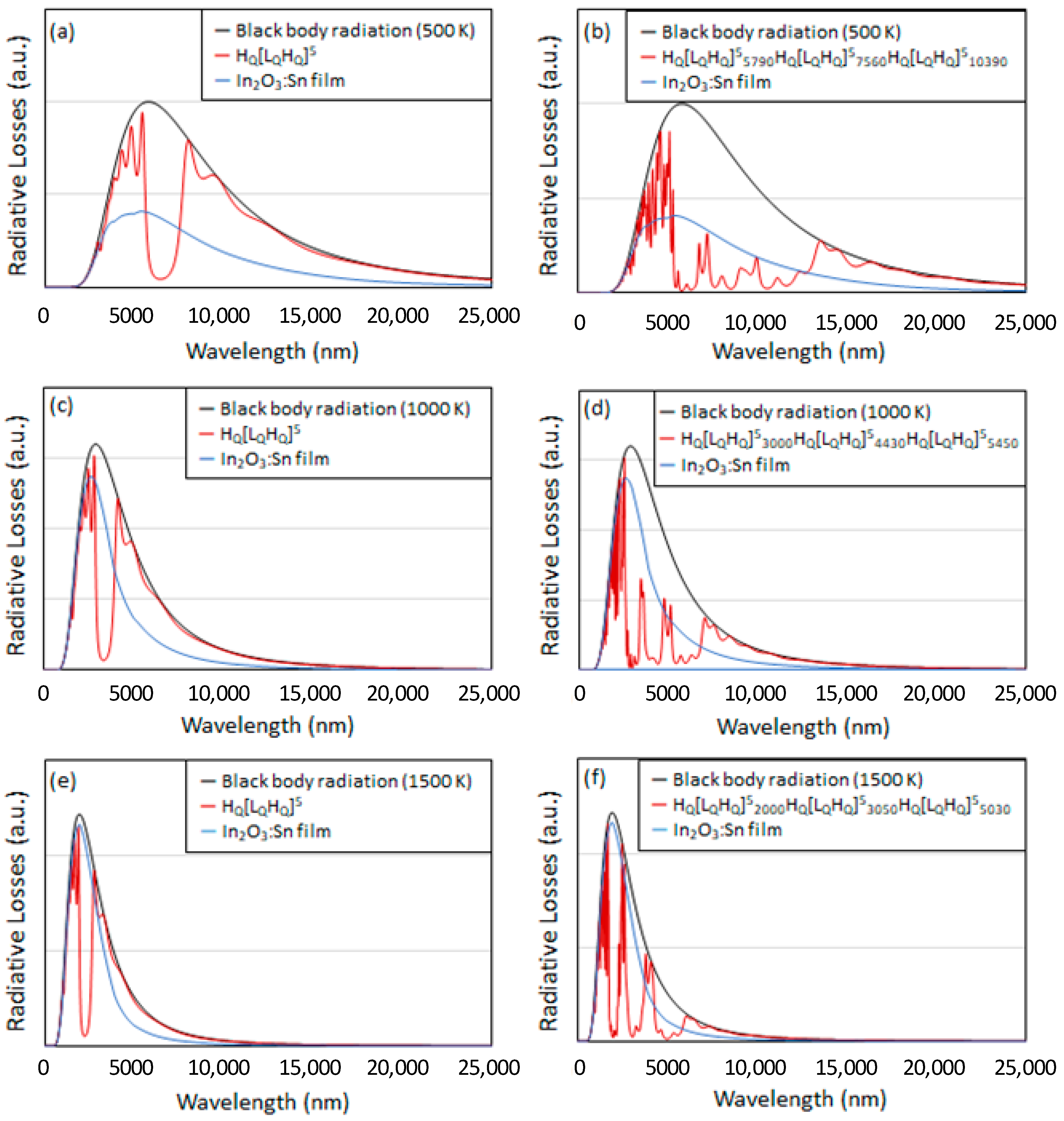
Figure 4 shows the radiative losses for receivers operating at 500 K, 1000 K, and 1500 K, that are covered with TCPHMs that have been optimized for these operating temperatures. The interfaces within the TCPHMs considered in
Figure 4 have a graded index of refraction with a quintic profile, which provide for the highest values of
t/
εeff considering the TPCHMs discussed with reference to
Figure 1. Moreover,
Figure 5 shows the percentage of the solar irradiance transmitted and thermal radiation reflected from TPCHMs covering receivers at operating temperatures of 500 K, 1000 K, and 1500 K. The percentage of the solar irradiance transmitted and thermal radiation reflected by a conventional transparent heat mirror, namely a 0.32 μm thick In
2O
3:Sn film deposited via e-beam evaporation, is also shown in
Figure 5 for comparison [
31]. Furthermore,
Figure 5a–c show the value of
t/
εeff when the blackbody receiver is at an operating temperature of 500 K, 1000 K, and 1500 K, respectively, for each receiver cover that was considered.
Figure 4a shows the spectral radiation losses from a receiver at 500 K covered with H
Q[L
QH
Q]
5. For comparison, the radiation losses for the case in which the receiver is covered with the In
2O
3:Sn reference film is also shown. The amount of radiation lost through the H
Q[L
QH
Q]
5 and In
2O
3:Sn covers is 73.1% and 38.5% for the H
Q[L
QH
Q]
5 and In
2O
3:Sn covers, respectively. The amount of radiation lost can be reduced to 37.3% by using a triple-stack configuration wherein H
Q[L
QH
Q]
55790·H
Q[L
QH
Q]
57560·H
Q[L
QH
Q]
510390 is used as the receiver cover, as shown in
Figure 4b. Thus, the triple-stack TPCHM offers just a slight advantage over the In
2O
3:Sn cover when the receiver is operating at a temperature of 500 K. As shown in
Figure 5a, the value of
t/
εeff for a black body receiver at 500 K is 2.19 when it is covered with the In
2O
3:Sn reference film, while
t/
εeff = 2.59 when the receiver is covered with H
Q[L
QH
Q]
55790·H
Q[L
QH
Q]
57560·H
Q[L
QH
Q]
510390. For all other TPCHMs that are considered in
Figure 5a (other than H
Q[L
QH
Q]
55790·H
Q[L
QH
Q]
57560·H
Q[L
QH
Q]
510390), the value of
t/
εeff is less than that for the case of the In
2O
3:Sn reference film.
The emission losses through H
Q[L
QH
Q]
55800 and H
Q[L
QH
Q]
53000·H
Q[L
QH
Q]
54430·H
Q[L
QH
Q]
55450, which are optimized for a receiver operating at 1000 K, are shown in
Figure 4c,d, respectively. Likewise, radiative losses through H
Q[L
QH
Q]
55800 and H
Q[L
QH
Q]
52000·H
Q[L
QH
Q]
53050·H
Q[L
QH
Q]
55030, optimized for a receiver operating temperature of 1500 K, are shown in
Figure 4e,f, respectively. As the operating temperature of the receiver increases its black body radiation spectra shifts to shorter wavelengths and, for high enough operating temperatures, begins to overlap with the incident solar radiation spectra. At these higher operating temperatures, the performance of conventional transparent heat mirrors, such as the In
2O
3:Sn reference film, decreases, because these films transmit a larger portion of the blackbody radiation emitted by the receiver. That is, conventional transparent heat mirrors do not exhibit a sharp cut-off and they transmit solar radiation, but are highly reflective towards radiation that is emitted from a receiver at temperatures of 1000 K or higher. On the other hand, the TPCHMs that are discussed in this work can be designed to simultaneously exhibit higher transmittance of solar radiation and reflectance of radiation from receivers operating at these higher temperatures. For example, H
Q[L
QH
Q]
53000·[L
QH
Q]
54430·[L
QH
Q]
55450 transmits 90.9% of the solar irradiance, as compared to 84.4% transmitted by the In
2O
3:Sn reference film, as shown in
Figure 5b. At the same time, H
Q[L
QH
Q]
53000·[L
QH
Q]
54430·[L
QH
Q]
55450 reflects 60.0% of the radiation from a receiver operating at 1000 K, while, in comparison, the In
2O
3:Sn reference film reflects just 40.4%. Also shown in
Figure 5b,
t/
εeff = 1.42 when the In
2O
3:Sn reference film is used as the cover for a receiver at 1000 K, and
t/
εeff increases to 2.27 when H
Q[L
QH
Q]
53000·[L
QH
Q]
54430·[L
QH
Q]
55450 is used as the cover.
The advantage of the TPCHM cover the In
2O
3:Sn reference film is more pronounced when the operating temperature is 1500 K. As shown in
Figure 5c, H
Q[L
QH
Q]
52000·[L
QH
Q]
53050·[L
QH
Q]
55030 and the In
2O
3:Sn reference film transmit approximately the same amount of solar radiation; 84.4% for the In
2O
3:Sn reference film as compared to 84.1% for H
Q[L
QH
Q]
52000·[L
QH
Q]
53050·[L
QH
Q]
55030. However, H
Q[L
QH
Q]
52000·[L
QH
Q]
53050·[L
QH
Q]
55030 reflects 57.6% of the radiation from the 1500 K receiver, while, in comparison, the In
2O
3:Sn reference film reflects just 25.7%. Furthermore, as shown in
Figure 5c,
t/
εeff = 1.14 when the In
2O
3:Sn reference film is used as the cover for a receiver at 1500 K, and
t/
εeff increases to 2.98 when H
Q[L
QH
Q]
53000·[L
QH
Q]
54430·[L
QH
Q]
55450 is used as the cover. Notably,
t/
εeff = 1.65 when H
Q[L
QH
Q]
52410[L
QH
Q]
53760 is used to cover a receiver operating at 1500 K.
The results that are presented herein show that using TPCHMs for the application of transparent heat mirrors can improve the performance by decreasing the effective emissivity at higher temperatures. However, fabricating these TPCHMs presents a challenge due to their number of layers and the level of precision that is needed to achieve the required refractive index profiles throughout the structure. While fabrication of thin-films with graded index profiles is challenging, a variety of methods for fabricating high-quality thin-films with a range of optical properties, including oblique angle deposition, plasma-enhanced chemical vapor deposition, and sol-gel processes exist and they are presently being developed for greater control over film properties [
32,
33,
34,
35,
36,
37,
38,
39]. Furthermore, recent research has been directed towards the development of transparent films with very low indices of refraction, such as mesoporous and aerogel films [
40,
41,
42,
43]. Future research will focus on using low-index films to reduce the number of layers required for fabricating the TPCHMs because the amount of thermal radiation they reflect increases with increasing contrast between their high- and low-index of refraction layers. Furthermore, the films modelled in this work are assumed to be non-absorbing, and the performance of the TPCHM decreases as the absorbance of their constituent layers increases. The materials that are selected for TPCHM fabrication should have low absorbance (e.g. k ~ 0.01) up to about 15 μm and 10 μm for receiver operating temperatures of 1000 K and 1500 K, respectively [
44]. Notably, doping is not required when fabricating films within the TPCHM, because high reflectance (or low effective emissivity) for thermal radiation is achieved through the macroscopic structuring of these dielectric mirrors, rather than by tuning their free electron concentration. Moreover, in practical applications, material dispersion must be taken into consideration, because achieving a low effective emissivity requires a high contrast in the index of refraction between the materials within the TPCHM over the broad spectral wavelength region over which reflection of thermal radiation is required. As can be noted from the width of the radiation spectra for black bodies at 500 K, 1000 K, and 1500 K, as in
Figure 4, the width of the spectral range over which high contrast is required decreases as the temperature of the receiver increases. On the other hand, high contrast between the constituent materials within the TPCHM is not required for achieving high solar transmittance.
Another important point to consider is the temperature that the TPCHMs will reach during operation. In this work it is assumed that the radiative losses from the TPCHM are small, because their temperature is assumed to be much lower than that of the receiver during operation. It is desirable for the TPCHM to be kept at low temperatures, not only to reduce thermal radiation losses, but also to avoid unwanted thermal effects, such as thermal expansion and degradation of the refractive index profile of the layers within the TPCHM. In practical solar thermal applications, low transparent heat mirror cover temperatures are readily achievable for the case of evacuated solar collectors, while it is challenging to maintain lower window temperatures in the design volumetric solar collectors.
As a more practical example, we also considered TPCHMs that were made from ZnSe and SiO
2 nanoparticle films. We performed numerical calculations to determine the solar transmittance, thermal reflectance, and the value of
t/
εeff for TPCHM covers working with a receiver operating at a temperature of 1500 K. The optical properties for ZnSe and SiO
2 up to a wavelength of 14 μm were attained from the literature [
45,
46,
47,
48]. The emission spectra from a blackbody at 1500 K peaks at ~1.9 μm and becomes negligible for wavelengths greater than 14 μm, as shown in
Figure 4e. The optical properties for SiO
2 nanoparticle films were estimated by taking a weighted average of the optical properties of air and solid SiO
2, where it was assumed that the composition of these films is 30% air and 70% SiO
2 by volume. For this example, ZnSe was selected, because it has a high refractive index over the infrared spectral region of interest (for example the index of refraction of ZnSe is ~2.4 over the spectral range extending from 2 μm to 14 μm). This relatively high index of refraction of ZnSe has good contrast in comparison to the index of refraction of the SiO
2 nanoparticle films, which have an index of refraction equal to 1.32 at 1.9 μm. The results from this analysis show that the optimum value of
t/
εeff occurs when the Bragg-reflectance peak position for TPCHMs comprised of ZnSe and SiO
2 nanoparticle films are at 1960 nm and 2086 nm in the case of interfacial step- and quintic-profiles, respectively. The solar transmittance for H[LH]
51960 and H
Q[L
QH
Q]
52086 are 65.2% and 75.6%, respectively. Furthermore, 40.3% and 37.4% of the thermal radiation emitted from a blackbody at 1500 K is reflected from H[LH]
51960 and H
Q[L
QH
Q]
52086, respectively. The values of
t/
εeff associated with H[LH]
51960 and H
Q[L
QH
Q]
52086 are 1.09 and 1.21, respectively, and, in comparison
t/
εeff = 1.14 for the In
2O
3:Sn reference film. Thus, for the case of a blackbody receiver operating at 1500 K, the In
2O
3:Sn reference film outperforms H[LH]
51960, while H
Q[L
QH
Q]
52086 exhibits the highest performance. In this example, H[LH]
51960 did not perform as well as the In
2O
3:Sn reference film, because it reflects a large amount of the incident solar radiation, which is caused by the relatively high index of refraction of ZnSe. However, the graded interfacial profiles within H
Q[L
QH
Q]
52086 decrease the reflectance of solar radiation, which allows for a significantly larger amount of solar radiation to be transmitted through the TPCHM and absorbed by the receiver. The improved solar transmittance due to the structure of H
Q[L
QH
Q]
52086 enables this TPCHM to outperform the In
2O
3:Sn reference film.


