1. Introduction
Interest in systems converting thermal energy into mechanical energy and especially Stirling technology derives from the increased demand for better management of heat obtained from other processes [
1,
2,
3]. In addition to the high thermal efficiency mentioned above, the Stirling design is characterized by a simple construction–no valvetrain, i.e., a small number of moving elements that can be a source of noise and vibrations, and no impact on the natural environment when the power supply is based on fuel coming from biomass, biogas, geothermal sources or solar energy [
3,
4,
5,
6]. An advantage of Stirling’s design is its simple construction in comparison with internal combustion engines [
7], as its parts, e.g., the piston crown, are not exposed to high temperature working gases and chemical impact because the energy conversion process takes place outside the combustion chamber [
8]. The foregoing advantages ensure maintenance-free operation and reliability.
Currently, as a result of growing interest in the use of renewable energy sources to generate electricity worldwide, a series of research on Stirling engines is being processed [
9,
10,
11,
12]. Cheng et al. [
13] developed and tested a beta type Stirling engine with a rhombic-drive mechanism (displacer diameter: 70 mm, displacer swept volume: 135 c.c.). The experiments were conducted for two different working gases (air and helium) and at various charge pressures and heating temperatures. For helium, as the working gas, at a charge pressure of 8 bar and heating temperature of 850 °C, the shaft power of the engine can reach 390 W at 1400 rpm with 1.21 kW input heat transfer rate (32.2% thermal efficiency). For air as the working gas at a charge pressure of 6 bar and a heating temperature of 650 °C, the shaft power of the engine can reach 60 W at 700 rpm.
Gheith et al. [
14] tested a gamma type Stirling engine with air as the working gas (displacer diameter 95 mm, displacer swept volume: 850 c.c.). A maximum brake power of 355 W was obtained for a charge pressure of 8 bar and a heating temperature of 500 °C at 600 rpm. On the basis of tests and calculations performed for the heating temperature of 300 °C the expected brake power is 150 W.
Karabulut et al. [
15] designed and manufactured a beta type Stirling engine (displacer diameter: 69 mm, displacer swept volume: 295 c.c.) which works at relatively lower temperatures. The presented experimental results were obtained by testing the engine with air as the working gas. The hot end of the displacer cylinder was heated with an LPG flame and maintained about 200 °C. The maximum power output obtained at 2.8 bars charge pressure was 52 W at 453 rpm. The thermal efficiency corresponding to the maximum power was determined as 15%.
Kongtragool et al. [
16] designed and constructed four power pistons, gamma type, low temperature, differential Stirling engine (displacer diameter: 32 mm, displacer swept volume: 6394 c.c.). The engine performance was tested with air at an atmospheric pressure by using a gas burner as a heat source and a heating temperature of 498 °C. The engine produces the maximum shaft power of 32.7W at 42.1 rpm and a maximum brake thermal efficiency of 0.81%.
Li et al. [
17] developed a beta type Stirling engine with an output shaft power of several kilowatts, which could be driven by mid-high temperature waste gases (displacer diameter: 102 mm, displacer swept volume: 462 c.c.). The engine performance was tested with helium at a charge pressure of 20 bar and a heating temperature of app. 500 °C. The maximum power output obtained was 3476 W at 1248 rpm. The thermal efficiency corresponding to maximum power was determined as 26%.
Sripakagorn et al. [
18] developed a beta type Stirling engine (displacer diameter: 74 mm, displacer swept volume: 165 c.c.). The engine performance was tested with air as the working gas at a charge pressure of 7 bar and a heating temperature of 500 °C. The shaft power of the engine can reach 95 W at 360 rpm (9.35% thermal efficiency). Under the atmospheric pressure, the engine produces a maximum power of 3.8 W at 205 rpm and 350 °C.
A free piston (beta type) Stirling engine was invented by Lane and Beale [
12] (displacer diameter: 0.044 m, displacer stroke: 0.04 m). The stable engine operation was obtained at the temperature range of 120–150°C at the heater section (initial gas pressure: 101 kPa). The maximum efficiency of 5.6% at 6.4Hz of frequency was obtained.
Qian et al [
19] carried out tests on a beta type Stirling engine powered by a mixture of fuels: poultry litter and natural gas, showing that it is possible to use moderate temperature heat sources (cylinder head temperature: 220–584 °C) in a commercial engine, which was designed for high temperatures heat sources. In addition, it was shown that there is a noticeable influence of the water flow rate supplying cooling system on electrical power produced by the Stirling engine. The cooling water flow rate affected indirectly the temperature of the lower heat source as well as the temperatures of block and cylinder head.
Sowale et al. [
20] performed an analysis of the thermodynamic performance of a gamma type Stirling engine integrated into a micro combustor. An analysis was performed using an adiabatic model for a moderate temperature level of the heat source (150–390 °C), while the engine achieved a power greater than zero at 328 °C. The analysis showed that for a heating temperature of 390 °C, the Stirling engine produced the highest power of 27 W, at the thermal efficiency of 18%.
Tlili et al. [
21] presented a concept of an alpha type Stirling engine powered by a solar dish, which can be supplied by the moderate temperature source of heat (320 °C). Performed analysis concerned the influence of a dead volume on the rated power. The optimal dead volume of 370 cm
3 was calculated, which corresponded to the operating frequency of 75 Hz and the power of 250 W.
Stirling engines available commercially on the market are usually sold as combined heat and power units fuelled by natural gas or diesel fuel. An example of a cogeneration unit which can be supplied with energy from renewable sources, is a unit from StirlingDK (Lyngby, Denmark). The system consists of an expanded combustion chamber, a four-cylinder, two-sided alpha type Stirling engine and an electric generator enclosed in a sealed housing. This arrangement enables the engine to be supplied with the thermal energy derived from burning wood waste in the form of chips. An operational electrical efficiency of 28% is achieved at a power output of 30 kW. For the correct operation of the device the burning gas temperature, in the combustion chamber, should not be lower than 1000 °C.
Another example of a commercial cogeneration unit with a Stirling engine that can be supplied with energy from renewable sources, is a unit from Stirling Biopower (Ann Arbor, MI, USA). This arrangement also consists of a four cylinder, two-sided alpha type Stirling engine and an electric generator enclosed in a sealed housing. The combustion of the biomass takes place in a separate unit that heats the air supplied to the heater. For the correct operation of the device the temperature of the air supplied to the heater should not be lower than 500 °C. The system is also equipped with an integrated combustion chamber, supplying flue gases to the heater. The integrated chamber can be supplied with the following gases: CNG, LPG, biogas, synthetic gas and hydrogen. Operating with gaseous fuels of energy densities 13 MJ/Nm3 and higher, the electrical efficiency of 29% at 38 kW can be achieved.
To conclude, powering a Stirling engine with renewable energy or waste heat can be efficiently applied when the heat exchange surface of the heater is significantly increased, to cover energy demand for much lower temperature (moderate) of the energy source. This solution in turn, causes an increase of the dead volume, which contributes to the reduction of the thermal efficiency of the device.
Taking these restrictions into consideration, a prototype alpha type Stirling engine has been constructed. The heater has been designed to be supplied with exhaust gas from another process at a moderate temperature. A series of tests have been performed on the prototype engine, which unfortunately indicated that the power produced by the engine is lower than the mechanical resistance in the crankshaft system. The tests have been conducted using an external source of mechanical power, which covered the difference between the mechanical resistance and the indicated power. The obtained results enabled calibration of the theoretical model of the Stirling engine, which has been used for the analysis of regenerator effectiveness influenced by the charge pressure and the temperature of the heat source. Performed study allowed to determine further development directions of the prototype engine to improve its power and efficiency.
3. Experimental Setup and Test Procedure
The tests were carried out at the rotational speed of 550 rpm using an electric motor. The temperature of the exhaust gas entering and exiting the heater, as well as temperature of the cooling water, have been measured using type K thermocouples. The charged air is provided to the engine via a compressor with a pressure regulator. The pressure of the working gas in the Stirling engine has been measured using an NPXTG 10 sensor (Peltron, Wiazowna, Poland). The position of the crankshaft, as well as rotational speed has been measured using a position sensor. The position of the crankshaft between markers has been interpolated basing on temporary rotational speed. Data have been recorded at a frequency of 10 kHz using data logger. The measurement uncertainty of apparatus used in the tests has been presented in
Table 2.
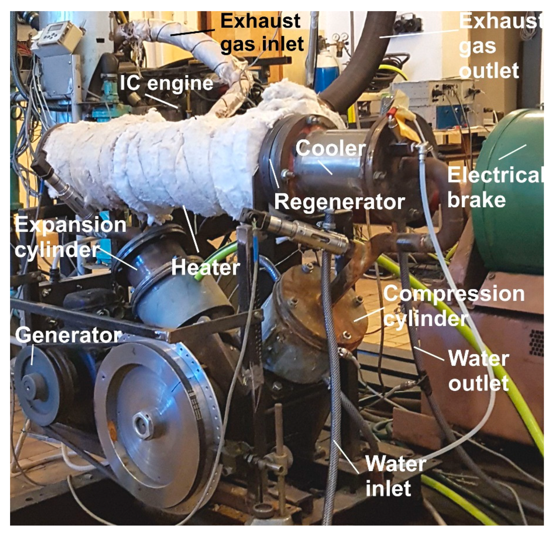
The tests began with warming up the exhaust gas supplying the heater to the assumed temperature, then the pressure of the working medium was changed to the required value using a compressor, finally operating conditions were recorded. Temperature and flow rate of the exhaust gas have been controlled by operating point (speed, torque) of the internal combustion (IC) engine, using an electrical brake connected to the IC engine (
Figure 2). Regulation of the IC engine took place by means of exhaust gas temperature, which then flowed to the heater of the Stirling engine. Regulation of the IC engine was not influenced by the Stirling engine operating parameters. Achieved accuracy of the exhaust gas temperature regulation (inlet of the heater) is ± 1 °C. The exhaust gas flow rate suppling the heater was calculated on the basis of the fuel consumption of the internal combustion engine and the excess air ratio. The water flow rate in the cooler has been kept constant (
Table 1). The rising thermal load of the Stirling engine causes more intensive transport of the heat from the heater to the cooler via working gas, as a result temperature of water at the outflow of the cooler is also rising.
The indicated work of the engine has been calculated on the basis of the pressure course in the working space using the following formula:
where p
seni is pressure of the working gas measured by the sensor, ΔV
ei is change of volume in the expansion cylinder, ΔV
ci is change of volume in the compression cylinder and i
max is the number of samples (360 for assumed resolution 1 sample per 1 crankshaft rotation degree).
The change of volume in the compression and the expansion cylinder was determined on the basis of the system design features and the measurement of the instantaneous position of the crankshaft using the position sensor. The indicated power can be calculated using rotational speed of the crankshaft:
where n indicates the rotational speed of the crankshaft measured by the position sensor.
4. Engine Performance
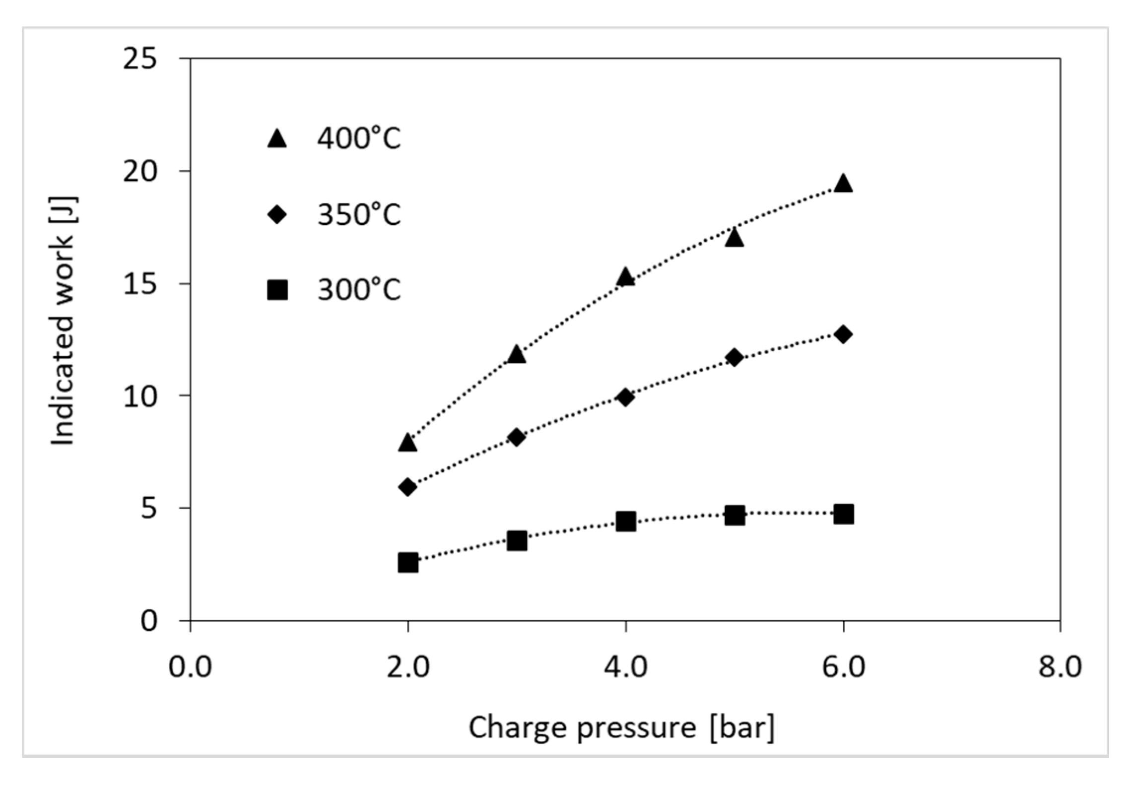
The performed tests have been completed using air as a working gas. The prototype Stirling engine has been charged with compressed air ranging from 2 to 6 bar absolute pressure. Three levels of temperature of thermal energy source (exhaust gas from spark ignition engine) have been tested: 300, 350, 400 °C. Recorded pressure of working gas and position of the crankshaft allowed to calculate indicated work and power of the engine. This result does not include mechanical resistance of the crankshaft system which has the crucial influence on the performance of the engine. In
Figure 3 and
Figure 4, the indicated work and power have been presented subsequently. It can been observed that depending on temperature of the thermal energy source, the optimum charge pressure is changing from 2 bar for 300 °C up to maximum tested level (6 bar) for 400 °C. It can be concluded that further rise of charge pressure should simultaneously increase the indicated work produced by the engine for 350 as well as 400 °C. Unfortunately, the sealing system used in the prototype engine is not suitable for such a level of pressure. The increase of the indicated work, due to heating temperature rise, is in line with the theoretical description of a Stirling engine cycle [
22,
23,
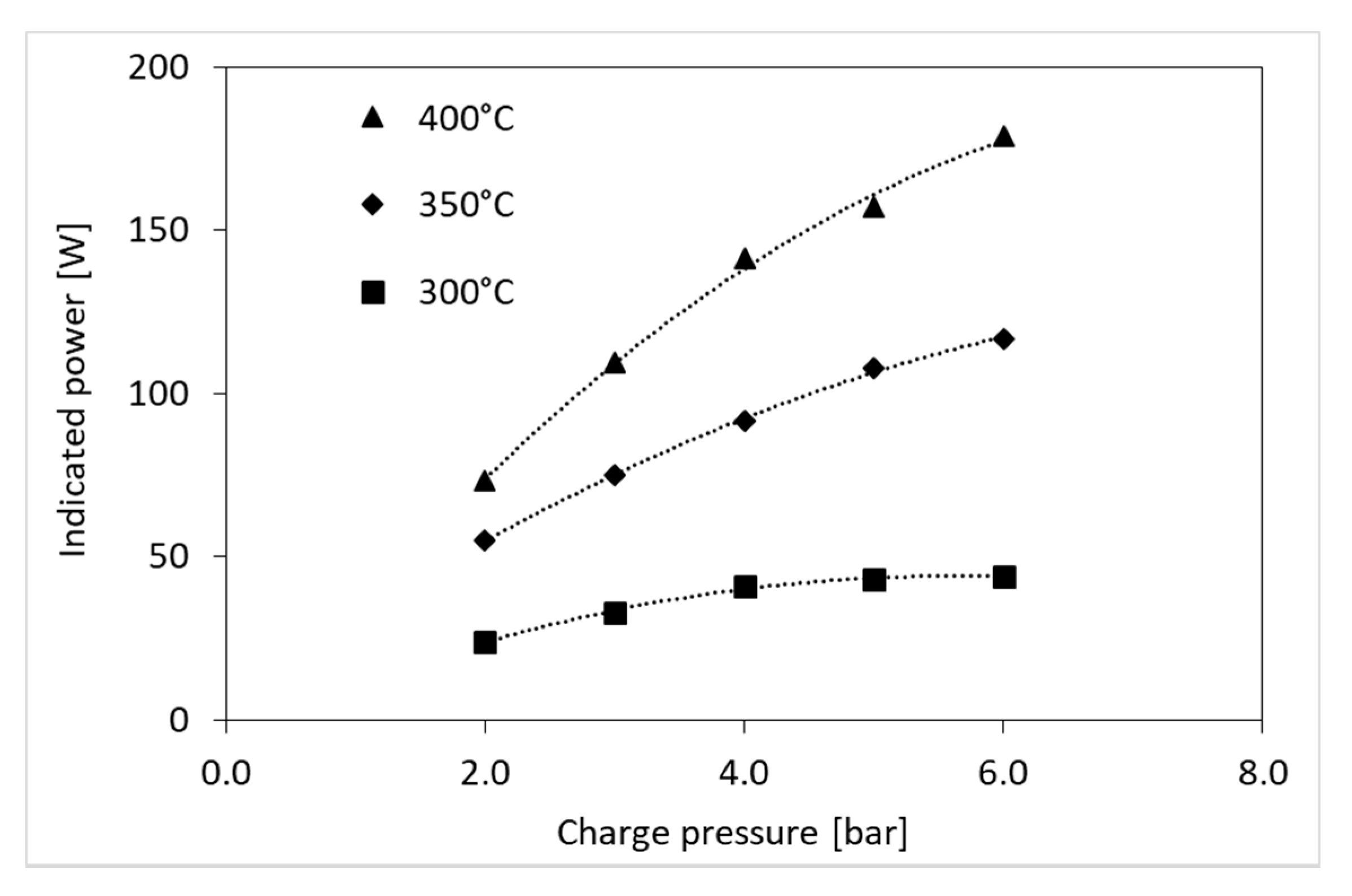
24], the higher temperature difference between upper and lower heat source, the higher efficiency of the engine, which means more work for the given thermal energy impact. The effect of rising efficiency is, at the same time, amplified by the increase of thermal energy transmitted by the heater to the working gas, which comes also from the higher heating temperature. The increase of the charge pressure, on the other hand, brings a proportional increase of the mass of the working gas, which performs the work. It can be stated that the increase of the charge pressure yields a similar effect to the increase of the swept capacity. In each of the discussed situations, the increase of the indicated power is proportional to the increase of the indicated work according to the relationship (2).
During the tests, it turned out that the power of the mechanical resistance of the device exceeds the power indicated in the Stirling engine and the engine is not able to work independently. The maximum indicated power of the engine is 180 W (
Figure 4), while the mechanical resistance for this operating point was estimated at 203 W. To start the engine autonomously, it is necessary to increase the indicated power or significantly reduce resistance, what has already been achieved by changing the sealing and lubrication system.
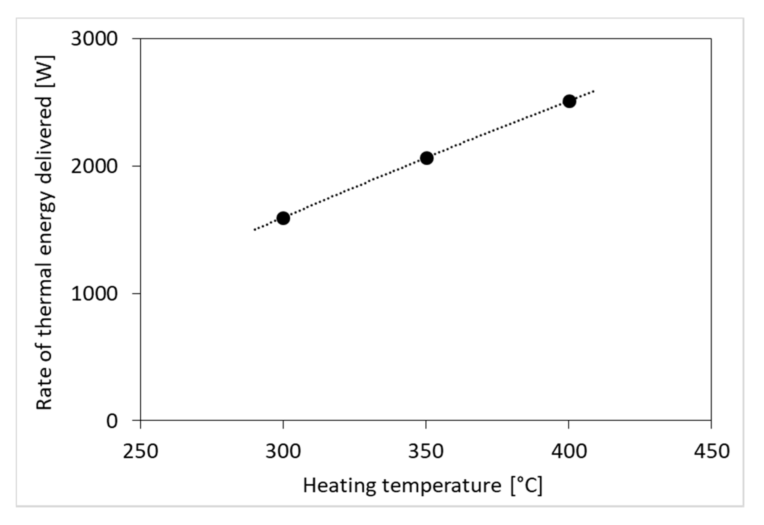
In
Figure 5, the rate of thermal energy delivered to the engine has been analysed. For each assumed temperature of thermal energy source the delivered energy rate is constant despite the changing Stirling engine charge pressure. The change of rate of delivered thermal energy follows approximately linearly the change of temperature. It should be mentioned that the thermal energy is delivered by internal combustion engine and the increase in rate of thermal energy resulted from both the increase in temperature and the mass flow rate of the exhaust gas, which practically meant an increase in the torque of the internal combustion engine driving the brake.
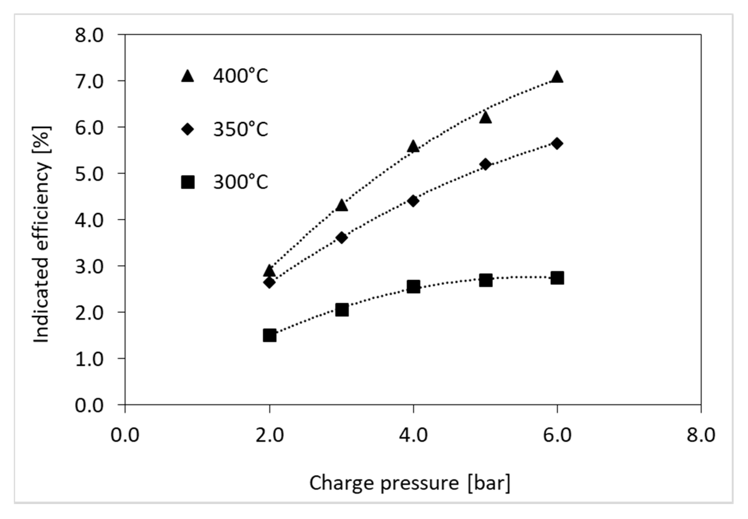
Obtained indicated efficiency of the Stirling engine has been shown in
Figure 6. Like in the case of the analysed indicated work, depending on temperature of the thermal energy source, the optimum charge pressure is changing from 5 bar for 300 °C up to maximum tested level (6 bar) for 400 °C. It can be concluded that further rise of charge pressure should simultaneously rise up the indicated efficiency produced by the engine for 350 as well as 400 °C.
The relatively low indicated efficiency obtained by the prototype engine is related to the low level of applied temperatures and high hydraulic resistance [
25], occurring in all working elements. In addition, the construction of the heater and cooler adds a relatively large dead volume to the working space of the engine. The total ratio of dead space to the swept volume is now 2.5 and should be lowered significantly to increase the engine efficiency. For this purpose, it is necessary to increase the number of tubes in the heat exchangers and reduce the internal diameter of the tubes.
In order to optimize the presented structure of the engine, due to the achieved efficiency, the theoretical model of the engine was developed for the assumed moderate level of temperatures. The model has been calibrated on the basis of experimental results presented in this section. The description of the theoretical model used in the research is given in the next section.
5. Theoretical Model of the Stirling Engine
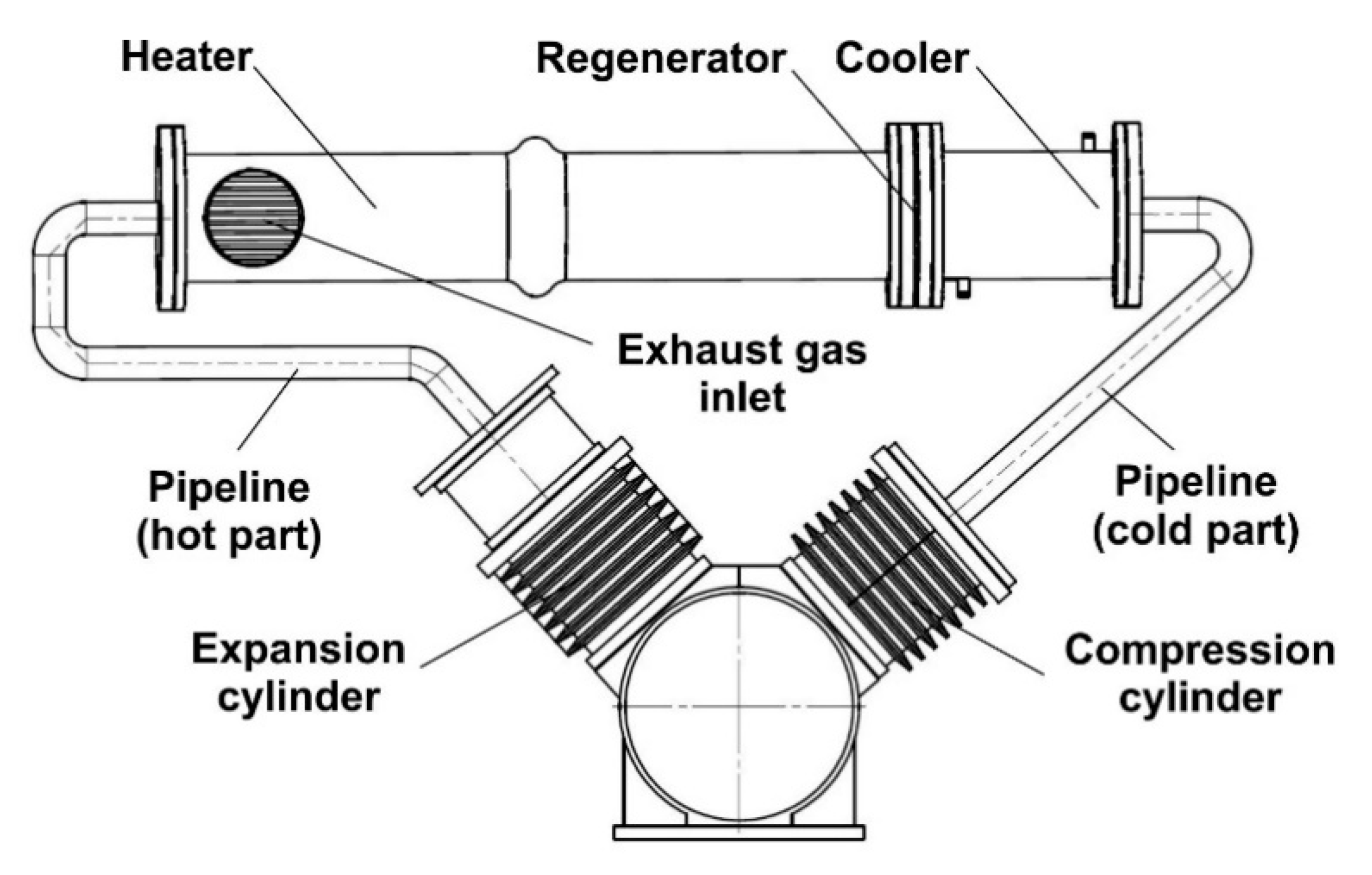
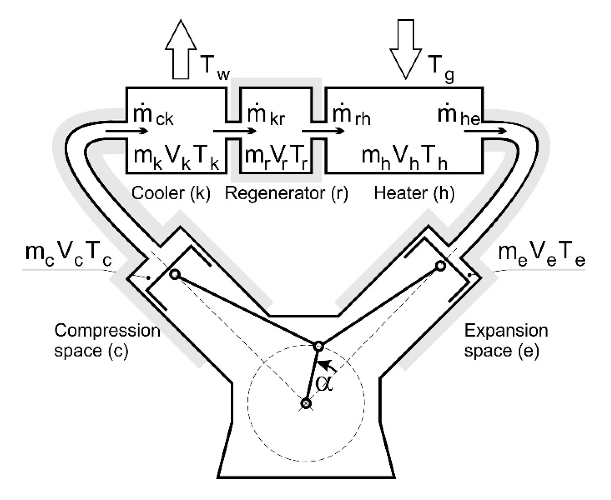
The alpha type Stirling engine (
Figure 7) is composed of two cylinders (expansion space E and compression space C), the regenerator that forms the space between the cylinders and the buffer space (under the pistons) [
8]. Heat from an energy source is supplied to the expansion space via heat exchanger [
26,
27,
28], whereas the heat from the compression space is removed at a lower temperature than the heat supplied to the expansion space. There is working gas in the working space and in the buffer space.
The theoretical Stirling cycle is a highly idealized thermodynamic cycle [
22,
29], therefore, its use is not recommended for quantitative analyses [
20,
30]. For practical analyses, the isothermal or adiabatic model [
23,
31,
32,
33,
34] is most often used, which allows the functional separation of engine working spaces into: compression space, cooler, regenerator, heater and expansion space. Unfortunately. Basing on the fundamental assumptions for the isothermal model the temperature of the gas in compression and expansion space is constant (as well as in each distinguished space). This implies that those exchangers are useless and the whole heat exchange process takes place in the compression and expansion space only. Obviously, this cannot be correct, since the cylinder walls are not able to cover the expected heat demand. The analysis was conducted using adiabatic model with the assumption that there is no heat exchange with environment in: the compression space, the regenerator, the expansion space and in adjacent pipelines.
The starting point of the analysis is that the instantaneous pressure in each element of the Stirling engine is the same for the pointed crankshaft position. The total mass of gas in the machine is constant, thus:
where
defines mass accumulation speed of the working gas in the space x (index x specification in
Figure 7).
Assuming that the conditions
and
are met for the heat exchanger we obtain for the cooler:
Similarly, for the regenerator and the heater we obtain respectively:
The pressure of the working gas can be calculated using the following formula:
For the compression space the temperature can be evaluated using the formula:
where:
Analogously, for the expansion space we obtain:
where:
The mass flows used in earlier equations can be defined using the following relations:
where:
In the regenerator, the gas cyclically flows from the cooler to the heater and in reverse direction. The gas is respectively heated and cooled by the metal mesh placed in the regenerator. The net heat transfer per cycle is zero. The regenerator quality is defined by the regenerator effectiveness
, the parameter that allows to calculate the regenerator temperature difference:
Hence, the temperature of the gas coming into the cooler from the regenerator will be higher than the temperature of gas in the cooler by 2εTr. Analogically, the gas coming into the heater from the regenerator will be cooler than temperature of gas in the heater by 2εTr.
The adiabatic work produced by the Stirling engine in the expansion and compression spaces for the whole cycle equals:
The working fluid is passing heat exchangers between compression and expansion cylinders accompanied by the friction and local loss, which results in a pressure loss across all the elements. This effect reduces the net work of the engine. In this work, the total pressure loss in a system has been treated as coming from the local losses, which allowed to define the instantaneous pressure loss:
where K
L is the loss coefficient,
is the working gas density in the pipeline (
Figure 1) and w is the instantaneous working gas velocity in the pipeline (
Figure 1).
Based on the tests [
25] performed for the analysed elements: cold pipeline, cooler, regenerator, heater, hot pipeline, the following relation has been evaluated:
where Re is Reynolds number for the pipeline (
Figure 1).
The pumping loss for one cycle can be then calculated as follows:
The net adiabatic work corresponding to indicated work, is a difference of the work calculated for the evaluated pressure change (19) and the pumping loss (22):
The energy delivered to the engine is given by:
The energy loss during cooling is given by:
The net adiabatic efficiency of the Stirling engine can be calculated using the following formula:
For a more realistic analysis it is convenient to define the temperature of the gas delivering heat to the Stirling engine (the waste energy) and the temperature of water receiving heat from the device instead of the temperature of working gas in the heater and the cooler, respectively [
35,
36]. Hence, assuming the energy is transferred with 100% efficiency through the heat exchanger, we can define the average rate of heat delivered to the working gas in the heater:
and the average rate of heat received from the working gas in the cooler:
The equations presented in this section are used to determine the desired parameters of the working gas, e.g., pressure, temperature in the compression space, expansion, engine efficiency, etc. Some of the variables contained in the equations can be assumed, for example, the volume of the compression space:
and for the expansion space:
Other variables depend on the direction of mass flow. Hence, the temperature of the working gas coming into the cooler from the compression space can be defined using the following formula:
Analogously, for the temperature of the working gas coming into the regenerator from the cooler we obtain:
and for the temperature of the working gas coming into the heater from the regenerator we obtain:
while for the temperature of the working gas coming into the expansion space from the heater we obtain:
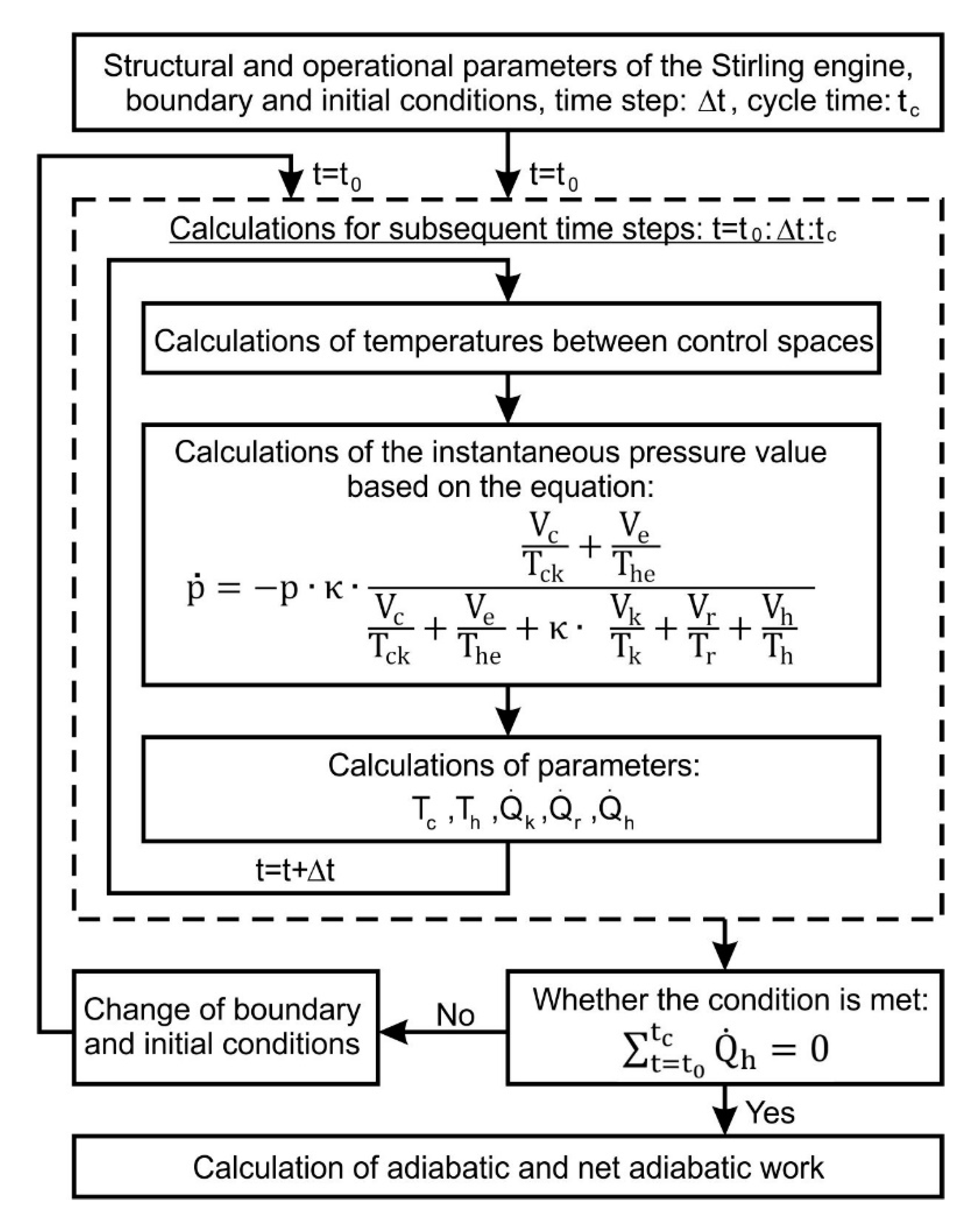
If the initial values of variables are not known, e.g., pressure, the temperature in the compression and expansion space, etc. we need to use iterative procedure for calculations (
Figure 8). In such a procedure, we assume that the cycle is of a repetitive nature, which means that the calculations can be completed when respective values at the beginning and the end of the cycle are the same, e.g., the temperature of the working gas in the compression space. Hence, the results of the calculations for one cycle of work are used as initial conditions in the next iteration. In the iterative procedure, the initial pressure and temperature values in all control volumes are assumed, as well as the temperature of the exhaust gas supplying heat to the engine and the temperature of the cooling water. In the first calculation step, the direction of the working gas flow in the Stirling engine is determined on the basis of the volume change balance in the expansion and compression space, hence the initial values of the gas stream and its temperature between control volumes are calculated. In the next steps, only the results from the previous calculation steps are taken into account. After each calculation step, the indicated work is calculated alongside with the amount of heat supplied, removed and accumulated by the regenerator. The convergence was controlled by the conformity of the compression and expansion temperatures at the end of one cycle and the beginning of the next one, as well as by the energy balance released and absorbed in the regenerator, which should equal zero.
6. Results and Discussion
On the basis of the test results of the Stirling engine prototype, the model was calibrated, taking as its input the prototype’s geometric and design features, charge pressure, heating temperature, cooling water temperature, heat transfer coefficients for the heater and cooler, as well as the loss coefficient function (21), which defines pumping loss.
The calibration has been performed assuming that the average value of the indicated work, for the considered operating points, cannot differ for model and experimental data by more than 1%.
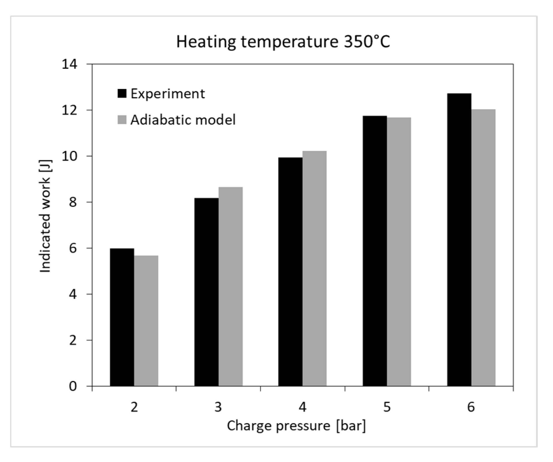
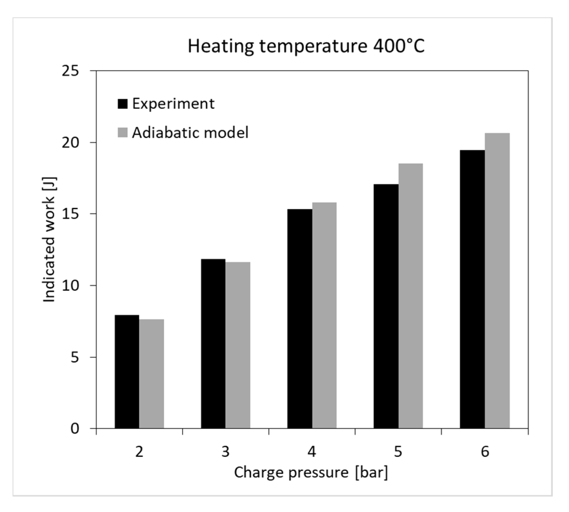
Figure 9,
Figure 10 and
Figure 11 present the results of comparison of the indicated work obtained from the experiment and the adiabatic model (pumping loss included). As a result of the calibration, regenerator effectiveness characteristics has been obtained, which was the last missing data in the model. Due to the high uniqueness of the regenerator designs used in prototype solutions [
24,
37,
38], this is a much more accurate method of determining its characteristics than the use of experimental formulas worked out for similar constructions.
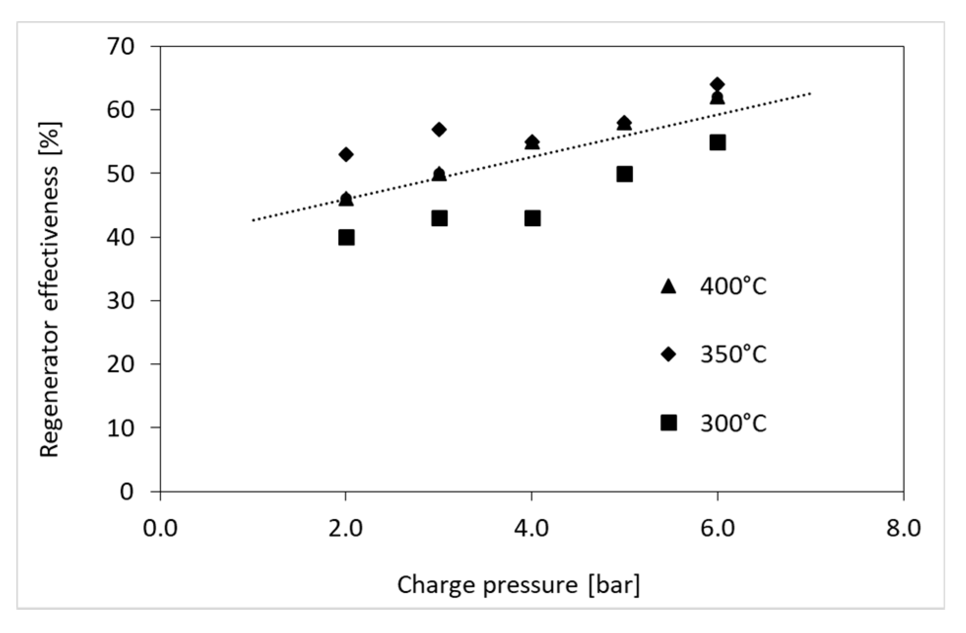
Figure 12 shows the regenerator effectiveness characteristics evaluated during the model calibration. Based on the obtained results, it can be concluded that in the tested temperature range the regenerator effectiveness is not explicitly related to this parameter. In the pressure range above 4 bar it can be seen that the increase in temperature also increases the efficiency but for pressures below 3 bar the regenerator effectiveness is higher at a temperature of 350 °C rather than 400 °C. Similar results were obtained in [
37], where also the general tendency of the regenerator effectiveness rise due to temperature is not always maintained and these changes occur in a similar range (±5% change in efficiency for temperature changes by 100 °C). In the case of rising charge pressure, a general tendency to increase regenerator effectiveness was observed, regardless of the heating temperature. In the work [
37] a similar pattern was found.
For further considerations regarding the impact of selected design features of the system on the efficiency and power, the authors decided to use the simplified characteristics of the regenerator effectiveness taking into account only the effect of charge pressure:
Using the calibrated adiabatic model of the Stirling prototype engine, the effect of dead heater and radiator volume on the efficiency and the power of the prototype engine was determined.
It was assumed that main structural features of the analysed engine were retained (
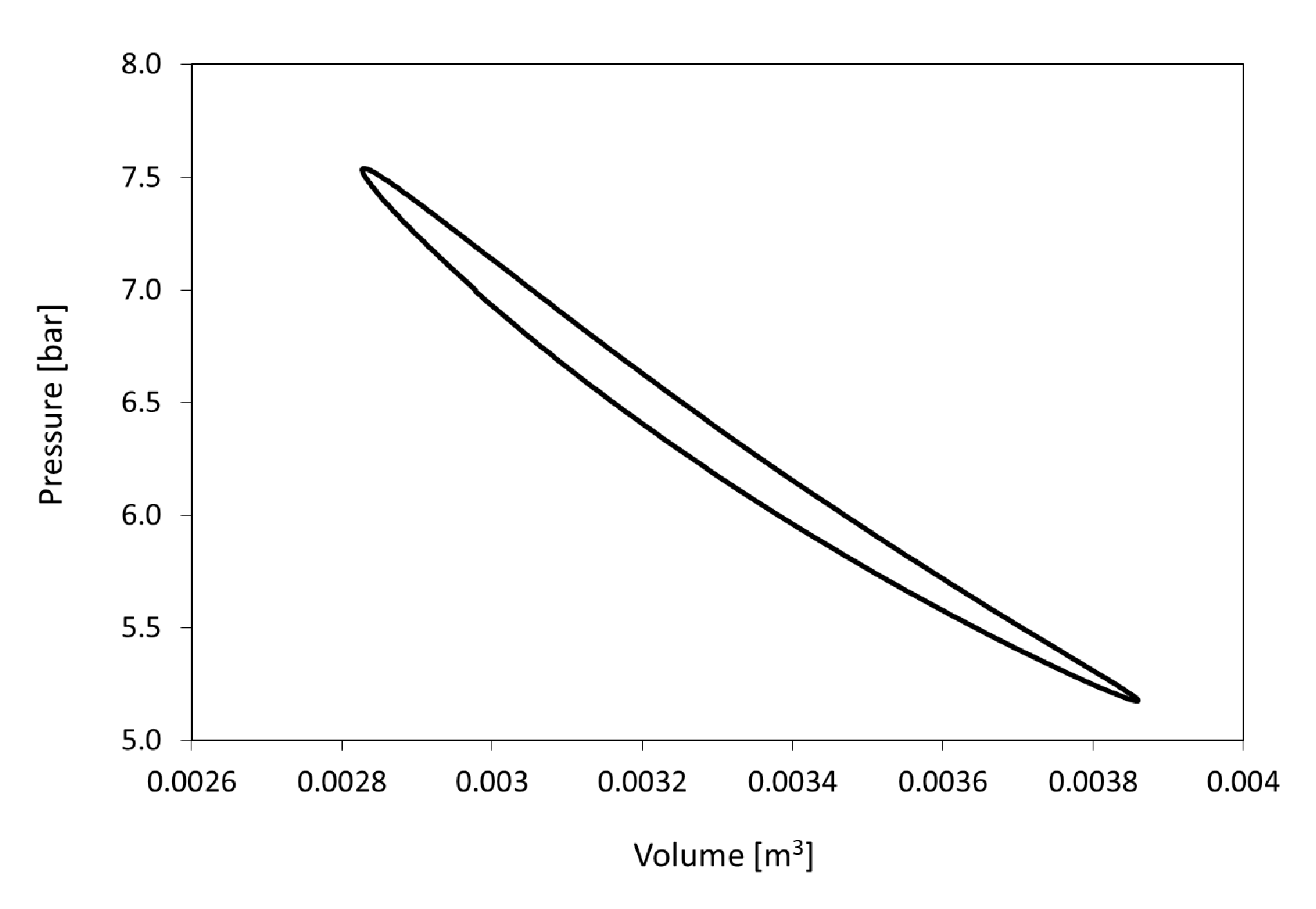
Table 1), only the dimensions of the heater and cooler (heat exchange surface and volume occupied by the working gas) were changed. For the original prototype engine configuration, at the heating temperature of 350 °C and the charge pressure of 6 bar, calculations of the temperatures in the selected spaces of the engine have been performed (
Figure 13 and
Figure 14), as well as the calculations of the pressure of the working gas (
Figure 15).
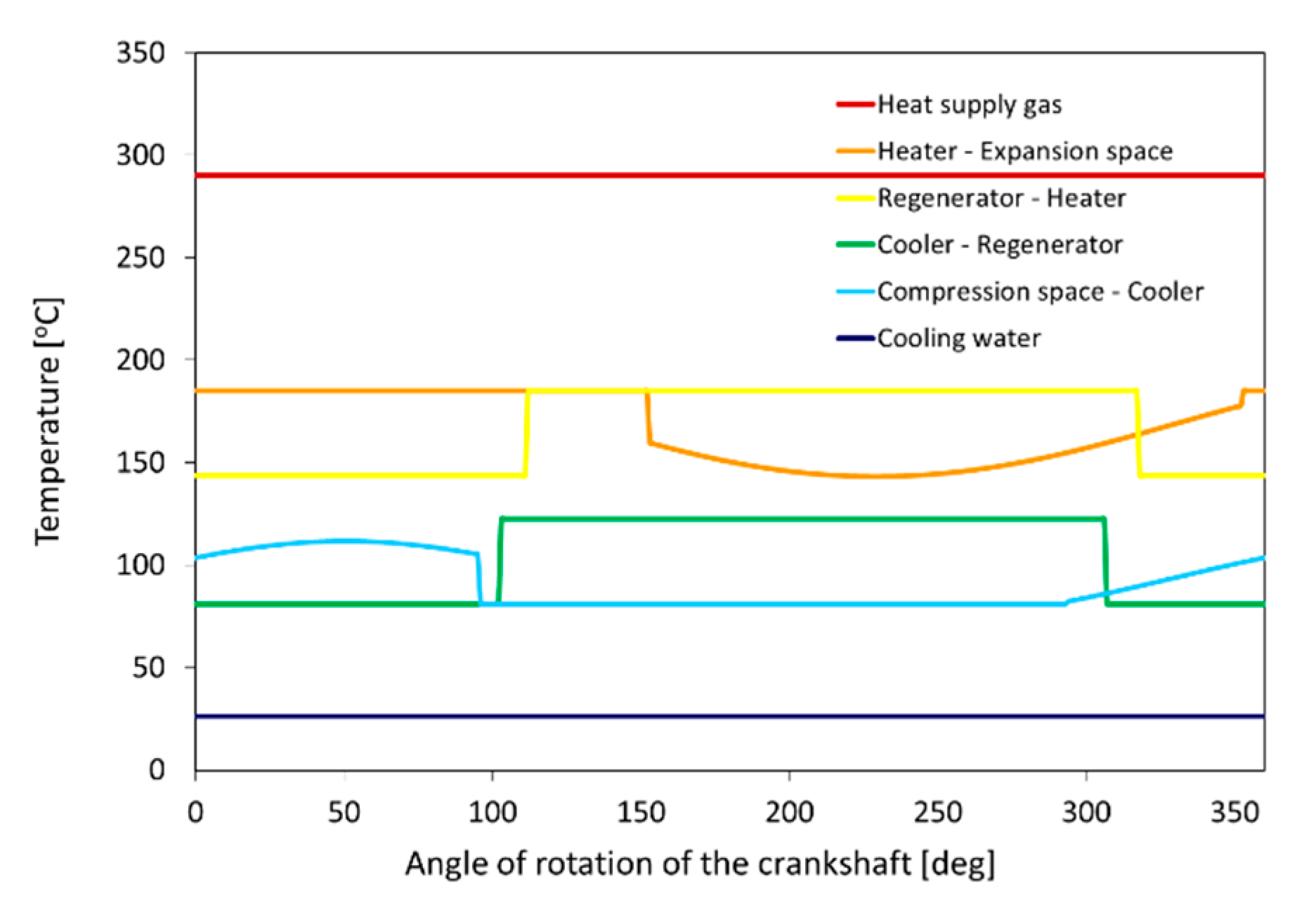
According to the assumptions of the adiabatic model, temperatures in heater, regenerator and cooler are constant, while in elements where the process is adiabatic i.e., expansion and compression space, the course of temperature has a sinusoidal profile (
Figure 13). However, at the boundaries of the control spaces, depending on the instantaneous flow direction, a rapid temperature change occurs (
Figure 14). For example, between the heater - expansion spaces, during the flow from the expansion space the temperature is lower, and during the flow from the heater, the temperature is higher and corresponds to that in the heater. On this basis, the adiabatic work has been calculated (19) and, after taking pumping loss (22) into account the net adiabatic work (23) has been also calculated.
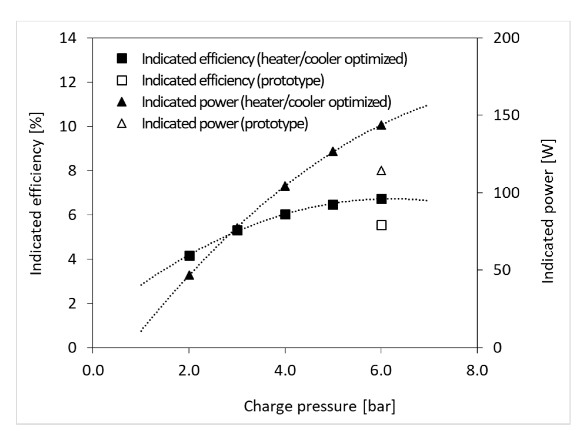
Next, the numerical optimization of the heat exchange surface in the heater and cooler has been performed due to charge pressure (
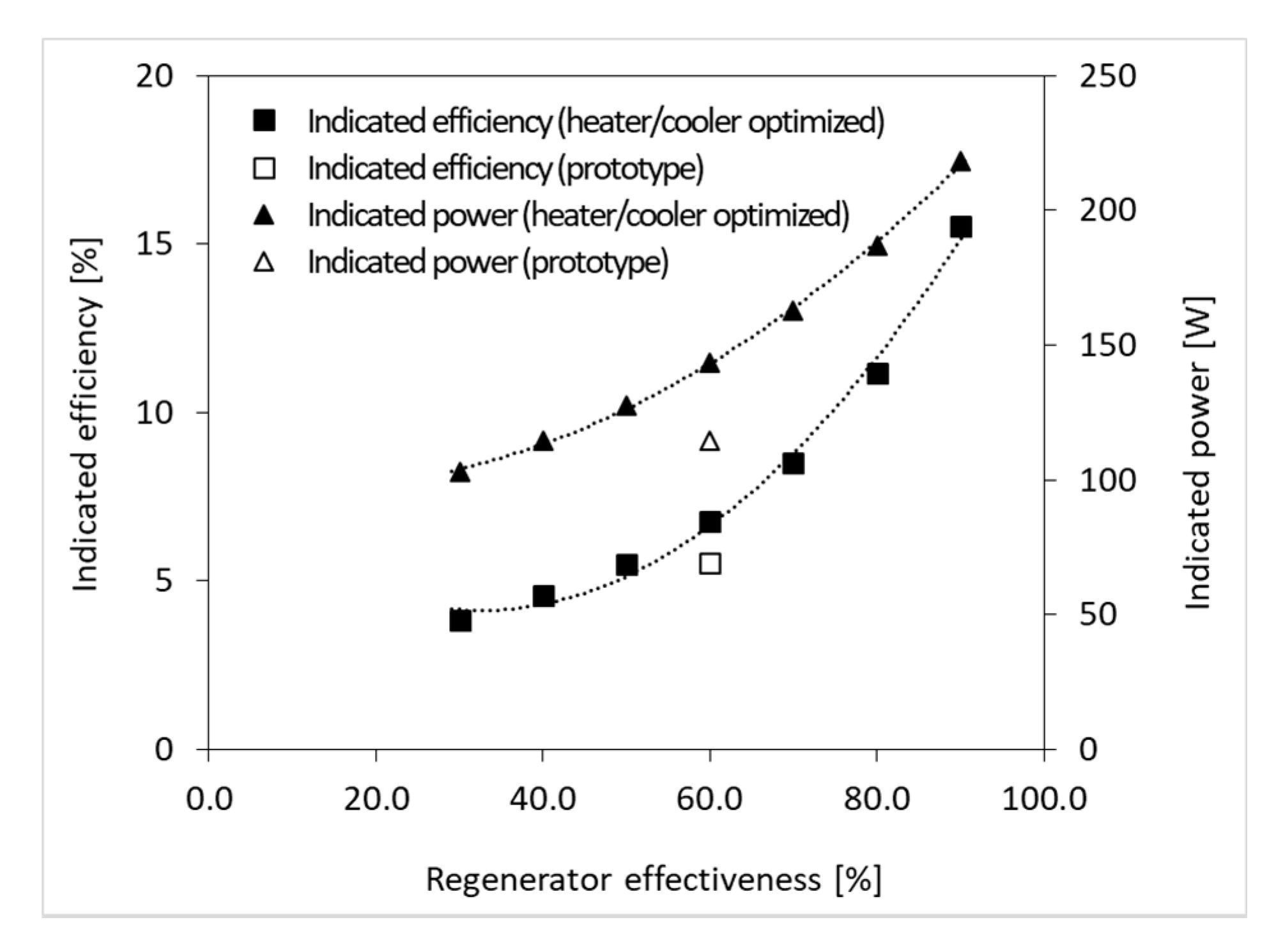
Figure 16) and regenerator effectiveness (
Figure 17). The changing the heat exchange surface resulted in a proportional change in the dead volume in the space of the heater and cooler. The simulations have been carried out for the heating temperature of 350 °C.
On the basis of the results (
Figure 16), it can be stated that the engine power increases along with the charge pressure, which is caused by the increase in the amount of the gas performing the work. However, this is not accompanied by a significant increase in the flow velocity, which is associated with hydraulic resistance. The engine efficiency reaches approximately the maximum value also at 6 bar pressure, while further increase is limited due to the imperfection of the adiabatic model describing the process. In this model, it is assumed that the temperature in the heater and cooler is constant, which means that it is necessary to bring or remove huge amounts of heat, when the expansion or the compression is underway in the working space. Further increase of the charge pressure, therefore, causes a proportional increase in the mass of the working gas, and in the consequence of the model’s operation, an increased amount of heat input and increased dimensions of heat exchangers and the dead space. Especially the last factor has a negative impact on the engine efficiency. The impact of charge pressure on engine efficiency is not determined by the adiabatic model in a sufficiently accurate manner and requires refinement. In a real engine, the processes of heat supply and dissipation are not isothermal and this disruption needs to be corrected by refining the Stirling engine model allowing non-isothermal way of these processes.
Based on the results presented in
Figure 17 it can be concluded that engine power and efficiency increase relatively quickly with regenerator effectiveness. This is the result of an increasing amount of heat that is delivered from the regenerator during the expansion process, and thus a reduction of the amount of heat that must be supplied from the outside.
The results presented in
Figure 16 and
Figure 17 both show that it is possible to significantly increase the efficiency and power of the engine by optimizing the heat exchange surface of the heater and cooler. The result of this process, however, depends on the operating parameters of the engine, so it must be repeated when the heating temperature or the charge pressure has been changed.
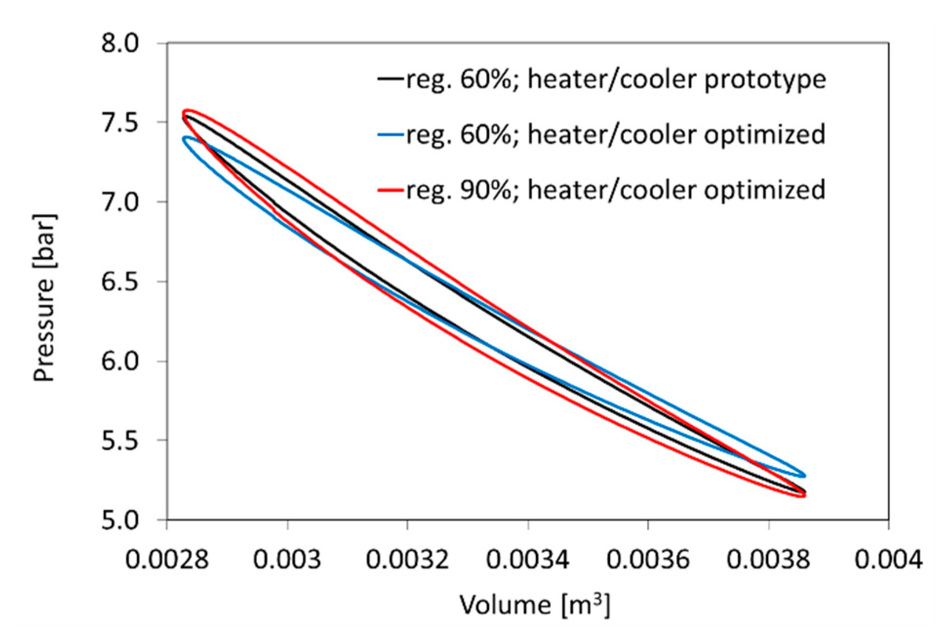
Figure 18 presents a summary of the simulation results obtained for three cases of the Stirling engine configuration: (1) the original ones used in the prototype, (2) for the optimized design of the heater and cooler and (3) with increased regenerator effectiveness up to 90% (design modification).
In case 1 the design parameters at which the engine prototype was tested are used (they are presented in
Table 1, regenerator efficiency 60%). In case 2, the heat exchange surfaces in the heater and the cooler are modified, while the diameters of pipes remain the same (4 mm). As a result, the ratio of the heat exchange surface and the dead volume, occupied by working gas in a given exchanger, remains unchanged. The selection of the heat exchange surfaces mentioned above was optimized due to the efficiency of the engine and was performed using the numerical optimization procedure. In case 3, a structural change of the regenerator was considered, using a filling with a higher heat exchange area, while maintaining the same porosity (finer elements), to obtain a higher regenerator efficiency. At the same time, it was assumed that the heater and the cooler are made of tubes with smaller diameters (1 mm), their number and length were determined by the calculated heat exchange area. This solution enabled a significant reduction of dead space in regenerator. Heat exchange area in the heater and the cooler were optimized the same way as it was described in case 2.
All cases are related to the heating temperature of 350 °C and a charge pressure of 6 bar. The introduction of these modifications leads to an increase in both engine efficiency and power output (
Table 3). Especially the latest modification including the reduction of the dead space by changing the internal diameter of the tubes in heat exchangers from 4 mm (prototype) to 1 mm, leads to an increase in engine power by 220% as compared to the prototype solution.
7. Conclusions
The operating parameters of a prototype alpha type Stirling engine presented in the paper indicate that for a moderate temperature level, increasing charge pressure is only beneficial to a certain level. A further increase in charge pressure causes an increase in indicated power, but the efficiency no longer increases. This is happening due to the non-optimal selection of the ratio of heat exchange surface to the dead volume included in heat exchangers. In order to improve the operating parameters of the engine, the adiabatic model has been used. The model was calibrated using experimental data. The calibration has been performed assuming that the average value of the indicated work, for the considered operating points, cannot differ for model and experimental data by more than 1%.
As a result of the calibration, regenerator effectiveness characteristic has been obtained, which was the last missing data in the model. Due to the high uniqueness of the regenerator designs used in prototype solutions, this is a much more accurate method of determining its characteristics than the use of experimental formulas worked out for similar constructions.
It can be concluded that in the tested temperature range, the regenerator effectiveness is not explicitly related to this parameter. In the pressure range above 4 bar it can be seen that the increase in temperature also increases the efficiency, but for pressures below 3 bar the regenerator effectiveness is higher at a temperature of 350 °C rather than 400 °C. In the case of rising charge pressure a general tendency to increase regenerator effectiveness was observed, regardless of the heating temperature. Finally, it was proposed to use the simplified characteristics of the regenerator effectiveness taking into account the linear relation between charge pressure and regenerator effectiveness.
Simulation tests were carried out while optimizing the heat exchange surface of the heater and regenerator due to the indicated efficiency. The obtained results are therefore a set of optimal design parameters for given operating conditions (heating temperature, charge pressure).
On the basis of the simulation tests carried out using the adiabatic model, it can be stated that the engine power and the indicated efficiency increase with the charge pressure. The indicated power and efficiency also increase with the regenerator effectiveness. This is the result of an increasing amount of heat that is delivered from the regenerator during the expansion process, and thus a reduction of the amount of heat that must be supplied from the outside.
Assuming further development of the regenerator and use of smaller diameter tubes in the heat exchangers, the modified design of the engine has been calculated. This configuration would theoretically increase the indicated efficiency up to 19.5% (5.5% prototype) and the indicated power up to 369 W (114 W prototype).
The results presented in the paper indicate that there is an effective way to use a Stirling engine to generate electricity from the waste heat at moderate temperatures. However, it is necessary to optimize the heat exchange surface and the volume occupied by the working gas in the heat exchangers for the applied heating temperature and charge pressure. The paper presents a new experimental - simulation method enabling the determination of optimal design parameters of a Stirling engine due to the engine efficiency. This method is based on the use of an iterative computational procedure, whose schematic diagram is described in
Figure 8. Simulation results compatibility with the experiment, however, depends mainly on the accuracy of the regenerator efficiency estimation, as well as accuracy of the hydraulic resistance estimation. Hence, modelling of the regenerator’s efficiency and its hydraulic resistance requires further development. It should be remembered that the requirements set for the regenerator, high efficiency and low hydraulic resistance, are not in line. For example, by increasing the number of elements of the regenerator’s filling, the efficiency is rising, while it causes an increase of hydraulic resistance and the dead volume, which have negative impact on the efficiency of the entire Stirling engine.


