Article

Influence of Hydrophobic Fin Configuration in Thermal System in Relation to Electronic Device Cooling Applications

by
Shahzada Zaman Shuja
1,
Bekir Sami Yilbas
1,2,3,* and
Hussain Al-Qahtani
1
1
ME Department, King Fahd University of Petroleum and Minerals, Box 1913, Dhahran 31261, Saudi Arabia
2
Center of Excellence in Renewable Energy, King Fahd University of Petroleum and Minerals, Dhahran 31261, Saudi Arabia
3
K.A.CARE Energy Research & Innovation Center, Dhahran 31261, Saudi Arabia
*
Author to whom correspondence should be addressed.
Energies 2020, 13(7), 1631; https://doi.org/10.3390/en13071631
Submission received: 13 February 2020 / Revised: 10 March 2020 / Accepted: 25 March 2020 / Published: 2 April 2020

Abstract

:
In this study, heat and flow analysis of the cooling system incorporating fins with hydrophilic and hydrophobic wetting surfaces has been considered in relation to electronic cooling applications. Temperature and velocity fields in the solution domain are simulated for various fin numbers and sizes. A temperature parameter is introduced to assess the thermal performance of the system. Fin count is introduced to formulate the number of fins in the solution domain. The Nusselt number and pressure drop between the inlet and exit ports due to different fin configurations of the cooling system for various fin counts are presented. It is found that the temperature parameter attains high values for large sizes and small fin counts, which is more pronounced for low Reynolds numbers. Increasing number of fins results in almost uniform flow distribution among the fin, which is more pronounced for the hydrophobic fin configuration. The Nusselt number attains larger values for the hydrophilic fin configuration than that corresponding to the hydrophobic fin, and it attains a peak value for certain arrangement of fin count, which differs with the Reynolds number. The pressure drop between the inlet and exit ports reduces for hydrophobic fin; hence the slip velocity introduced for hydrophobic fin improves the pressure drop by 6% to 16% depending on the fin counts in the cooling system.

1. Introduction

Cooling of electronic devices by extended surfaces offers significant advantages over other cooling techniques; particularly cooling for small size devices. Active cooling of fins provides efficient heat transfer rates from surfaces either by keeping temperature constant or by maintaining constant rate of heat removal from the surfaces. Pumping power is required when liquids are used as a coolant in the active cooling system. The need for pumping power becomes detrimental when the viscous and form drags are large due to closely spaced and staggered fins in the cooling system. In order to minimize the viscous dissipation and drag forces, the slip conditions on the fin surfaces can be created through altering the wetting state of fin surfaces from hydrophilic to hydrophobic. The hydrophobic wetting state requires texturing of surfaces towards forming micro/nano pillars. The air gap located in between micro/nano pillars lowers the contact area of the liquid on the fin surfaces, and results in the slip condition on the surface while reducing overall pressure drop in the staggered fin arrangement. On the other hand, the overall area of the liquid contact reduces on the fin surfaces, which in turn partially lowers the heat transfer rates from the fin surfaces to the liquid coolant. The arrangement of hydrophobic wetting state of the fin surfaces has a coupled effect on the pressure drop and heat transfer of the cooling system. In this case, the pressure drop and heat transfer rates can be reduced simultaneously for the hydrophobic fin configuration. However, the ratio of power loss over the heat transfer rates remains interesting for evaluating the hydrophobic fin configuration in the cooling system. The influence of hydrophobic wetting state of the fins on the pump power loss and heat transfer rates changes with the number of fins and fin orientations on the heat transferring surface. Consequently, investigation of the influence of the hydrophobic wetting state of the fin on the heat transfer rates and pressure drop in an active cooling system becomes essential.
Thermal performance of cooling systems incorporating fins with various configurations was studied earlier [1,2,3,4,5,6,7,8,9,10,11,12,13,14,15,16,17]. Although fins interrupt the flow in the cooling system, proper arrangement of fin configuration, such as non-uniform fin distribution, improves the performance of the thermal systems [1]. Fin orientation such as different angles and shapes also influence the heat transfer characteristics of the surface [2]. Fin design incorporating fin perforation [3], or using fluids with nano-size particles, such as graphene [4], enhances the cooling system performance. Introducing parallel plate -finned- heat sink with a heat shield [5], transverse rib arrangements [6], and using highly conductive fin materials [7] further improves the cooling effectiveness of the surface. Fins can also be used effectively under high heat fluxes [8]. Micro-fin improves the cooling effectiveness of the surfaces subjected to high heat fluxes [9], particularly convex and hydrofoil shape fin designs contributes to cooling effectiveness. Moreover, fin arrays or micro-pillars can be used for various heating and cooling applications. Non-uniform micro-pillars are found to be effective in transfer enhancement, particularly pool boiling process on a silicon chip [10]. The passive micro pump system utilizing the tapered microchannel and sharp microstructures is found to be effective on microchannel cooling [11]. On the other hand, hydrophobic wetting state of the fin surfaces remains important for minimization of the power required for circulating the working fluid in the cooling system. Generation of artificial surface roughness on the micro-fin heat sink fin provides the improved performance for thermoelectric generator and microprocessor cooling applications [12]. The wetting state and the fin shape influence the heat transfer rates from surfaces [13]. In the case of increasing hydrophobic state to superhydrophobic state of fin surfaces, significant enhancement of heat transfer rates from the fin surfaces is observed [14]. The hydrophobic wetting state also plays an important role when the fin surface is subjected to frosting and defrosting [15]—particularly the hydrophobic wetting state, which influences the amount of water retention from surfaces during the defrosting [16]. Similar arguments also become relevant to the hydrophobic wetting state of the metallic surfaces [17]. Moreover, the fin surfaces with hydrophobic wetting state can be utilized to minimize the fouling rates in heating and cooling applications of surfaces, since they result in dust repelling of the dust particles from surfaces [18]. In addition, adhesion between the settled particles and the surface remains weak as the wetting state of the surface becomes hydrophobic, which enables the hydrophobic surfaces being used for biomedical engineering [19] and for anti-fouling applications in various membrane technologies [20,21,22]. Pressure drop in heat exchangers is one of the challenging problems towards maintaining the low pumping power of circulating the working liquid. Hydrophobic wetting state of the surface results in a low pressure drop along the heat transferring surfaces [23]. The minimization of pressure drop is mainly associated with generating slip velocity on the micro-textured surfaces [24]. This is particularly important for drag reduction in micro-channel flow; in which case, the trapped air bubbles can be maintained on the surface for prolonged periods of time which maximizes drag reduction in the channel [25]. In addition, using the hybrid wetting pillar surfaces improves the heat transfer rates in nucleate boiling, particularly at low heat fluxes [26]. Thermal optimization of microchannel heat remains important because of efficient operation of the thermal system. Various fin configurations can be considered such as rectangular, oblique, cylindrical, etc. [27,28]. Several algorithms are suggested towards microchannel fins optimization; however, combination of genetic algorithm with the finite element methods is one of the interesting methods adopted for the thermal optimization of microchannel fins [29]. Another effective approach for the optimization study is the multi-objective optimization via using the weighted sum method with the genetic algorithm [30].
Although flow over hydrophobic surfaces and influence of slip velocity on the frictional drag and heat transfer was studied previously [16,17,18], the main focus was to improve the heat transfer rates and pressure drop on flat surfaces. In addition, the heat transfer enhancement and cooling effectiveness for extended surfaces, such as fin, are studied earlier [31], the main challenge was to minimize the pressure drop either by introducing the fin geometric modifications [9] or utilizing the porous structures on the fin surfaces [32]. On the other hand, the liquid cooling of surfaces incorporating the fin in the cooling system provides opportunity to alter the wetting state of the fin surfaces from hydrophilic to hydrophobic state towards generating the slip condition on the fin surfaces. Since multiple fins are used in the cooling system, the geometric arrangement of the fin, in terms of size (diameter) and number of fins, equally affects the cooling performance of the system. Consequently, in the present study, innovative design of a cooling system incorporating the hydrophobic staggered pin fins is considered. The heat transfer rate and pressure drop in the system are assessed for various fin configurations while using water as the working fluid. The influence of Reynolds number on temperature parameter and pressure drop in the system is analyzed.

2. Heating and Flow Analysis

A schematic view representing the heat exchanging system is shown in Figure 1. The inlet and exit port, and fin heights are considered to be the same as the cavity width (0.04 m). Simulations of different configurations through a hydrophobic pin finned rectangular channel are carried out finding the optimal configuration that would result in maximum heat removal rates. The configuration of a heat exchanging system is altered to account for the influence of fin sizes and spacing on the heat transfer rates. In addition, influence of hydrophobic fin characteristics on the heat transfer and pressure drop is analyzed. Fin count (n) is introduced to estimate the number of fins (m) in the cavity (solution domain). In this case, a fin count of n represents the number of fins (m) in the cavity via relation: m = ( n × n ) + ( n 1 ) 2 ), e.g., a fin count of n = 4 corresponds to m = 25 fins in the solution domain (Figure 1b). The total area of the fins in the cavity is 1/3 of the cavity cross-sectional area of the cavity and it is kept constant for all fin count configurations. Hence cross-sectional area of each fin is fin total area over number of fins (m).

2.1. Governing Equations

Water is considered as the working fluid in the system. The steady and laminar flow situation is incorporated in the analysis. The conservation equations for mass, momentum and energy for the flow system can be presented as:
Continuity of mass:
V = 0 ,
Momentum equation incorporating buoyancy effect:
ρ ( V ) V = p + μ 2 V ρ g β ( T T r e f ) ,
Energy equation:
ρ c ( V ) T = p + k 2 T + μ Φ ,
Viscous dissipation
Φ = ( 2 ( ε : ε ) ) 2 ;   where   ε = 1 2 ( V + ( V ) t ) ,
where V is the flow velocity vector, p is the pressure, T is the temperature, g is the gravity, Tref is the reference temperature (293 K), ρ is the fluid density, µ is the viscosity, c is the fluid specific heat, k is the fluid thermal conductivity and β is the volumetric thermal expansion coefficient.
The Reynolds number is determined incorporating the cavity inlet port length Lin (Lin = 0.005 m), i.e., R e = ρ L i n V i n μ , where ρ is fluid density, Vin fluid velocity at the cavity inlet port, and µ is fluid viscosity. The Nusselt number is determined from: N u = h ¯ D k , where h ¯ is the overall heat transfer coefficient, which is evaluated via integration of local heat transfer coefficient over the surface area of fins, D is the fin diameter. The pressure coefficient is defined through C p = Δ P 1 2 ρ V i n , where ΔP is pressure difference between inlet and exit ports and Vin is the inlet velocity.

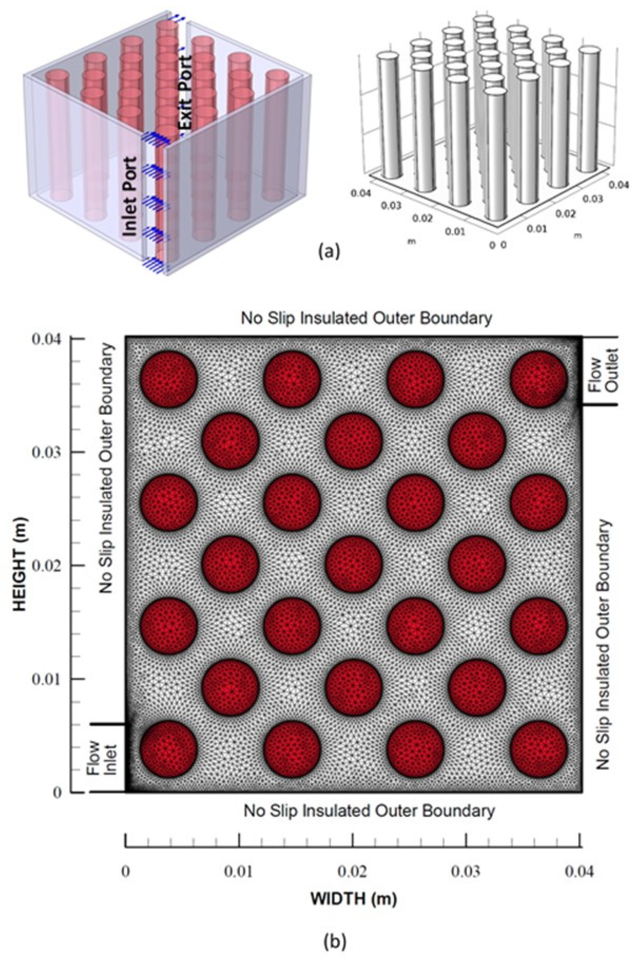
2.2. Boundary Conditions

At the solid surfaces around the cavity no slip boundary condition is adopted. In the case of fin surfaces, simulations are carried out separately for slip and no-slip boundary conditions. This enables us to evaluate influence of slip boundary condition on heat transfer rates and pressure drop. The boundary conditions are shown schematically in Figure 1. The slip boundary condition resembles the hydrophobic surface while no slip boundary corresponds to hydrophilic surface. Hence, slip boundary yields a slip velocity at the solid surfaces, i.e., u s = L s u / n , where us is the slip velocity of the fluid near the wall, Ls is slip length, which is taken as 5 µm, based on roughness parameter, and n is the direction normal to the surface. It should be noted that roughness parameter represents the ratio of pillar area over the projected area of the surface. Due to hydrophobic wetting of the surface, the temperature jump on the boundaries is employed which is T s T w = L t T / n where Ts is the fluid temperature at the wall and Tw is the wall temperature. Lt is the temperature jump length and is a thermal resistance length at the solid-liquid interface, which may be related with slip length via Prandtl number (Pr) as L T = L s / Pr . Outer surfaces of the system are assumed to be thermally insulated, which yield T / n = 0 , where n is normal to the boundary.
At the system inlet, the Reynolds number is varied as 100 Re 500 and the water temperature is set to Tinlet = 300 K. At the bottom of the fins a constant heat source of 100 W is introduced.
Constant pressure boundary is considered at the system exit, (p = 0 gauge,) which corresponds to the open atmospheric condition. Temperature continuity is also considered at the exit, i.e., T / x = 0 .

2.3. Numerical Implementation

The finite element method is adopted to solve the continuity, momentum and energy equations for a carrier incompressible fluid. The Galerkin method is used to discretize the equations incorporating the relevant boundary conditions. The flow parameters including velocity, pressure, and temperature are discretized as:
V k ( x , y ) = i = 1 n N i k v ( x , y ) V i ,
p ( x , y ) = i = 1 n N i p ( x , y ) p i ,
T ( x , y ) = i = 1 n N i T ( x , y ) T i ,
where Ni represents the shape function, n corresponds to the node number in the element, and pi is the nodal pressure, Vi is the nodal velocity, and Ti is the nodal temperature. The shape function includes the triangular elements. The residuals resulting from the numerical solutions take the form:
Continuity
Π 1 ( N i v , V k ) = 1 ,
Momentum
Π 2 ( N i v , N i p , N i T , V k , p , T ) = 2 ,
Energy
Π 3 ( N i v , N i T , V k , T ) = 3 ,
where, j represent the residuals resulted from the discretization process. To reduce the errors related to the residuals, interpolation functions are introduced while setting the residuals orthogonal to these functions. Hence, consideration of orthogonality yields the relation:
Ω N i p Π 1 d Ω = Ω N i p 1 d Ω = 0 ,
Ω N i v Π 2 d Ω = Ω N i v 2 d Ω = 0 ,
Ω N i T Π 3 d Ω = Ω N i T 3 d Ω = 0 ,
where Ω represents the space in the domain considered. Introducing the Gauss-divergence theorem, the matrix form of the discretized conservation equations becomes:
Momentum
[ C ] { V } { U } + [ L ] { U } { U } = { f } ,
Energy
[ D ] { V } { T } + [ K ] { T } { T } = { g } ,
with
V = { u v }   and   U = { u v p } ,
Here, [C] and [D] matrices correspond to the convection part of the momentum and the energy, respectively while [L] and [K] are the diffusion part of the momentum and the energy. It can be noted that [L] incorporates the continuity constraint and it is utilized in finding the fluid pressure. Moreover, the {f} and {g} vectors correspond to the forcing functions related to body force, surface forces, and volumetric heat source. The convergence results are considered as the error between two consecutive iterations for each variable becomes less than 10−4, i.e., |Ψn+1Ψn| ≤ 10−4, here n represents the iteration number and Ψ is a variable corresponding to the flow parameters such as velocity, pressure, and temperature.

2.4. Mesh Generation

In the solution domain, fine meshes are located in the region where the fluxes are high. Figure 1 depicts the mesh generated in the solution domain.

2.5. Thermo-Physical Properties

The water properties used are described by the equations provided in Table 1, whereas the thermo-physical properties of Aluminum are considered constant and are given in Table 2.

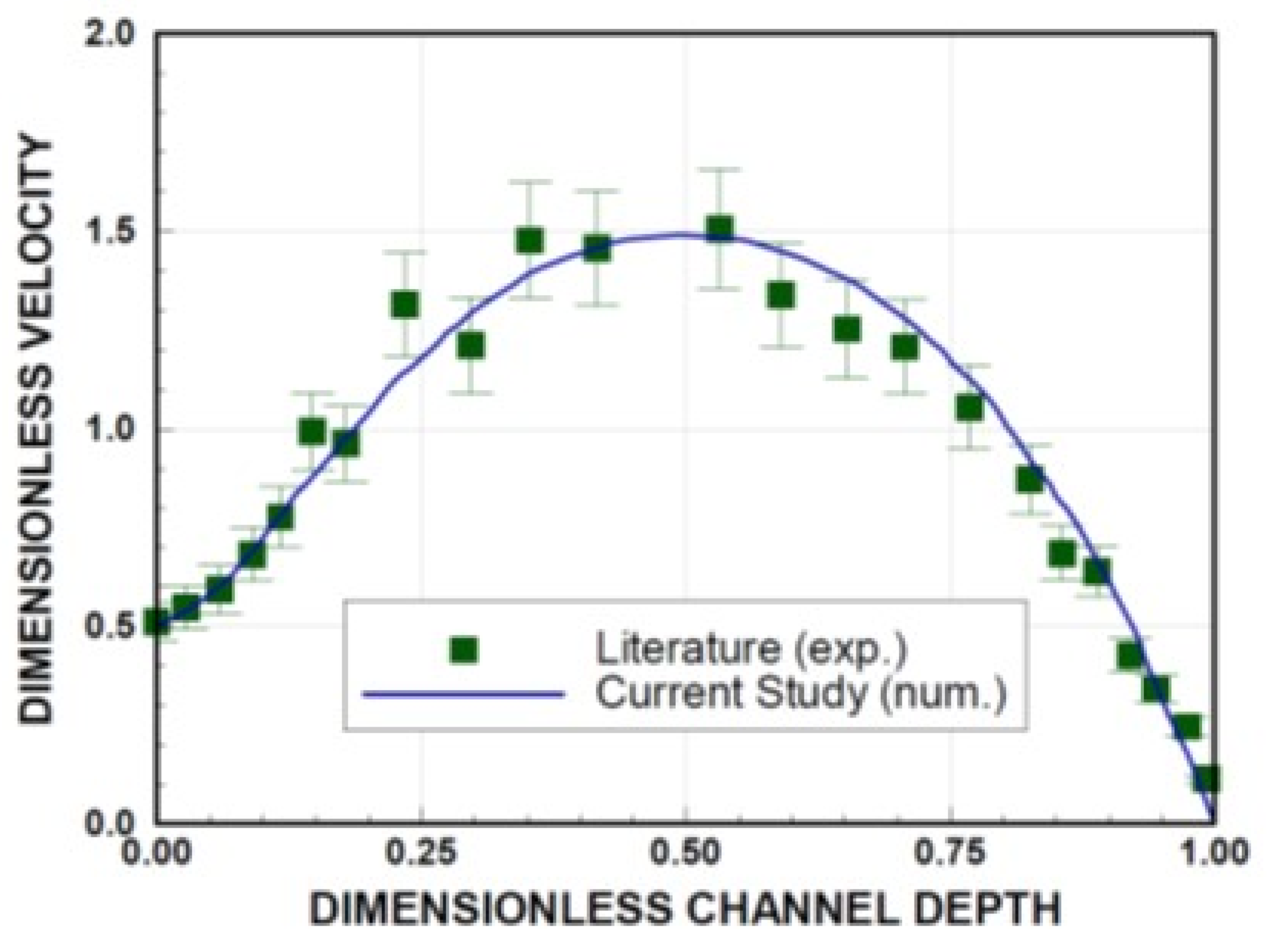
2.6. Model Validation

To validate the model study, the data provided in an early study [34], incorporating hydrophobic and hydrophilic surfaces, is used. The simulation conditions are changed adopting those used in the early work. The predictions of the present study and findings of the early work for dimensionless velocity with dimensionless channel depth is given in Figure 2. It is evident that the current predictions of dimensionless velocity agree well with those obtained from the early work [34], i.e., the difference between both studies are considerably small. The velocity is non-dimensionalized through the mean velocity of the flow while channel depth is normalized by the maximum channel depth, which are consistent with the early work [24].

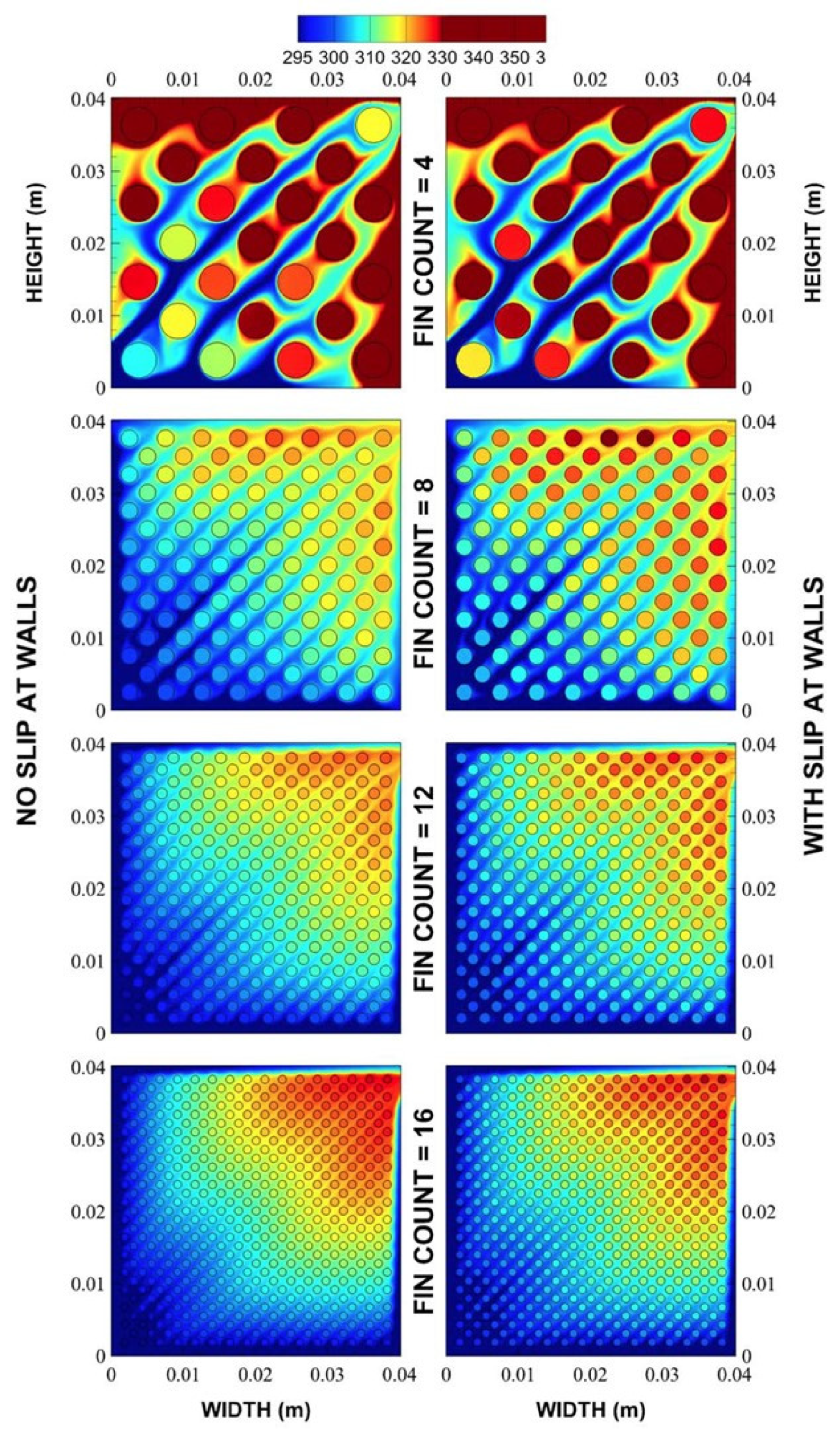
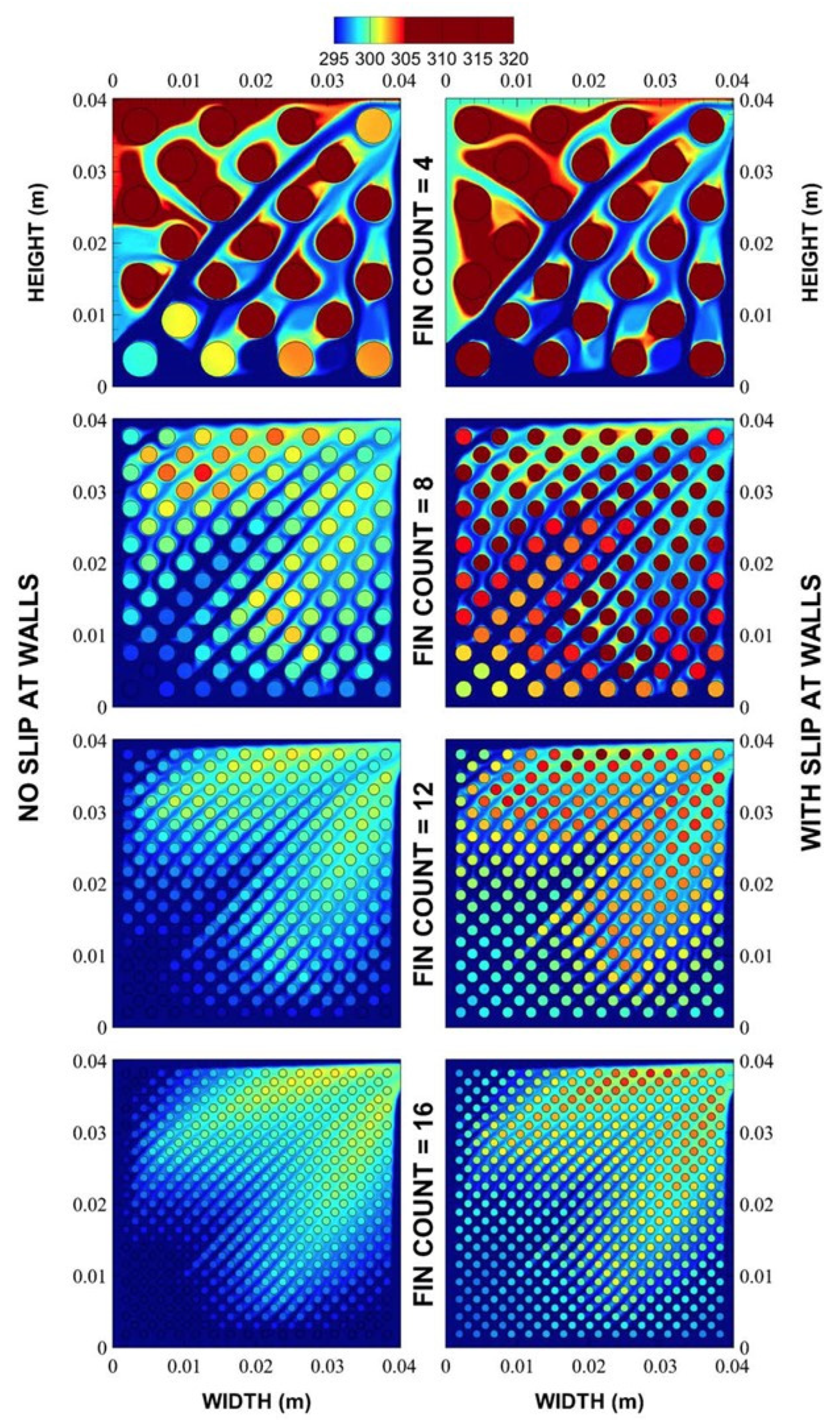
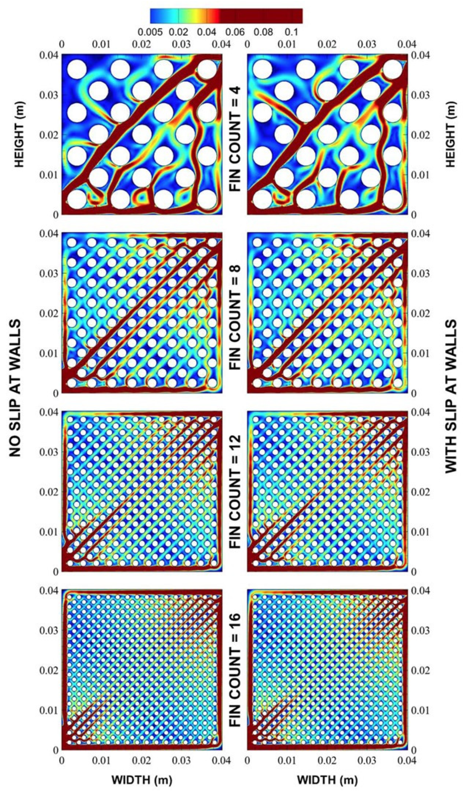
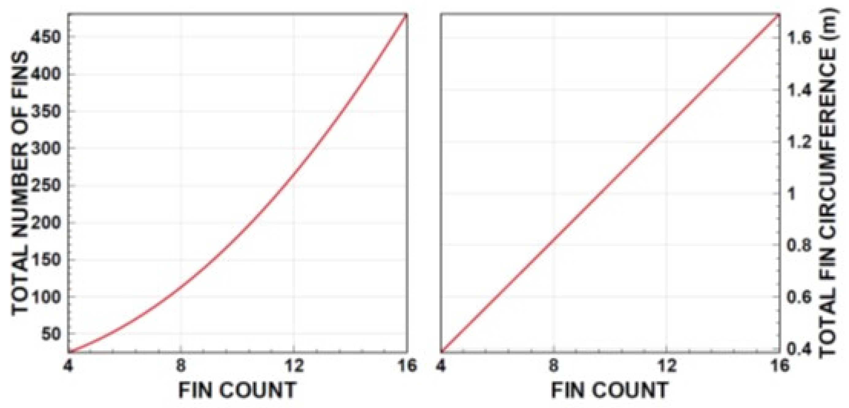
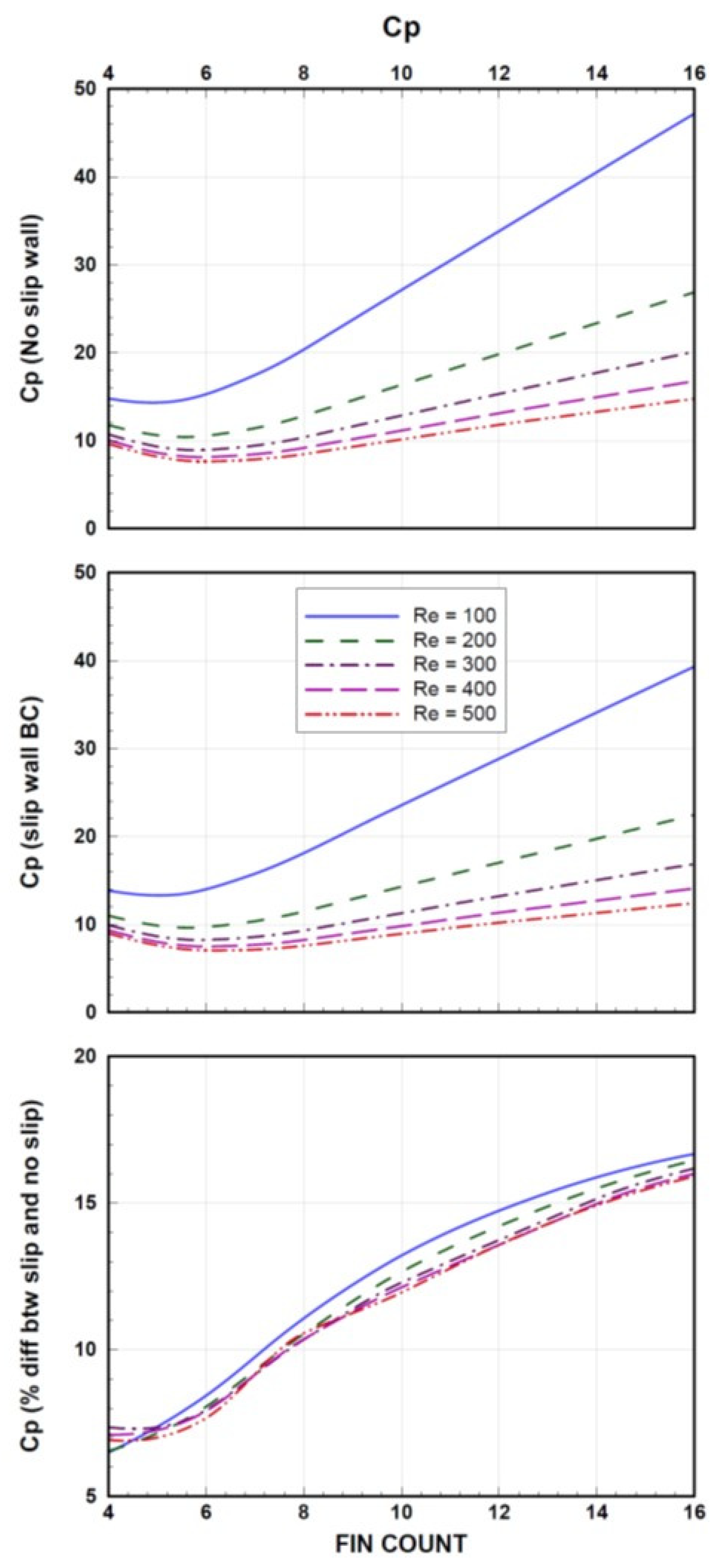
3. Results and Discussion

Innovative design of the hydrophobic fin configuration is introduced in relation to electronic cooling applications. In the analysis, various sizes of circular fin with different staggered arrangements are incorporated in the cooling system, and the resulting heat transfer rates and pressure drop are analyzed for various operating Reynolds numbers.
Figure 3 shows temperature distribution in the solution domain for various fin counts (number of fins) for two cases: (i) simple fin with hydrophilic wetting state (no slip) and (ii) fin with hydrophobic wetting state (with slip).
It should be noted that the fins are located in the cavity forming a cooling system, which has inlet and exit ports (Figure 1) and the working fluid (water) enters into the inlet port and exits from the outlet port. Since the hydrophobic fin surfaces have texture morphology and roughness parameter, (which is defined through the ratio of pillar area over the projected area of surface [35], considered to be 0.52 in the current study), therefore thermal resistance is formed on the fin surfaces because of the air pockets captured in between the surface pillars. Hence, the surface thermal resistance due to texture morphology is incorporated in the analysis. This causes a thermally resistive layer between the fin surface and the working fluid. Consequently, fin surface temperature remains higher for the hydrophobic wetting state than that corresponding to the hydrophilic wetting state. Increasing the fin numbers reduces the size of high temperature region in the solution domain; however, further increase in the fin size promotes the size of high temperature region. It should be noted that further increase in the number of fins lowers the flow passages in between the fins. This suppresses the forced convection heat transfer from fin to the working fluid; hence, a high temperature of the flow in the region towards the exiting of the port becomes larger in size. In the case of the hydrophobic fin, the slip condition on the fin surface lowers the shear strain of the flow in the passages between the fin surfaces, resulting in reduction of the working fluid temperature. In addition, the hydrophobic fin suffers from surface thermal resistance due to surface texture morphology; hence, it contributes to the attainment of low temperature of the working fluid. On the other hand, in the case of high Reynolds number (Figure 4) the high velocity flow passes diagonally in between the inlet and exit ports without being sufficiently heated by the fins. This is more prominent for larger diameter and coarse fins in the solution domain. In the case of dense fins and a large number of fins, fluid temperature remains low in the region of the intake and low temperature region extends almost in the middle section of the solution domain. Fluid temperature increases in the exit port region of the solution domain; however, temperature increase is not as high as that corresponding to the low Reynolds number (Re = 100). In addition, the hydrophobic wetting state of fins results in high fin temperature in the exiting region. This behavior is true for all number of fins incorporated in the solution domain.
Figure 5 and Figure 6 show velocity distributions in the solution domain for hydrophobic and hydrophilic fin and various number of fins.
The parameters in Figure 5 and Figure 6 are the same as those of Figure 3 and Figure 4. In general, flow velocity remains high along the diagonal direction in the cavity because of less resistance to flow along this direction. Moreover, flow velocity in the regions near the inlet and exit ports remains higher than the other locations. This is more pronounced for smaller number of fin configurations, i.e., the flow emanating and merging from inlet and exit port regions remains at relatively higher velocities than the other regions. Increasing the number fins gives rise to almost uniform distribution of the flow velocity around the fins, which is true for hydrophobic and hydrophilic fin arrangements. The flow pattern resulted around the fins becomes almost similar for high Reynolds number (Re = 500, Figure 6), provided that the maximum flow velocity is higher for Re = 500 than that of Re = 100. However, flow tends to remain at high velocity along the diagonal direction in the inletting and exiting port regions. This behavior is true for all number of fins. Consequently, flow uniformity among the fins is suppressed by the high Reynolds number at the cavity inlet.
Figure 7 shows the temperature parameter ( φ = T m a x T i n T i n ), where T m a x is the maximum temperature in the solution domain and Tin is the fluid inlet temperature) in the solution domain with fin count for various Reynolds numbers. It should be noted that fin count of n represents the m = ( n × n ) + ( n 1 ) 2 number of fins (m) in the cavity (solution domain), e.g., a fin count of n = 4 corresponds to 25 fins in the solution domain (Figure 1b). The temperature parameter attains high values for low fin counts; in this case, the maximum fluid temperature attains high values. Reducing the Reynolds number lowers the temperature parameter; however, as the fin count increases, the differences in the temperature parameter due to Reynolds numbers become small. Hence, the influence of fluid velocity on the maximum temperature in the solution domain becomes small with increasing fin counts.
This is attributed to the fin spacing, i.e., increasing fin counts results in almost uniform-like velocity distribution inside the solution domain (Figure 6) while lowering the temperature parameter. In the case of hydrophobic fin surfaces, the temperature parameter behaves similarly as that of hydrophilic configuration. However, the maximum temperature remains slightly higher for the hydrophobic configuration than that of the hydrophilic, which gives rise to slightly higher temperature parameter as compared to that corresponding to the hydrophilic case. This behavior is related to the thermal resistance developed in the surface vicinity of the hydrophobic fin because of the surface texture morphology. The difference in the maximum temperature for both cases reduces with increasing fin counts and Reynolds number. This situation can also be seen from Figure 7, in which the percentile difference in the temperature parameter due to hydrophobic and hydrophilic cases is also shown. The decay of percentile difference is because of the total length of the fin circumference in the solution domain. In this case, increasing fin counts increases the total length of the fin circumference (Figure 8). This in turn enhances the fluid contact length around the fin surfaces while enhancing the heat transfer rates from the fins to the working fluid. Hence, the occurrence of a localized high temperature in the fins is avoided with increased fin counts. Although the thermal resistance formed on the surface for the hydrophobic fin, due to texture morphology, suppresses the heat transfer and enhances fin temperature increase, the extended surfaces created by the increased fin counts minimizes the value of the maximum temperature on the fin surfaces.
This behavior is attributed to the increased convection current in between the fins with increasing Reynold numbers. Since the small fin counts results in small wetting circumference of the fin (Figure 8), the surface area of the fin seen by the working fluid remains small for the small fin counts, i.e. the heat transfer and Nusselt number reduces for small fin counts. Moreover, the Nusselt number increases reaching to its maximum for fin counts in the range of 8–12. This shows that small and large values of the fin count do not yield the maximum Nusselt number. The peak value of the Nusselt number changes with the Reynolds number. In this case, increasing Reynolds number causes the occurrence of the peak Nusselt number at smaller fin counts than that corresponding to the large fin counts. The Reynolds number has an inverse effect for the dependence of the Nusselt number on fin counts. Increasing fin counts enhances the overall circumference of the fin in the solution domain (Figure 8); however, the heat transfer from fin to working fluid is affected by the velocity distribution in between the fin.
Figure 9 shows Nusselt number variation with the fin counts for various Reynolds numbers. In general, increasing Reynolds number enhances the Nusselt number, which is more pronounced for small fin counts.
Hence, at some combination of the fin counts, the heat transfer rate improves only when fluid velocity remains in the affective range of the corresponding fin counts. Consequently, a care must be taken to maximize the Nusselt number when operating of the cooling system with the fin. In another words, for a designed cooling system incorporating the fin, the operating parameters including the flow velocity must be selected properly to attain the peak Nusselt number. In the case of the hydrophobic surface, the Nusselt number attains relatively lower values than that of the hydrophilic fin configuration. The trend of the Nusselt number variation follows almost similar to the hydrophilic case. The attainment of low Nusselt number is associated the thermal resistance introduced in the surface vicinity of the fin due to texture morphology. Figure 10 shows pressure drop across the inletting and exiting ports of the solution domain with fin counts. Pressure drop significantly increases with increasing fin counts due to the fluid shear resistance in between the fin. Increasing Reynolds number enhances the pressure drop across the inletting and exiting ports of the solution domain, which is more pronounced for the large fin counts. In the case of hydrophobic fin configuration, the pressure drop becomes considerably smaller than that corresponding to the hydrophilic fin surfaces. The percentage of pressure drop due to hydrophilic and hydrophobic fin configurations varies with in between 6% to 16%; in which case, the percentage of the pressure drop increases as the fin count increases. Consequently, introducing the hydrophobic surface arrangement of fin lovers the pressure loss across inletting and exiting ports. This becomes clearly visible for large number of fins in the solution domain (large fin counts).

4. Conclusions

Heat transfer analysis for hydrophilic and hydrophobic circular fin configurations is considered in relation to the electronic device cooling applications. Influence of fin counts (number of fin) and sizes (diameter) on the flow and thermal fields are simulated for various Reynolds numbers at the inlet port. The temperature parameter is introduced to assess the maximum temperature variation within the fin for various flow Reynolds numbers. A pressure drop in between the inletting and exiting ports of the solution domain, due to hydrophobic and hydrophilic fin configurations, is predicted and the influence of the Reynolds number on the pressure drop is discussed. It is found that the flow develops channels diagonally in between the inletting and exiting ports of the solution domain for small fin count. Increasing fin counts results in an almost uniform distribution of velocity in between the fin. Introducing the hydrophobic fin configuration improves further the flow uniformity in the solution domain. The temperature parameter attends low values with increasing fin counts, which is more pronounced for high Reynolds numbers. In this case, increasing fin counts enhances the overall wetted length of the fin surfaces in the solution domain. The temperature parameter attains slightly high values for the hydrophobic fin configuration. The thermal resistance in the surface vicinity of the fin, due to texture morphology, is responsible for the slightly large temperature parameter. The Nusselt number increases to attain its peak for a certain range of fin counts depending on the Reynolds number. Consequently, the efficient operation of the cooling system requires proper setting of the Reynolds number at the inlet port. The Nusselt number reduces for the hydrophobic fin configurations, which is more pronounced for large fin counts. The pressure drop in between the inlet and exit ports increases with increasing fin counts; however, implementing hydrophobic fin configuration reduces the pressure drop by 6% to 16%. This is mainly a slip flow boundary condition generated by the hydrophobic fin surfaces. The present study gives insight into the comparative examination and assessment of the hydrophilic and hydrophobic fin in the cooling system and provides useful information on the Nusselt number and pressure drop in the flow system incorporating hydrophilic and hydrophobic fin.

Author Contributions

Conceptualization, S.Z.S., B.S.Y., and H.A.-Q.; methodology, S.Z.S. and B.S.Y.; software, S.Z.S.; validation, S.Z.S., B.S.Y., and H.A.-Q.; formal analysis, B.S.Y. and H.A.-Q.; investigation, S.Z.S. and B.S.Y.; resources, H.A.-Q.; data curation, S.Z.S., B.S.Y., and H.A.-Q.; writing—original draft preparation, S.Z.S., B.S.Y., and H.A.-Q.; writing—review and editing, S.Z.S., B.S.Y., and H.A.-Q.; visualization, B.S.Y. and H.A.-Q.; funding acquisition. All authors have read and agreed to the published version of the manuscript.

Funding

This research was funded by the King Fahd University of Petroleum and Minerals, Project No. IN171004.

Acknowledgments

The authors acknowledge the support of the Deanship of Scientific Research via supporting the project IN171004, King Fahd University of Petroleum and Minerals, Dhahran, Saudi Arabia and King Abdullah City for Atomic and Renewable Energy (K.A.CARE) for the support.

Conflicts of Interest

The authors declare no conflicts of interest. The authors also declare no personal circumstances or interest that may be perceived as inappropriately influencing the representation or interpretation of the reported research results. The funders had no role in the design of the study; in the collection, analyses, or interpretation of data; in the writing of the manuscript; or in the decision to publish the results.

Nomenclature

cSpecific heat (J/kgK)
CPPressure loss factor
gGravity (m/s2)
kThermal conductivity (W/mK)
LsSlip length (m)
LTThermal resistance length (m)
nFin count
NuNusselt number
PPressure (kPa)
PrPrandtl number
ReReynold number
TTemperature (K)
TsLiquid temperature at wall interface (K)
TwSolid wall temperature at interface (K)
VsSlip velocity (m/s)
∂u/∂nRate of fluid strain on slip surface (1/s)
VVelocity vector (m/s)
Greek letters
εStrain rate tensor (1/s)
βVolumetric thermal expansion coefficient (1/K)
μViscosity (Pa.s)
ϕTemperature parameter
ΦViscous dissipation (1/s2)
ρDensity (kg/m3)
Subscripts
maxmaximum
minminimum
refreference

References

  1. Qian, M.; Li, J.; Xiang, Z.; Yan, C.; Hu, X. Effect of Pin Diameter Degressive Gradient on Heat Transfer in a Microreactor with Non-Uniform Pin-Fin Array under Low Reynolds Number Conditions. Energies 2019, 12, 2702. [Google Scholar] [CrossRef] [Green Version]
  2. Shyu, J.-C.; Chang, T.; Lee, S.-C. A Numerical Study on Natural Convection Heat Transfer of Handheld Projectors with a Fin Array. Energies 2017, 10, 266. [Google Scholar] [CrossRef] [Green Version]
  3. Tijani, A.S.; Jaffri, N.B. Thermal analysis of perforated pin-fins heat sink under forced convection condition. Procedia Manuf. 2018, 24, 290–298. [Google Scholar] [CrossRef]
  4. Li, D.; Yang, C.; Yang, H. Experimental and numerical study of a tube-fin cool storage heat exchanger. Appl. Therm. Eng. 2019, 149, 712–722. [Google Scholar] [CrossRef]
  5. Shaalan, M.R.; Saleh, M.A.; Mesalhy, O.; Elsayed, M.L. Thermo/fluid performance of a shielded heat sink. Int. J. Therm. Sci. 2012, 60, 171–181. [Google Scholar] [CrossRef]
  6. Chang, S.W.; Su, L.M.; Yang, T.L.; Chiou, S.F. Enhanced heat transfer of forced convective fin flow with transverse ribs. Int. J. Therm. Sci. 2004, 43, 185–200. [Google Scholar] [CrossRef]
  7. Hajmohammadi, M.; Ahmadian, M.; Nourazar, S. Introducing highly conductive materials into a fin for heat transfer enhancement. Int. J. Mech. Sci. 2019, 150, 420–426. [Google Scholar] [CrossRef]
  8. Tu, J.; Yuen, W.; Gong, Y. An Assessment of Direct Chip Cooling Enhancement Using Pin Fins. Heat Transf. Eng. 2012, 33, 845–852. [Google Scholar] [CrossRef]
  9. Reddy, S.; Abdoli, A.; Dulikravich, G.S.; Pacheco, C.C.; Vasquez, G.; Jha, R.; Colaço, M.J.; Orlande, H.R.B. Multi-Objective Optimization of Micro Pin-Fin Arrays for Cooling of High Heat Flux Electronics with a Hot Spot. Heat Transf. Eng. 2016, 38, 1235–1246. [Google Scholar] [CrossRef]
  10. Duan, L.; Liu, B.; Qi, B.; Zhang, Y.; Wei, J. Pool boiling heat transfer on silicon chips with non-uniform micro-pillars. Int. J. Heat Mass Transf. 2020, 151, 119456. [Google Scholar] [CrossRef]
  11. So, H.; Pisano, A.P. Self-Transport of Condensed Liquid in Micro Cooling Device Using Distributed Meniscus Pumping. Langmuir 2015, 31, 6588–6594. [Google Scholar] [CrossRef] [PubMed]
  12. Oguntala, G.; Abd-Alhameed, R.; Sobamowo, G.M.; Abdullahi, H.-S. Improved thermal management of computer microprocessors using cylindrical-coordinate micro-fin heat sink with artificial surface roughness. Eng. Sci. Technol. Int. J. 2018, 21, 736–744. [Google Scholar] [CrossRef]
  13. Ganesan, P.B.; Vanaki, S.M.; Thoo, K.; Chin, W. Air-side heat transfer characteristics of hydrophobic and super-hydrophobic fin surfaces in heat exchangers: A review. Int. Commun. Heat Mass Transf. 2016, 74, 27–35. [Google Scholar] [CrossRef]
  14. Guan, N.; Jiang, G.; Liu, Z.; Zhang, C.; Liang, X. The impact of contact angle on flow resistance reduction in hydrophobic micro pin fins. Exp. Therm. Fluid Sci. 2016, 77, 197–211. [Google Scholar] [CrossRef] [Green Version]
  15. Wang, F.; Liang, C.; Yang, M.; Zhang, X. Effects of surface characteristics on liquid behaviors on fin surfaces during frosting and defrosting processes. Exp. Therm. Fluid Sci. 2015, 61, 113–120. [Google Scholar] [CrossRef]
  16. Liang, C.; Wang, F.; Lu, Y.; Yang, M.; Zhang, X. Experimental and theoretical study of frost melting water retention on fin surfaces with different surface characteristics. Exp. Therm. Fluid Sci. 2016, 71, 70–76. [Google Scholar] [CrossRef]
  17. Rahimi, M.; Afshari, A.; Fojan, P.; Gurevich, L. The effect of surface modification on initial ice formation on aluminum surfaces. Appl. Surf. Sci. 2015, 355, 327–333. [Google Scholar] [CrossRef]
  18. Yang, Y.; Zhuang, D.; Ding, G. Effect of surface wettability of fins on dust removal by condensate water. Int. J. Heat Mass Transf. 2019, 130, 1260–1271. [Google Scholar] [CrossRef]
  19. Leslie, G.; Schneider, R.; Fane, A.; Marshall, K.; Fell, C. Fouling of a microfiltration membrane by two Gram-negative bacteria. In Colloids in the Aquatic Environment; Elsevier: London, UK, 1993; pp. 165–178. [Google Scholar]
  20. Sun, C.; Feng, X. Enhancing the performance of PVDF membranes by hydrophilic surface modification via amine treatment. Sep. Purif. Technol. 2017, 185, 94–102. [Google Scholar] [CrossRef]
  21. Wang, K.; Hou, D.; Wang, J.; Wang, Z.; Tian, B.; Liang, P. Hydrophilic surface coating on hydrophobic PTFE membrane for robust anti-oil-fouling membrane distillation. Appl. Surf. Sci. 2018, 450, 57–65. [Google Scholar] [CrossRef]
  22. Wang, Z.; Lin, S. The impact of low-surface-energy functional groups on oil fouling resistance in membrane distillation. J. Membr. Sci. 2017, 527, 68–77. [Google Scholar] [CrossRef]
  23. Edalatpour, M.; Liu, L.; Jacobi, A.; Eid, K.; Sommers, A. Managing water on heat transfer surfaces: A critical review of techniques to modify surface wettability for applications with condensation or evaporation. Appl. Energy 2018, 222, 967–992. [Google Scholar] [CrossRef]
  24. Guan, N.; Liu, Z.; Jiang, G.; Zhang, C.; Liang, X. Experimental and theoretical investigations on the flow resistance reduction and slip flow in super-hydrophobic micro tubes. Exp. Therm. Fluid Sci. 2015, 69, 45–57. [Google Scholar] [CrossRef]
  25. Dilip, D.; Kumar, S.V.; Bobji, M.S.; Govardhan, R.N. Sustained drag reduction and thermo-hydraulic performance enhancement in textured hydrophobic microchannels. Int. J. Heat Mass Transf. 2018, 119, 551–563. [Google Scholar] [CrossRef]
  26. Shen, C.; Zhang, C.; Bao, Y.; Wang, X.; Liu, Y.; Ren, L. Experimental investigation on enhancement of nucleate pool boiling heat transfer using hybrid wetting pillar surface at low heat fluxes. Int. J. Therm. Sci. 2018, 130, 47–58. [Google Scholar] [CrossRef]
  27. Ansari, D.; Husain, A.; Kim, K.-Y. Optimization and Comparative Study on Oblique- and Rectangular-Fin Microchannel Heat Sinks. J. Thermophys. Heat Transf. 2010, 24, 849–852. [Google Scholar] [CrossRef]
  28. Ahmed, H.E.; Salman, B.; Kherbeet, A.; Ahmed, M. Optimization of thermal design of heat sinks: A review. Int. J. Heat Mass Transf. 2018, 118, 129–153. [Google Scholar] [CrossRef]
  29. Lin, D.T.W.; Kang, C.-H.; Chen, S.-C. Optimization of the Micro Channel Heat Sink by Combing Genetic Algorithm with the Finite Element Method. Inventions 2018, 3, 32. [Google Scholar] [CrossRef] [Green Version]
  30. Kwak, D.-B.; Kwak, H.-P.; Noh, J.-H.; Yook, S.-J. Optimization of the radial heat sink with a concentric cylinder and triangular fins installed on a circular base. J. Mech. Sci. Technol. 2018, 32, 505–512. [Google Scholar] [CrossRef]
  31. Tullius, J.F.; Vajtai, R.; Bayazitoglu, Y. A Review of Cooling in Microchannels. Heat Transf. Eng. 2011, 32, 527–541. [Google Scholar] [CrossRef]
  32. Reddy, S.; Dulikravich, G.S. Inverse Design of Cooling Arrays of Micro Pin-Fins Subject to Specified Coolant Inlet Temperature and Hot Spot Temperature. Heat Transf. Eng. 2016, 38, 1147–1156. [Google Scholar] [CrossRef]
  33. Comsol Multiphysics. COMSOL INC. 2019. Available online: https://www.comsol.com/ (accessed on 10 February 2020).
  34. Ou, J.; Rothstein, J.P. Direct velocity measurements of the flow past drag-reducing ultrahydrophobic surfaces. Phys. Fluids 2005, 17, 103606. [Google Scholar] [CrossRef] [Green Version]
  35. Niu, Y.; Meka, A.; Yang, Y.; Yu, M.; Liu, Y.; Zhang, J.; Yu, C. Understanding the contribution of surface roughness and hydrophobic modification of silica nanoparticles to enhanced therapeutic protein delivery. J. Mater. Chem. B 2016, 4, 212–219. [Google Scholar] [CrossRef]
Figure 1. Schematic view and solution domain with computational grid: (a) geometric configuration of fin, and (b) solution domain with boundary conditions. Simulations are carried out for fin surface confiured as (i) no slip (hydrophilic) or (ii) slip (hydrophobic).
Energies 13 01631 g001
Figure 2. Model validation by comparison with experimental work from literature.
Energies 13 01631 g002
Figure 3. Temperature (K) distribution in the solution domain at the mid-height of the fin for hydrophobic and hydrophilic fin surfaces for a various number of fins and Re = 100.
Energies 13 01631 g003
Figure 4. Temperature (K) distribution in the solution domain at the midheight of the fin for hydrophobic and hydrophilic fin surfaces for various number of fins and Re = 500.
Energies 13 01631 g004
Figure 5. Velocity distribution (m/s) in the solution domain at the midheight of the fin for hydrophobic and hydrophilic fin surfaces for various number of fins and Re = 100.
Energies 13 01631 g005
Figure 6. Velocity distribution (m/s) in the solution domain at the midheight of the fin for hydrophobic and hydrophilic fin surfaces for various number of fins and Re = 500.
Energies 13 01631 g006
Figure 7. Temperature parameter ( ϕ = ( T m a x T m i n ) T m i n , where Tmax is the maximum temperature and Tmin is the inlet port temperature)) with fin counts for various Reynolds numbers and hydrophilic and hydrophobic fin surfaces. % difference of temperature parameter is also given for comparison.
Energies 13 01631 g007
Figure 8. Variation of total number of fin and total fin circumference with fin count.
Energies 13 01631 g008
Figure 9. Nusselt number with fin counts for various Reynolds numbers and hydrophilic and hydrophobic fin surfaces. % difference of temperature parameter is also given for comparison.
Energies 13 01631 g009
Figure 10. Pressure coefficient with fin counts for various Reynolds numbers and hydrophilic and hydrophobic fin surfaces. % difference of temperature parameter is also given for comparison.
Energies 13 01631 g010
Table 1. Thermo-physical properties of water [33].
PropertyValue
Density ;   ρ [ kg / m 3 ] 838.466135 + 1.4 T 0.003 T 2 + 3.718 10 7 T 3
Viscosity ;   μ [ kg / m · s ] 1.38 0.021224 T + 1.36 10 4 T 2 4.6454 10 7 T 3 + 8.9 10 10 T 4 9.079 10 13 T 5 + 3.846 10 16 T 6
Specific   heat ;   c [ J / kg · K ] 12010.147 80.41 T + 0.31 T 2 5.382 10 4 T 3 + 3.625 10 7 T 4
Thermal   conductivity ;   k [ W / m · K ] 0.869 + 0.00895 T 1.58366 10 5 T 2 + 7.9754 10 9 T 3
Table 2. Thermo-physical properties of Aluminum [33].
PropertyValue
Density ;   ρ [ kg / m 3 ] 2700
Specific   heat ;   c [ J / kg · K ] 900
Thermal   conductivity ;   k [ W / m · K ] 238

