1. Introduction
To meet climate change and energy policy objectives, a major transformation of the electricity infrastructure is required. Therefore, in order to attain the technological, social and regulatory objectives, Smart Grids (SGs) were introduced as systems of systems with a broad scope incorporating electric power, information, communication, and business domains [
1]. Moving in the direction of this new era of intelligent SGs, it is increasingly important to understand how the different SG components interoperate, and how the proposed standards ensure interoperability (IOP) among these components. Furthermore, new components and renewable technologies are changing the conventional power system structure. The current energy infrastructure will have to become more flexible, requiring the establishment of data communications among all actors (industrial and end users). In such a case, it is necessary to guarantee that all components work together seamlessly, i.e., they are ‘interoperable’. According to [
2], IOP can be defined as the “ability of two or more networks, systems, devices, applications, or components to interwork, to exchange and use information in order to perform required functions”. In this regard, IOP was identified from the very beginning as the main challenge for the deployment of the SGs, in which technologies and companies from very diverse domains converge: electricity technologies at large, grid measurement, protection and control, Distributed Energy Resource (DER) management, industrial automation and power electronics, Information and Communication Technologies (ICTs) at large, building and home automation, smart metering. This diversity of domains gives place to the overlapping of many standards and different standardization approaches.
There is quite an extensive research work in IOP literature focusing on different SG domains with respect to their relevant standards. In this regard, and in response to the European M/490 mandate, the “CEN-CENELEC Smart Grid Set of Standards” document [
3] provides a comprehensive list of standards for supporting and fostering the deployment of SG systems in Europe facilitating interoperable solutions. In particular, it provides any SG stakeholder with a selection guide in order to set out the most appropriate (existing and upcoming) standards to consider, depending on the specific SG system and the Smart Grid Architecture Model (SGAM) layer of interest.
Paper [
4] explores the modelling structure of IEC 61850 standard for microgrid protection systems and highlights the IOP issues that might arise from the ambiguity and flexibility in IEC 61850 and proposes a framework for microgrid protection which can include an IOP testing to check interactions between different devices. However, it does not elaborate how the IOP testing should be done. Wind power energy communications and the standard designed in this regard (IEC 61400-25) are the focus of [
5]. In this reference, a procedure is developed to implement a gateway which transforms legacy or proprietary protocols into IEC 61400-25 MMS-based protocol. The scope of [
5] is the implementation of the above-mentioned gateway providing a uniform communication platform to monitor and control wind power plants. However, it does not discuss what the IOP issues might be that this platform can solve and mainly focuses on the integration of different wind turbines from different brands. Paper [
6] describes sensor interface standards used in the SGs and the need for IOP testing in this regard. An IOP test system for eight commercial Phasor Measurement Unit (PMU)-based Smart Sensors (SSs) is developed and shown to verify IOP. The focus in [
6] relies on the communication process between the SS client (PMU Connection Tester) and SS server (PMU under test) and to check whether this process is collaborative and the messages are compatible with the SS communication protocol.
Papers [
5,
6] are two examples of common practices to perform IOP testing in the SG domain. However, such common practices do not follow a methodological approach proposed specifically for this domain. Furthermore, there is literature following methodological approaches which were not originally proposed for the energy domain but could be used for SG purposes. As an example, paper [
7] adapts the i-Score methodology which was initially developed in the US military context to the SG domain. The IOP Score (i-Score) model from [
8] is used in [
7] with a focus on improving the normalized i-Score. The IOP rating in [
7] focuses on the data exchange and the five IOP levels [
9] from level 0 (isolated systems) to level 4 (common conceptual model and semantic consistency). However, the IOP Score does not provide a clear picture of the technical aspects of the interactions between different systems providing a specific objective in the SG domain. In fact, the focus on [
7] is towards the data interchange and the interface documentation while, for the IOP ranking, the interfaces are not scored based on their functionalities.
In a nutshell, whereas the IOP has been recognized as a crucial component for fostering grid modernization, IOP testing is still far from being commonly specified. The common practice of developing ad hoc IOP testing procedures without the adoption of well-structured methodological approaches might produce tests affected by side effects such as lack of reproducibility, poor quality, longer development time and higher cost. In this context, the Smart Grid Coordination Group (SG-CG) of CEN-CENELEC has delivered the “Methodologies to facilitate smart grid system interoperability through standardization, system design and testing” report [
2]. In [
2], a methodology is illustrated for achieving IOP of SG projects through: use case (UC) creation and system design; definition of IOP profiles based on UCs, standards and specifications; compliance, conformance and IOP testing. This methodology is supported by the provision of a SGAM-based “IOP Tool”, an Excel tool that helps the user to find the required standards for specification, profiling and testing under an IOP perspective. It can be noted, however, that only a very small subset of the more than 500 standards therein reported have been actually tested under an IOP perspective.
To fill this gap and as extension and further refinement of [
2], a systematic approach for developing SG IOP tests has been proposed by the Smart Grid Interoperability Laboratory (SGILab) at the European Commission Joint Research Centre (EC-JRC). In [
10], the JRC-SGILab has proposed a structured framework for IOP testing which consists of a step-wise procedure for the experimenter/developer to smoothly design an IOP test. The activities of the suggested IOP testing process need to be explicitly followed and involve: (1) UC elaboration; (2) specification of Basic Application Profiles (BAPs); (3) elaboration of the Basic Application Interoperability Profiles (BAIOPs); (4) statistical Design of the Experiments (DoE); (5) laboratory testing; (6) statistical Analysis of the Experiments (AoE). The tutorial paper [
11] provides a condensed insight of the methodology and shows how it could be used successfully, focusing on the first three steps of the methodology (i.e., UC definition, BAPs and BAIOPs elaboration) for a demand side management UC. In [
12], a small-scale advanced metering infrastructure UC exemplifies the applicability of the methodology reported in [
10], focusing in particular on the DoE procedure.
The objective of the research work described in the present paper is the specific application of the JRC-SGILab methodology reported in [
10] for a Distribution Management System (DMS) UC—according to the categorization proposed in [
3]—with the scope of performing an IOP testing. In contrast to the UCs analyzed in [
11,
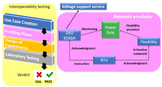
12], the application of the methodology for a DMS UC is performed for the first time at the best of the authors’ knowledge. The selected UC studies an exemplary chain of flexibility activation which provides the Distribution System Operator (DSO) with the voltage regulation service. For accomplishing this voltage support service, the flexibility activation chain is characterized by the following three mutually interacting actors: the Supervisory Control And Data Acquisition system of the DSO (DSO SCADA), a field gateway in the form of a Remote Terminal Unit (RTU) and a flexibility source in terms of a flexible load (FLEX). Using a widely known terminology within the testing community, these three actors can be considered to be building the Equipment Under Test (EUT), since the functionality of the flexibility activation chain as a whole is investigated under an IOP perspective. However, in this research work, no physical hardware implementation is done, instead models of these three actors are employed. A specific test bed is adopted, which includes a testing environment comprising real-time power grid simulator and communication network emulator. The test bed used in this research work is based on a hardware-in-the-loop (HiL) setup.
This research work stems from the SGAM-based interoperability/interchangeability study carried out in the European Union Horizon 2020 InterFlex project [
13], where six different European demonstration sites were realized with a focus on flexibility services, spanning from energy generation to demand. Two findings of [
13] are used in this research work to build the architecture and the functionality of the selected UC, as follows.
In [
13], two main architectures are identified (out of the different European demonstrators implemented therein) which are at disposal for the DSO to activate the flexibility source, namely via a direct (“lower-bound”) or an indirect (“upper-bound”) interface. More specifically, the DSO could either employ its own field gateway (e.g., an RTU) to access the sources of flexibility (lower-bound architecture) or, alternatively, the DSO SCADA system can be first interfaced with an intermediate actor (an aggregator or an energy management system) and then access the flexibility via a field gateway (upper-bound architecture). The reader is referred to [
14] for more details. The first alternative (lower-bound architecture) is employed for building the architecture of the UC selected for this research work, while the second one is not addressed.
In [
13], a set of “super-categories” is identified as a set of possible DSO services supported by the activation of a flexibility chain across the different European demonstrators implemented therein. More details in this regard are provided in [
15]. Out of all the super-categories identified (e.g., congestion management, frequency support, voltage support, etc.), the “voltage support” service is used in this research work for defining the functionality of the selected UC.
In addition, in the present paper, connections with [
13] are made where needed to motivate some specific assumptions and applications. For example, some of the telecommunication technologies considered during the BAP creation or the intervals of variation of some input parameters during the DoE step do reflect some demo-specific implementations of [
13].
In the adopted UC, the lower-bound architecture (employed by the DSO to activate the flexibility source) for providing a voltage support service is analyzed under an IOP point of view. In particular, the performance of the system represented by the chain DSO SCADA ↔ RTU and RTU ↔ FLEX is investigated under different operational conditions (considering, during the DoE phase, heterogeneous parameters, i.e., related to the voltage support service as well as to the communication infrastructure), evaluating their effect on influencing the IOP testing verdict. Specifically, the outcome of IOP testing is defined in terms of a “pass” or “fail” verdict, considering the final value of the restored voltage at a specific power grid node after the flexibility activation. The results lead to a qualitative ranking of the input parameters in terms of relative importance in affecting the system performance.
This approach of IOP testing can be mapped to the so-called “active interoperability testing”, which is the alternative of the “passive interoperability testing”. In [
16], the difference between these two approaches is extensively addressed. The passive IOP testing can be seen as a simple “monitoring” of the EUT to detect possible IOP issues (faults) when the EUT works in normal conditions. On the other hand, the active IOP testing has the scope to detect IOP faults on a given EUT by applying a series of stimuli, hence disturbing the normal EUT operation. Examples of passive IOP tests are more easily found in the literature, being more straightforward and less consuming in terms of testing system deployment. For example, reference [
17] proposes a passive IOP test method for IEC 61850-9-2-based multi-vendor merging units, which exchange information with a protection relay. The IOP testing result is in the form of a “pass” or “fail”. Similarly, paper [
18] performs a passive IOP testing between multi-vendor digital substation devices and the test results are again in the form of IOP success or failure. These are some examples of common practices of passive IOP testing. However, in the research work described in the present paper the active IOP testing approach is chosen, since the interest is in investigating the system IOP under different operational conditions.
It is noteworthy that the methodological approach followed and applied in this research work for IOP testing purposes is not restricted to the specific UC. In particular, the same procedure can be applied not only to the UCs implemented in all the demonstrators of [
13] (which provide a comprehensive and applicative environment for an IOP testing in the SG context), but also to any other set of demonstrators/UCs in the SG domain. Of course, the specific instantiation of the IOP testing methodology has to take into account the peculiar properties of the UC under analysis (e.g., architecture, functionality, etc.) so to design a meaningful and robust IOP testing specifically tailored for the SG application under study. In fact, not only will the definition of BAPs, BAIOPs and DoE be different (depending on the specifics of the developed UC), but also proper modifications and/or extension of the adopted test bed as well as the selected EUT have to be operated when considering different UCs and other (physical or modelled) equipment. Nonetheless, the considerations made in this research work may be useful and reusable in the sense that general directions to take into account when applying this IOP testing approach are provided and highlighted to facilitate specialized engineers and/or SG stakeholders when dealing with the IOP testing challenge.
The main contributions of this research work are as follows.
After being applied to the examined UC, the JRC-SGILab methodology has revealed to be a flexible and valuable tool to successfully accomplish the breakdown of the IOP testing into a structured framework. The broad-scope range of applicability of this methodology is proven to be promising and a variety of different SG applications can undoubtedly benefit from it when tackling the challenge of the IOP testing.
Beside a thorough definition of BAPs and BAIOPs, the experimental design has been found to be a crucial activity to thoroughly characterize complex systems and investigate their performance under an IOP perspective. The systematic laying out of a detailed experimental plan should be an essential step before performing an IOP testing of any SG application.
From the collected results, it is shown that, without the integration (within the IOP testing workflow) of fine statistical tools, it is challenging to deepen specific features of the system IOP behavior (for example, the ranking in quantitative terms of the system parameters or the identification of mutual interactions which may be important in driving the IOP verdict).
The concepts of inter- and intra-BAIOP testing are proposed in this work to reflect different (but possibly complementary) interests of SG stakeholders, i.e., the evaluation of the system IOP across multiple BAIOPs and/or within one specific BAIOP.
From this research work, SG stakeholders can have a useful insight into possible downsides to take into account when they have to deal with the IOP testing challenge in large-scale and complex power systems as well as future SG applications similar to the one addressed with the examined UC.
The rest of the paper is organized as follows.
Section 2 describes the adopted JRC-SGILab methodology, its application to the examined UC for the purpose of IOP testing and the concepts of inter- and intra-BAIOP.
Section 3 provides and comments the experimental results.
Section 4 includes the discussion which can be derived from this research work.
Section 5 provides the conclusions.
3. Results
In this section, the results for both inter-BAIOP and intra-BAIOP tests are illustrated and the respective conclusions are drawn. It is noteworthy that these conclusions are bound to the modelling environment (both grid and component models) and the assumptions used in this UC in order to set the boundaries for the IOP testing.
The following convention is adopted for the plots presented from
Figure 6,
Figure 7,
Figure 8,
Figure 9 and
Figure 10. The values of
(readable on the right axis) are indicated with black diamonds, while the values of
(readable on the left axis) are indicated with vertical bars. The information regarding the IOP verdict is carried by the color of the vertical bars: red and green bars indicate the outcome of “fail” and “pass”, respectively.
3.1. Inter-BAIOP Interoperability Testing
In this subsection, the results of the experiments with respect to the inter-BAIOP IOP testing are provided. The scope of this inter-BAIOP test is to assess what is the influence of selecting different BAIOPs on the system performance under an IOP perspective.
The three experiments for the inter-BAIOP tests lead to the results reported in
Figure 6, where the different possible telecommunication architectures (BAIOPs) considered in
Table 5 are investigated. The performance of the system represented by the flexibility activation chain is examined in terms of
and
values, and the IOP verdict is recorded. From
Figure 6 the following conclusion can be derived.
The three different BAIOPs can equally support the voltage deviation and restore the voltage to = per unit. Evaluating the system response in terms of , the restoration time shows more dependency on the specific telecommunication technology combinations.
The IOP verdict is “pass” in each of the three tested configurations: when the system is placed under non-stress conditions (mean values of the service-related parameters within their intervals of variation), all the three BAIOPs successfully pass the IOP test. Therefore, speaking in terms of IOP verdict, in this situation the system IOP is not affected by the selection of different BAIOPs.
The results deriving from this inter-BAIOP testing can be used, for example, by the DSO in the following manner. Given that all the three BAIOPs successfully pass the IOP test, the attention of the DSO, in order to “rate” the quality of the voltage support service under different telecommunication architectures, may be aimed towards the one which is capable of delivering the optimal combination of and . In this specific case, the BAIOP able to deliver the best (i.e., the least restoration time) would be chosen.
It has to be highlighted that other strategies could be used for this inter-BAIOP testing: for example, instead of using mean values for the service-related parameters in each BAIOP, the sampling of more experimental points might have been an alternative, as well as choosing another inter-BAIOP “indicator” (for evaluating the effect of selecting different BAIOPs) instead of the same system responses used for the intra-BAIOP testing (i.e., and ). The choice of other indicators for evaluating the system performance across BAIOPs is left as future work direction.
3.2. Intra-BAIOP Interoperability Testing
In this subsection, the results of the experiments for the intra-BAIOP tests are shown. The aim of these intra-BAIOP tests is to assess how the system performance (and therefore the IOP verdict) is affected, within a specific BAIOP, when changing the configuration of the service-related parameters (potentially considering also stress conditions).
As described in
Section 2.3.5, intra-BAIOP testing is carried out within a specific telecommunication architecture (i.e., BAIOP, with values of the communication parameters as specified in
Table 4). In particular, the BAIOP which has provided the best results after the inter-BAIOP testing (
Figure 6) is worth investigating (in other words, the information derived from the inter-BAIOP testing can guide the intra-BAIOP testing). In this particular case, it is assumed that the DSO (in order to be able to deliver the “best” quality of service according to its own preference) chooses BAIOP 1, where an optimal combination of restored voltage and restoration time is achieved. For this selected telecommunication architecture, the intra-BAIOP testing provides an insight about the performance of the flexibility activation chain under an IOP point of view, by assessing the system behavior for different configurations of
,
,
and
. In particular, for each BAIOP the N test cases are produced by letting each service-related input factor, one after another, free to vary within its interval of variation while the others are set at their mean values.
3.2.1. DSO-Related Intra-BAIOP Testing
To analyze the impact of the
that the DSO considers for the voltage support service, an intra-BAIOP testing is carried out by setting
,
,
to their mean values while
varies in the tolerance range that the DSO wants to provide for its voltage support service. In particular, the interval of variation defined for
(see
Table 6) is less than the voltage deviation at the node under study caused by the disturbance. A random sampling is performed within the range of variation of
.
The experimental results after running this set of test cases can be observed in
Figure 7.
The following conclusions can be drawn from
Figure 7. The quality of service (
) that the DSO wants to provide after a disturbance can affect the restoration time (
). On the other hand, the amount of restored voltage (
) is not affected at all, since it is dependent on the (fixed) amount of flexibility (
) available at the specific node. Moreover, it can be noticed that, when the flexibility and RTU-related parameters are fixed at their mean value, there is a minimum amount of
required for the system to restore; below this threshold, the IOP test fails (red bars at low values of
). In other words, the DSO cannot expect to increase the quality of service (i.e., decrease
) while the amount of available flexibility at the customer side (
) is fixed.
3.2.2. Flexibility-Related Intra-BAIOP Testing
The impact on the system response of FLEX-related input factors (
and
) is then investigated. For this purpose, the values of
and
are set to the mean value in their variation range (see
Table 6).
First, to analyze the effect of on the system performance, is also set at its mean value, letting free to vary within its range of variation.
As shown in
Figure 8,
has an influence on both
and
, as well as on the IOP verdict. It can be observed that there should be a minimum amount of flexibility to restore the voltage. This aspect needs to be taken into consideration by the DSO while making the contractual agreement with the flexibility owner: if the amount of
is below a certain amount, the IOP test will fail.
Similarly, to analyze the effect of
on the system response,
is now set at its mean value, with
left free to vary. The result can be observed in
Figure 9.
As observed, influences the system response only in terms of the restoration time, the restored voltage value not being affected at all. No “fail” IOP verdicts are recorded in this specific input configuration.
3.2.3. RTU-Related Intra-BAIOP Testing
Finally, the parameters related to DSO (
) and FLEX (
,
) are set to their mean values, while
varies within its predefined range. The results can be observed in
Figure 10.
As observed,
influences the behavior of the system only in terms of the restoration time. Similar to
Figure 9, there are no failure situations with the specific operational conditions.
In addition, by comparing the results of
Figure 9 and
Figure 10 (in terms of
), it can be concluded that
has a higher impact on affecting the restoration time compared to
.
Collecting all the results shown in this subsection for the intra-BAIOP testing (bound to the assumptions made for modelling the UC), the following conclusions can be additionally drawn. For a given BAIOP, when the system represented by the flexibility activation chain is studied for different configurations of the service-related input factors (possibly considering also stress conditions), its performance as well as the IOP verdict are affected in a different manner: some parameters are able to change the IOP verdict, while other ones seem not important in leading the variation of the system IOP outcome. In qualitative terms, it can be concluded that and have a higher importance with respect to and , since they are able (with their variation) to change the IOP verdict from “fail” to “pass”. However, a quantitative ranking (in terms of importance) of the service-related input factors (in accordance to the selected system responses) is challenging.
Moreover, there are minimum values of and (bound to the specific service-related input configuration used for conducting these intra-BAIOP tests) which the DSO needs to take into account for guaranteeing system IOP, and therefore it seems that interactions do exist between these input factors.
Given these considerations, in order to derive conclusions in terms of quantitative ranking of the input factors, quantification of the interactions and “IOP thresholds”, more advanced statistical tools are needed, which might effectively assist the SG stakeholders in getting this type of information.
4. Discussion
In this work, an application of the JRC-SGILab methodology proposed in [
10] is presented for IOP testing within the context of a DMS UC, by using a real-time simulation environment with a CHiL technique. The examined UC describes the flexibility activation chain involving DSO SCADA, RTU and FLEX, mutually interacting to provide the voltage support service.
Given the difficulty of the IOP testing problem, in this research work a lot of attention has been put on the application of methodological aspects formalized in the JRC-SGILab methodology report [
10], namely (1) UC creation, (2) BAP and (3) BAIOP definition, (4) DoE procedure, the latter specifically applied in the UC under study since several parameters can change and affect the system functionality under an IOP point of view. The JRC-SGILab methodology has revealed to be a valuable tool to properly support the breakdown process of the IOP testing problem into a structured framework.
In this research work two types of testing, namely inter- and intra-BAIOP tests, are carried out to evaluate the system performance and IOP across different BAIOPs and within a specific BAIOP, respectively. These two types of IOP testing can be seen as an extension/enhancement of the “testing” activity of the JRC-SGILab methodology [
10], since they can be used in a complementary manner by SG stakeholders when their interest is assessing the system IOP both across the selected BAIOPs (inter-BAIOP IOP testing) and within a specific BAIOP (intra-BAIOP IOP testing). If the concept of intra-BAIOP testing is somehow implicit in [
10], the concept of inter-BAIOP testing is here specified for the first time and can be further investigated. For example, it can be adapted (depending on the UC under analysis) to formalize a UC specific indicator which can effectively assist DSOs and SG stakeholders in general during their decision making process while examining system IOP across different BAIOPs.
It has to be highlighted that the AoE step (involving sensitivity analysis, metamodeling, adaptive strategies) of the JRC-SGILab methodology, even if of high interest for the application of this research work, is not specifically applied to the selected UC. In fact, this research work was originated from the motivation to preliminarily start “setting the scene” of an IOP testing layout of a large-scale and heterogeneous system (i.e., entailing parameters not only related to the power grid but also to the communication), before already performing more advanced statistical analyses, whose effectiveness can be fully recognized in a system with higher maturity level. Nonetheless, this first application of the methodology has made possible revealing some interesting features and potential drawbacks which need to be taken into account when performing IOP testing in UCs and systems similar to those of this research work. These emerged considerations are discussed hereafter and will be guiding the authors in the refinement of the test bed as well as the UC, and the implementation of the AoE procedure in an already known environment.
It is emerged how critical the DoE phase is, beside the BAP-BAIOP specification. In particular, in order to carry out a full characterization of the system under analysis and a thorough IOP testing, much effort needs to be put in the definition of the input factors together with the system response(s) to properly assess the overall system performance, detect possible IOP issues and identify the parameters responsible for driving the IOP verdict. For example, in the performed intra-BAIOP testing four service-related input factors are selected during the DoE phase as being potentially able to influence the system output with their variation, while the communication parameters are fixed in each BAIOP. However, one could make the choice to select different service-related parameters (and/or system outputs), or even to increase their number. In the similar direction, while performing an intra-BAIOP testing the communication-related parameters (in this research work fixed in the intra-BAIOP testing) could also be changed (together with the service-related input factors) to investigate the relative importance of heterogeneous (i.e., service- and communication- related) parameters in jointly driving the system performance. However, while defining the ranges of variation for the communication-related parameters there would be the constraint to specify them such that no violation of the communication requirements of the selected telecommunication architecture (BAIOP) is made. In other words, if their ranges are not defined carefully, the experimenter will run into the risk to consider communication parameters which are not realistic for the specific telecommunication technology under study. Clearly, this aspect is not trivial and needs further investigation of the standards regulating the communication interfaces between the UC actors. Still, as long as the analyst is interested in the investigation of the system IOP across different BAIOPs, the concept of inter-BAIOP testing remains valid as complementary type of test.
Moreover, the choice per se of additional input parameters is not as simple as it may seem at first glance: in fact, it will inevitably result in an increase of the system dimensionality. This feature can be supported only by the deployment of more advanced statistical tools, able to effectively cope with the higher system dimensionality and complexity. One example is the integration of a proper sensitivity analysis (as suggested in [
10]), which can assist the experimenter in (1) quantitatively ranking the input factors according to their importance in driving the IOP verdict, (2) reducing the dimensionality of the system and (3) revealing interactive features between system inputs. In particular, properties (1) and (3) would help in a further investigation, given that in the intra-BAIOP testing performed in this research work the ranking of the input factors and the identification of the interactions between them are possible only in qualitative terms. The authors are aware of the potentiality of this statistical analysis and its application is envisaged in a future work.
Regarding the IOP testing outcome per se, in this research work an evaluation of the IOP verdict in terms of “pass” or “fail” is considered. However, in order to deepen the system IOP investigation, it can be of interest to define an “interoperability boundary”, i.e., to identify the regions in the system input space where the IOP verdict changes from “success” to “failure”. The same consideration done for the system dimensionality increase applies here, i.e., more advanced statistical tools would be required for this purpose.
For what concerns the UC development, the possibility to include (within the class of UCs similar to the one examined in this research work) market-related considerations which are easily mapped to the business SGAM layer has also emerged. For instance, it might be of interest to consider the idea of a DSO-oriented indicator, which can be set according to the DSO preference taking into account variable scores for quantifying the quality of service. In this case, a business-related system output is worth investigating.
Furthermore, the testing environment adopted in this research work provides the foundation for more sophisticated tests in which DSOs and flexibility providers can assess the IOP of the different actors in achieving the service objectives by: (1) refining the test bed by the inclusion of the indirect flexibility activation mechanism (upper-bound architecture) via a market platform (through aggregators) or via an energy management system considering operational and economical objectives; (2) modification of the test bed to include hardware equipment (PHiL tests including real power hardware components such as storage units, photovoltaic inverter, etc.); (3) combination of (1) and (2).
In short, extension of the analyses in the direction of the statistical AoE, refinement of the maturity level of the testing environment and application of a more detailed DoE procedure are envisaged by the authors as future work.


