Article

Study on the Tri-axial Time-Dependent Deformation and Constitutive Model of Glauberite Salt Rock under the Coupled Effects of Compression and Dissolution

1
College of Mining Engineering, Taiyuan University of Technology, Taiyuan 030000, China
2
Key Laboratory of In-Situ Modified Mining of Ministry of Education, Taiyuan University of Technology, Taiyuan 030000, China
3
Department of Civil and Environmental Engineering, University of Waterloo, Waterloo, ON 50701, Canada
*
Author to whom correspondence should be addressed.
Energies 2020, 13(7), 1797; https://doi.org/10.3390/en13071797
Submission received: 22 January 2020 / Revised: 25 March 2020 / Accepted: 28 March 2020 / Published: 8 April 2020
(This article belongs to the Section B: Energy and Environment)

Abstract

:
Solution mining for glauberite salt rock is a long-term process that takes several years to several decades. Therefore, deposit deformations and subsidence of ground surfaces are time-dependent deformation problems that should consider the effect of water dissolution. In order to investigate the time-dependent deformation characteristics of glauberite salt rock, tri-axial time-dependent deformation tests were conducted under the condition of 4 MPa confining pressure and 5 MPa axial pressure with infiltration pressures of 3, 2, 1, and 0 MPa, respectively, and the micro-CT scan system was used to scan the glauberite specimens before and after the experiment in order to study the fracture evolution inside the specimen, and a damage constitutive model was established to fit the time-dependent deformation curves based on the damage mechanics and effective stress principle. To simulate the solution mining process, the time-dependent deformation process of glauberite salt rock was divided into three stages: hydraulic connection stage, water-saturated stage, and drainage stage. The results demonstrate that the hydraulic connection time for glauberite salt rock decreases with increasing infiltration pressure. The time-dependent deformations of the specimens at the hydraulic connection and saturated-water stages are significantly affected by the effective stress and continual mineral dissolution. At the drainage stage, the softening degree of the solid skeleton mechanical properties, which is caused by the dissolution effect and infiltration pressure loading history, decides the deformation of glauberite salt rock. In addition, the degree of softening inside glauberite salt rock caused by dissolution becomes more severe with increasing infiltration pressure using the micro-CT scan technology. Lastly, the time-dependent damage constitutive model is able to describe the tri-axial time-dependent deformation behavior of glauberite salt rock, and the variations of time-dependent deformation parameters further indicate the damage evolution of the solid skeleton mechanical properties of glauberite caused by infiltration pressure and dissolution effect.

1. Introduction

Glauberite is an unusual salt rock that mainly consists of sodium sulfate and calcium sulfate, i.e., Na2Ca(SO4)2 (anhydrous sodium calcium sulfate), in an anhydrous state [1]. Sodium sulfate is highly soluble in water with the solubility of 192.32 g per liter of water at saturation (20 °C), while calcium sulfate has a low water solubility with 2.02 g per liter of water at saturation (20 °C) [2]. Sodium sulfate, an important raw material in the chemical industry, can be extracted from glauberite deposits using solution mining technologies [3]. Solution mining, commonly used in salt fields, involves drilling wells to subsurface ores and dissolving the ore to obtain the minerals by injecting fresh water and pumping the salt solution to the surface [4]. The solution mining method has been reported to be safer and more economical compared to conventional underground mining. Solution mining is a long process of ore body dissolution that takes several years to decades. Based on the principle of effective stress, subtracting the total stress to pore water pressure gives the effective stress. Consequently, during this process, ore bodies are subjected to mineral dissolution and dynamic effective stress changes, and time-dependent behaviors of ore bodies occur with the gradual evolution of the pore structure. The progress of dissolution of the ore bodies affects the production efficiency of solution mining, and the time-dependent dissolution process also triggers deformations and fractures of ore bodies and the subsequent surface subsidence [5,6]. For the long-term stability assessment of solution mining, it is essential to understand the time-dependent behaviors of glauberite salt rock.
The time-dependent properties of salt rock are of fundamental importance in predicting long-term evolution of strategic storage caverns for oil and gas and as well as nuclear waste disposal in China due to their characteristics of low permeability and porosity [7,8]. As salt rock exhibits pronounced creep characteristics even under relatively low loads, many efforts have been devoted to investigating the mechanical creep behavior of salt rock through laboratory experiments and theories [9,10,11,12,13,14,15]. Creep test is the direct method to research the creep properties of salt rock, and it has been adopted by scholars to observe the creep deformation and rock characteristics. References [13,14] analyzed the influence of confining pressure on the creep properties based on larger amounts of uniaxial and tri-axial experimental data. The author of [16] compared and analyzed the creep deformation of glauberite, anhydrite, and argillaceous salt rock based on tri-axial creep test. Considering the factor of temperature effect, [17] found that temperature strongly influences the creep properties of salt. To better understand the creep mechanism and predict the long-term deformation and stability of salt caverns, lots of constitutive equations have been established and proposed. The authors of [18] built a new elastic/viscoplastic transient creep model according to the true tri-axial test results. Reference [19] proposed an improved Kelvin–Hooke model to precisely describe the creep behavior of thenardite, while [20] established the creep model to investigate the time-dependent behavior of salt based on fractional calculus.
Particularly, in the process of solution mining from glauberite ore, original impermeable glauberite gradually evolves into a porous medium because dissolution of glauberite leads to removal of sodium sulfate in solution and precipitation of gypsum (CaSO4.2H2O) or anhydrite (CaSO4) depending on total solution composition and temperature. The authors of [3] studied the evolution characteristics of pores and residual porous skeleton of glauberite dissolved in fresh water using the micro-computed tomography. Reference [21] studied the microstructure development of glauberite under the influence of chemistry and temperature, while [1] investigated the chemical dissolution and seepage characteristics of glauberite salt rock. As the evolving porous medium is generated, it results in the variation of all the mechanical properties with interior structure alteration, such as strength, deformation moduli, and acoustic velocity.
In addition, pressure solution also plays an important role in the deformation mechanism [22] of time-dependent deformation with the presence of saturated solution [2]. It involves the dissolution of grains at highly stressed boundaries, diffusion of material through the grain boundary fluid or fluid-filled channel network, and crystallization of material at interfaces under low normal stress. These three transport steps occur in series, and the slowest controls the rate of creep [23,24,25,26]. Due to the coupled effects of a continuously evolving solid skeleton and pore water pressure, the time-dependent characteristics of glauberite salt rock are very unusual. Consequently, the dissolution and erosion effects of water need to be considered when investigating the time-dependent characteristics of glauberite salt rock, which has theoretical and practical engineering significance.
These previous studies mentioned above covered the mechanical characteristics of creep in salt rock that are influenced by various loading conditions (axial pressure, confining pressure, and loading rate) and temperatures. However, up to now, little research has been conducted on the time-dependent deformation of salt rock that is coupled to the hydraulic phenomenon under tri-axial stress conditions [26,27,28], especially for glauberite salt rock.
In this paper, to investigate the time-dependent deformation characteristics of glauberite salt rock under the combined compression and dissolution effects, tri-axial time-dependent deformation tests were conducted on glauberite salt rock with three different infiltration pressures. These tests consisted of three stages in sequence: hydraulic connection stage, water-saturated stage, and drainage stage. Based on the concept of damage mechanics and effective stress principle to the generalized Kelvin model, a time-dependent damage constitutive model was proposed to explain the results from these laboratory tests. These experimental and theoretical studies are expected to provide a reference for analyzing cavern stability and surface subsidence in solution mining.

2. Materials and Methods

2.1. Preparation of Specimen for Tri-axial Compression Test

The tested glauberite salt rock samples were from a glauberite deposit approximately 200 m underground located in Pengshan, Sichuan Province, China. The irregular original glauberite samples were blasted and transported to the laboratory of Taiyuan University of Technology; then, four standard column specimens with dimensions of Φ50 × 100 mm (Figure 1) were formed from these samples. The physical and mechanical properties of glauberite salt rock are shown in Table 1. In the glauberite specimens, the contents of sodium sulfate (Na2SO4) and calcium sulfate (CaSO4) are 40 wt% and 35 wt%, respectively. As shown in Table 2, the main components of the tested glauberite samples are glauberite (anhydrous sodium calcium sulfate), quartz, chlorite, mica, montmorillonite, and illite [21].

2.2. Microstructural Observation of Glauberite

Microstructure analysis was carried out by means of optical microscopy performed on thin and ultra-thin sections of epoxy-impregnated samples. Examination of the material showed that the glauberite minerals exist as granular plate-shaped texture with the grain size mostly between 0.5 mm and 2 mm, and they are distributed non-uniformly in the sample (Figure 2). In addition, the observation of crystal boundary structure and crystal size distribution was done by reflected light- and scanning electron microscopy (SEM), and the glauberite sample’s surface was carefully ground and polished before the examination. Figure 3 shows the shape and size of glauberite crystals, with different scale bars, obtained in the sample.

2.3. Testing Apparatus

2.3.1. Tri-axial Apparatus

As shown in Figure 4, the main apparatus used for this test is the tri-axial apparatus in the Key Laboratory of In-Situ Modified Mining of Ministry of Education at Taiyuan University of Technology, and the rock specimen with 50 mm diameter and 100 mm height was enclosed in a rubber sealing jacket between porous discs at top and bottom of the specimen. The confining pressure was provided in the cell pressure to cause three-dimensional deformation of the rock specimen, with the precision of 0.01 MPa. The axial load was applied through the loading ram, keeping the loading constant with the precision of 0.01 KN. The pore water pressure was applied on the bottom of the specimen through the porous disc, and the water escaped at the top through the whole length of the specimen.

2.3.2. X-ray Micro-Computed Tomography (μCT)

The micro-CT scan system at Taiyuan University of Technology [30,31] was used to scan all the glauberite specimens before and after the experiment, and the scans were conducted with 400 frames and a superimposed frame rate of 2 fps, and there were 1500 scanned layers. In this experiment, the parameters used in the CT procedure were the scanning voltage and electric current, which were 70 Kv and 90 μA, respectively. The magnification was 7.2 times, and the middle layer of the specimen was selected to analyze the evolution of fractures inside the specimens under the coupled effects of compression and dissolution.

2.4. Experimental Methodology

To investigate the long-term behavior of glauberite salt rock under the coupled effect of stress and dissolution, three infiltration pressures were tested with the same axial and confining pressures as shown in Table 3. The axial pressure and circular confining pressure loaded on the column specimens were 5.0 and 4.0 MPa, respectively. The infiltration pressures loaded on the bottom of the specimens with fresh water were 3.0, 2.0, 1.0 and 0 MPa, and the specimen with 0 MPa was a dry control experiment, which can be regarded as an example of time-dependent deformation characteristics without infiltration pressure. In addition, the micro-CT scan system was used to scan the glauberite specimens before and after the experiment in order to study the fracture evolution inside the specimen.
Under the designed compression and infiltration pressure, the time required for pore and fissure coalescence in the specimen was recorded along with the axial deformation. During the time-dependent deformation experiments, the axial deformations of the specimens were recorded every half hour using a dial gauge with a resolution of 1 ‰ mm, and the data were automatically collected and recorded by a computer. The procedures of the experiment were to (1) apply the designed axial stress and confining pressure on the specimen; (2) apply the infiltration pressure on the bottom end of specimen and record the axial deformation as zero simultaneously; (3) keep the pore pressure outlet closed when there was water flow from the outlet. This process is the hydraulic connection stage; (4) keep the state constant until 500 h. This process is the water-saturated stage; (5) unload the water pressure until 720 h. This process is the drainage stage.
The reason for dividing this experiment into three stages is to model the in-situ solution mining process of glauberite ore. The hydraulic connection stage is the process where water is injected from an injection well into the glauberite deposit, but there is no hydraulic connected channel between the injection well and the production well; this is called the water-saturated stage after the hydraulic connection channel is created. The difference between the two previous stages is that the water-saturated stage has hydraulic connected channels in the glauberite ore, which indicates that the glauberite is in a water-saturated state. The drainage stage is to investigate the time-dependent deformation of glauberite after solution mining.

3. Results

3.1. Time-Dependent Deformation During Loading

Figure 5 shows the strain evolution of specimens 0, 1, 2, and 3 over time during the entire experiment. Within the figures, the letters represent different stages in the time-dependent experiments: “a” denotes hydraulic connection stage; “b” and “c” represent the water-saturated stage and drainage stage, respectively. The numbers of “1”, “2”, and “3” in “a-1”, “b-1”, “b-2”, etc., are specimens 1, 2, and 3, respectively.
In these tests, specimen 1 was not hydraulically connected; therefore, it did not experience the water-saturated stage, unlike specimens 2 and 3. Figure 5 shows that the deformations of specimens 0, 1, 2, and 3 generally increased with time during different stages. However, the degree of weakening of glauberite salt rock under the dissolution and erosion effects and the effective stress varied with different infiltration pressures, indicating obvious difference in the deformation mechanisms and characteristics of specimens 1, 2, and 3 at different stages. Comparing the time-dependent deformations of specimens 1, 2, and 3 with that of specimen 0, it is obvious that infiltration pressure causes degradation of mechanical properties of the glauberite specimen. At the hydraulic connection stage and water-saturated stage, the time-dependent deformations of the specimens were dominated by the effective stress and the degree of weakening of the solid skeleton caused by the dissolution effect. In addition, at the drainage stage, the time-dependent deformations of specimens 1, 2, and 3 were greater compared to previous stage for the same amount of time.

3.2. Time-Dependent Deformation During the Hydraulic Connection Stage

Figure 6 shows the time-dependent deformation strain of specimens 2 and 3 over time for infiltration pressures of 2.0 and 3.0 MPa, respectively. It indicates that the two specimens have different time-dependent properties with different infiltration pressures. For specimen 3 with a dissolution and infiltration pressure of 3 MPa, a sharp increase in strain occurred during the time-dependent test even though the strain was small. The axial strain of the specimen increased from 0.12% to 0.135% until the cylinder specimen was hydraulically connected from the bottom to the top face. This behavior showed the gradual softening process of glauberite during the dissolution of the dissolvable components. The original glauberite was intact and hard; however, as the dissolvable components were dissolved with high infiltration pressure, even though this dissolution may be trivial, the glauberite gradually became porous and soft with cohesion decreased. The original solid and stable structure quickly collapsed when this softening accumulated to a certain level. The picture of specimen 3 in Figure 1b after infiltration shows that the deformation mainly occurred at the bottom part where the dissolution and softening effects are stronger. The water dissolution and softening effects vary along the specimen during the infiltration and dissolution process; these effects are obviously stronger at the bottom than at the top of the specimen even at a 3 MPa infiltration pressure. This result indicates that high infiltration pressures and long dissolution times are needed to increase the recovery of the mineral components from glauberite salt rock.
For specimen 2, the infiltration pressure was 1 MPa lower than that of specimen 3. The time-dependent deformation strain of specimen 2 gradually increased to 0.127% in 137.5 h, and it sharply increased to 0.137% before the specimen was hydraulically connected. Compared with the 0.135% strain of specimen 3, the strain of specimen 2 was approximately the same as that of specimen 1, but the time needed for specimen 2 was 53 h more than that for specimen 3. This difference in deformation between the two specimens reflects the effect of the infiltration pressure on the behavior of glauberite. This effect of the infiltration pressure is also shown in the time required to become hydraulically connected for the two specimens. At a 3 MPa infiltration pressure, specimen 3 became hydraulically connected after 84.5 h; at a 2 MPa infiltration pressure, specimen 2 required an additional 53 h.
The infiltration pressure for specimen 1 was 1 MPa, which was lower than that of both specimens 2 and 3. At this low pressure, specimen 1 was not hydraulically connected during the 500 h at the design tri-axial stress and infiltration pressure. The strain gradually increased to 0.108% in 350 h and then remained approximately constant from 350 to 500 h (Figure 6b). Compared with the strains of specimens 2 and 3, the strains of specimens 1 and 0 were much smaller in the same time (in 140 h). Thus, the infiltration pressure and dissolution time greatly affect the water seepage and mineral dissolution inside the glauberite. Higher injection and infiltration pressures seem favorable for hydraulic coalescence of glauberite in a larger domain during solution recovery.

3.3. Time-Dependent Deformation at the Saturated-Water Stage

Specimens 2 and 3 were exposed to infiltration pressures of 2 and 3 MPa, respectively, resulting in small effective stresses on the solid skeleton of the two specimens. For specimen 3 with a uniform pore distribution, the effective stress on the solid skeleton was 1–2 MPa when the specimen was subjected to a pore pressure of 3 MPa. Under the tri-axial stress state, little deformation and failure occurred for specimen 3. As a result, the axial strain gradually increased to 0.137% from 0.169% over 414 h, and the strain increment was 0.032%, as shown in Figure 7. As previously mentioned, a distinct difference was shown in the degree of softening and the deformation of the specimen as a result of the difference in the dissolution time. Since the bottom of the specimen experiences dissolution for a longer time, the pores were relatively better developed in this area, and the degree of softening by dissolution reaction was greater. In contrast, at the top of a specimen, the pores were poorly developed due to the shorter dissolution time, and the degree of softening due to the dissolution reaction was weaker. Therefore, the difference in porosity caused by water dissolution and erosion directly led to differences in the effective stress on the solid skeleton of the glauberite. The top part of the specimens had undeveloped pores and small or nonexistent pore pressure; in addition, the effective stress on the solid skeleton was smaller. Consequently, the combined effect of the effective stress and the solid skeleton characteristics was prone to producing deformation or shear failure.
The time-dependent deformation strain of specimen 2 increased from 0.137% to 0.179% in 361 h; the increment was 0.042%, which was larger than the strain of 0.032% for specimen 3. The infiltration pressure on specimen 2 was 1 MPa less than that on specimen 1; therefore, at the bottom of specimen 2, the pores caused by water dissolution and erosion were smaller, and the degree of internal deterioration was relatively low. However, the effective stress on specimen 2 was larger than that on specimen 3, resulting in the closure of pores inside the specimen and deformation of the solid skeleton. Consequently, as shown in Figure 6, the strain of specimen 2 over time clearly reflects the time-dependent deformation characteristic. This figure shows that the deformations of the two specimens at this stage are by the axial effective stress on the solid skeleton of glauberite specimens, as well as the dissolution and softening effects.

3.4. Time-Dependent Deformation at the Drainage Stage

Figure 8 shows the strain of specimens 1, 2, 3 respectively, over time at the design tri-axial stress after unloading the infiltration pressure. The time-dependent deformation strain of specimen 1 increased from 0.108% to 0.118%, and its strain increment was 0.01%; the time-dependent deformation strain of specimen 2 increased from 0.179% to 0.206%, and its strain increment was 0.026%, which is 260% of the strain increment of specimen 1. The time-dependent deformation strain of specimen 3 increased from 0.169% to 0.218%, and its strain increment was 0.048%, which is 480% of that of specimen 1. Contrasting the strain increments of specimens 1, 2, and 3 at this stage clearly reflects the important influence of the loading effect at the previous stage on the internal structures of the three specimens. After removing the infiltration pressure, the pore water pressure inside specimens 1, 2, and 3 decreased to 0 MPa, the axial effective stress increased to 5 MPa, and the effects of the pore water pressure and dissolution and erosion on the specimen vanished. Therefore, the three specimens changed from a state of tri-axial stress and infiltration pressure to a tri-axial stress state only.

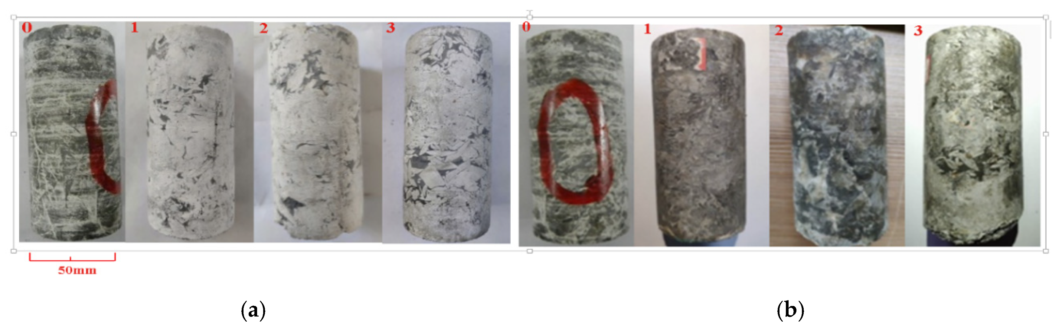
3.5. Analysis of the Fractures before and after the Experiment

Figure 9 shows the 750th layer’s CT scanned cross-section graph of the specimens 1, 2, and 3 before and after the experiment. The gray levels represent materials with different densities in these images, and the black parts are the pores and fractures. It can be clearly seen that the connected fractures of all the specimens after the experiment all increase compared to that before the experiment, which indicates that the glauberite salt rock gradually turns to a porous medium from an intact rock under the condition of pore water pressure. Furthermore, the lengths and apertures of the fractures increase with the increase of pore water pressure, which verifies that the softening degree caused by the dissolution increases with larger infiltration pressure.
The code compiled by MATLAB [31] was used to reprocess the rebuilt CT images and obtain the porosity. Table 4 shows the porosity and weight of glauberite specimens after versus before testing; it can be seen that the porosity of glauberite specimens increase after testing versus before testing, while the weight of glauberite specimens decreases after testing compared to that before testing. In addition, the porosity and weight loss of glauberite specimens with higher infiltration pressure is larger.

4. Discussion

4.1. Time-Dependent Deformation Mechanism of Glauberite Salt Rock under the Coupled Effects of Compression and Dissolution

For glauberite salt rock that is moderately soluble in water, the effect of water on rock should consider not only the effective stress principle but also the chemical effects of dissolution, pressure solution, and hydration of the Ca component of glauberite to form gypsum. When eroded by water, the internal structures of glauberite salt rock undergo a variety of changes, such as the disintegration and swelling of illite and montmorillonite by absorbing water, the dissolution of the sodium sulfate, and the hydration of calcium sulfate. Therefore, under the combined effect of these factors, the mechanical properties of glauberite salt rock decrease, and infiltration pressure reinforces this decrease effect. When saturated by high infiltration pressure over a long period of time, the mutual reinforcing of dissolution and seepage cause all or some of the sodium sulfate to dissolve and a larger number of pores to emerge between the solid matrix of calcium sulfate. In this way, glauberite salt rock changes from a dense rock with low permeability to a porous medium with a main solid skeleton of a calcium sulfate matrix; in addition, its mineral components and structures vary, resulting in varying mechanical properties of glauberite salt rock [1]. Furthermore, compression of the solid skeleton in a tri-axial stress state causes closure of pores, decreasing the permeability [32]. As a consequence, the time-dependent deformations of the specimens are caused by the coupled effects of compression and dissolution.
The infiltration pressure has two important influences on the tri-axial time-dependent deformation of glauberite salt rock. First, the infiltration pressure increases the speed of dissolution and seepage, increasing the amount and size of pores and cracks in the specimen, greatly decreasing the mechanical properties, and increasing the deformation of glauberite salt rock. On the other hand, increasing infiltration pressure constrains the deformation of glauberite salt rock, as the effective stress on the specimen decreases. Therefore, the pore water pressure and deformation of glauberite salt rock not only enhance and accelerate each other but also inhibit each other. The time-dependent deformation mechanism of glauberite salt rock under tri-axial stress and infiltration pressure differs from that of rocks that are not soluble.
The effective stress loaded on a specimen determines the axial deformation of glauberite salt rock. Varying infiltration pressure not only results in different effective stresses on the solid skeleton of glauberite rock but also causes distinctions in the internal components and the microstructure evolution law, such as pores and cracks, that can affect the time-dependent deformation of glauberite rock. The effective stress mainly influences the time-dependent deformations in the following two aspects. First, at saturated pore pressure stage, for the same specimen, the effective stress varies at different stages, leading to ununiform deformations of glauberite salt rock. Thus, the time-dependent deformation behavior is more obvious with larger effective stress. Second, at the water-saturated stage, when the effective stress loaded on the specimen is sufficiently small, the deformation may be small or nonexistent; conversely, the deformation can increase over time with larger effective stress, which can overcome the confining pressure effect. This result is also shown in the deformation differences of specimens 2 and 3. In the solution mining process, initially, applied infiltration pressure results in the decrease of the effective stress of glauberite salt rock, and therefore, the ore body deformations are relatively small. However, ore body deformation increases sharply after the infiltration pressure returns to 0, and the effective stress increases greatly, causing ground surface subsidence. Furthermore, the loading history of the previous stage also has an important effect on the time-dependent deformation of glauberite salt rock [32]. The parameters of the previous stage, such as loading time, the internal structure differences under infiltration pressure, and the dissolution effect, greatly influence the experimental results of the next stage. Comparing the results at the drainage stage clearly shows that the degree of softening of the solid skeleton caused by the infiltration pressure loading history dominates the time-dependent deformation. Generally, the degree of weakening of the solid skeleton is more serious with larger dissolution and infiltration pressure; at this state, the time-dependent deformation strain and the average time-dependent deformation rate are relatively large at the same stress.
The influence of the solution concentration on the time-dependent deformation properties was not considered in this experiment because the fresh water used for the infiltration pressure was changed regularly to ensure that the solution concentration did not reach the saturation point. However, because solute concentration gradients must have existed in the samples, the solution was likely saturated or near-saturated at many points in the sample. While only fresh water was injected, the concentration of dissolved fluid varied spatially and temporally within each sample, depending on fluid pressure gradient, flow rate, and damage development; therefore, in the experiments, the output concentration of the fluid during the saturation stage was measured by a sodium-specific ion meter, and the results are shown in Figure 10. From the figure, it can be seen that during the experiment the solute concentration did not reach the saturation point.

4.2. Constitutive Model Development and Parameter Identification

The generated laboratory results make the development of a constitutive model for glauberite salt rock possible. Several conclusions can be obtained by analyzing the time-dependent deformation curves of the different stages for glauberite salt rock. First, the model should contain an elastic element because glauberite salt rock produces transient elastic strain after loading; then, a viscous element is needed for this model to account for the increasing strain over time. Glauberite salt rock affected by the compression and dissolution shows obvious viscoelastic properties. Because the generalized Kelvin model can describe the viscoelastic characteristics of rocks and it only has three elements that can be easily obtained, this model is used to fit the strain curves of the different stages for glauberite salt rock.
For a single contractive condition, the generalized Kelvin model is composed of one Hooke element and one Kelvin element, and the generalized Kelvin model is shown in Figure 11.
As mentioned before, during the dissolution process of the glauberite salt rock, the mechanical parameters weaken with time due to the gradual increase of the pores and cracks inside the salt rock [1,33]. Therefore, based on the damage mechanics [34], we can propose a damage variable that can denote how the time-dependent deformation parameters evolve with time during the coupled effect of compression and dissolution. Damage variable D can be given as [19]
D = 1 e α t
where   t is the time, and a is a constant that denotes how the damage law changes with time, and the larger the damage function, the larger the α parameter. In order to take into account the influence of damage evolution on the creep behavior, the following expression of elastic modulus E1 (p,D) and E2 (p,D) and viscosity η(p,D) were proposed:
{ E 1 ( p , D ) = E 1 ( p ) · ( 1 D ) E 2 ( p , D ) = E 2 ( p ) · ( 1 D ) η ( p , D ) = η ( p ) · ( 1 D )
where E1(p) is the elastic modulus at the infiltration pressure p and E2(p) and η(p) are the elastic modulus and viscosity coefficient of the Kelvin model, respectively.
To take into account of infiltration pressure effect on the transient creep strain, the constitutive equation of the Hooke model in one dimension is given by
ε 1 = σ 0 E 1 ( p , D ) = σ 0 E 1 ( p ) · ( 1 D ) = σ 0 E 1 ( p ) e α t
where σ 0 is the initial stress.
For the Kelvin model, the relation of stress and strain is
ε 2 + E 2 ( p ) η ( p ) ε 2 = σ 0 η ( p ) e α t
On the basis of the solution method of first-order nonlinear differential equations and the initial condition ε 2 ( t ) = 0 | t = 0 , the general solution of Equation (4) can be obtained as
ε 2 = σ 0 α η ( p ) + E 2 ( p ) ( e α t e E 2 η t )
The total strain is combined with the following two parts:
ε ( t ) = ε 1 + ε 2 = σ 0 E 1 ( p ) e α t + σ 0 α η ( p ) + E 2 ( p ) ( e α t e E 2 η t )
It should be noted that tri-axial stress state should be considered in true rock engineering, so we need get the creep equation in the three dimensions. In the three dimensional stress state, the stress tensor σ i j can be decomposed to deviatoric stress tensor S i j and spherical stress tensor σ m , and the strain tensor can be decomposed to deviatoric strain tensor e i j and spherical strain tensor e m [35]. The relationship between these tensors can be written as
{ σ i j = S i j + δ i j σ m ε i j = e i j + δ i j ε m
in which δ i j is Kronecker function, i ,   j = 1 ,   2 ,   3 , and spherical stress tensor σ m and spherical strain tensor e m can be given by
{ σ m = 1 3 ( σ 1 + σ 2 + σ 3 ) = 1 3 σ i i ε m = 1 3 ( ε 1 + ε 2 + ε 3 ) = 1 3 ε i i
Generally speaking, the spherical stress tensor can only lead to the variation of the bulk of the material, while the deviatoric stress tensor can only change its shape. According to the generalized Hooke law, we obtain the relationship between elastic mechanics parameters of the elastic element on the tri-axial stress state,
{ S i j = 2 G e i j σ m = 3 K ε m
where G is shear modulus and K means bulk modulus.
Substituting Equations (7)–(9) into Equation (6), the creep damage constitutive equation in the three dimensional stress state can be expressed as
ε i j ( t ) = σ m 3 K ( p ) + S i j 2 G 1 ( p ) e α t + S i j α η ( p ) + 2 G 2 ( p ) ( e α t e G 2 ( p ) η ( p ) t )
where G1 is the viscoelastic shear modulus of the Hooke model at the infiltration pressure p, and G2 and η are viscoelastic shear modulus and viscosity shear coefficient of the Kelvin model, respectively.
In addition, effective stress is the important factor that actually determines the mechanical and hydraulic properties of porous rock and soil materials. According to the effective stress principle, the effective stress σ is equal to total stress σ minus pore water pressure p and can be written as [36]
σ = σ p
Substituting Equations (7) and (8) and (11) into Equation (10), we obtain the tri-axial creep damage constitutive equation considering the coupled effect of compression and dissolution
ε i j ( t ) = σ m δ i j p 3 K ( p ) + S i j 2 G 1 ( p ) e α t + S i j α η ( p ) + 2 G 2 ( p ) ( e α t e G 2 ( p ) η ( p ) t )
In this paper, based on the experimental condition for the cylindrical specimen, the minor principle stress and intermediate stress has the same value
σ 2 = σ 3
The axial creep damage constitutive equation can be simplified to
ε 1 ( t ) = σ 1 + 2 σ 3 3 p 9 K ( p ) + 2 ( σ 1 σ 3 ) 3 1 2 G 1 ( p ) e α t + 2 ( σ 1 σ 3 ) 3 1 α η ( p ) + 2 G 2 ( p ) ( e α t e G 2 ( p ) η ( p ) t )
In this test, the elastic deformation was not taken into account in order to precisely simulate the deformation of glauberite deposits during solution mining, so we have
ε 1 ( t ) = 0 | t = 0
Therefore, in this paper, the axial damage constitutive equation can be converted to
ε 1 ( t ) = 2 ( σ 1 σ 3 ) 3 1 α η ( p ) + 2 G 2 ( p ) ( e α t e G 2 ( p ) η ( p ) t )
In this model, not only was the effective stress principle taken into consideration, but the dissolution effect caused by the infiltration pressure was also added.
The time-dependent deformation damage constitutive model was adopted to fit the time-dependent deformation strain curves, and the parameters of this model were obtained using the Levenberg–Marquardt algorithm [37]. It should be noted that in this part, we only used our model to fit experimental data at the hydraulic connection stage and saturated-water stage, not including the drainage stage. The model parameters are shown in Table 5, and the experimental data and time-dependent deformation damage constitutive model for the strain-time curves are shown in Figure 12. The results show that the correlation coefficients of the two results are greater than 0.95, illustrating good fit. Therefore, the time-dependent deformation damage constitutive model can depict the time-dependent deformation characteristics of glauberite salt rock under the coupled effects of compression and dissolution.
Table 5 shows that viscoelastic shear modulus G2 and viscosity shear coefficient η of glauberite decrease over increasing infiltration pressure when the specimens are affected by the dissolution and erosion effects, while the parameter a increases with increasing infiltration pressure, indicating more damage of mechanical properties of glauberite with higher infiltration pressure. The parameter changes further demonstrate the damage degree of the solid skeleton mechanical properties of glauberite caused by infiltration pressure and dissolution effect. Through the careful analysis, the variation process of these three parameters over infiltration pressure can be described respectively, with Equations (17)–(19).
G 2 = 423.09 e p / 0.66 + 231.50       ( R 2 = 0.98 )
η = 26474.01 e 0.53 p       ( R 2 = 0.91 )
α = 0.0005244 ln ( p + 0.2919 )       ( R 2 = 0.95 )
where G2 and p are in the unit of MPa, and η is in the unit of MPa*h, and α is a dimensionless number.
Figure 13 shows the comparison of fitting curve and inversion data of corresponding parameters; it can be seen that the equation basically reflects the evolution of parameters α, G2, and η with infiltration pressure. Substituting Equations (17)–(19) into Equation (16), we can finally establish the time-dependent deformation model for the glauberite, with its axial time-dependent deformation equation as follows
ε 1 ( t ) = 2 ( σ 1 σ 3 ) 3 1 0.1388 ln ( p + 0.2919 ) × e 0.53 p + 846.18 e p / 0.66 ) × ( e 0.0005244 ln ( p + 0.2919 ) t e 0.032 e 0.985 p t )
The damage constitutive model takes into account the damage process of time-dependent (creep) mechanical parameters of glauberite caused by infiltration pressure, which can provide a reference for predicting the time-dependent deformation of glauberite ore during the mining of rough solution.
It should be noted that the constitutive model is a fit to experimental data obtained under specific boundary conditions of fluid injection (0, 1, 2, 3 MPa) and applied stress (σ1 = 5 MPa, σ3 = 4 MPa). Moreover, there are some limitations to this constitutive model. A truly general model should account for the full coupling of fluid flow, mineral dissolution, diffusion and precipitation, porosity evolution, and compression.

5. Conclusions

Cylindrical samples of glauberite salt rock were deformed in 30 days under the conditions of an axial pressure of 5 MPa and a confining pressure of 4 MPa and infiltration pressures in the range of 0–3 MPa. The aim of the experiments was to investigate the time-dependent deformation of glauberite salt rock within three stages, hydraulic connection stage, water-saturated stage, and drainage stage, and this study is expected to provide some guidance on the prediction and assessment of surface subsidence during the process of in-situ solution mining for glauberite ore. Some conclusions can be made based on the results presented in this paper.
During the hydraulic connection stage, the level of infiltration pressure greatly affects differences in the hydraulic connection of glauberite salt rock, and the higher infiltration pressure gives rise to the shorter hydraulic connection time. For specimen 3 to which an infiltration pressure of 3 MPa was applied, it took 84.5 h to become hydraulically connected, which was 53 h shorter than specimen 2 with an infiltration pressure of 2 MPa. With an infiltration pressure of 1 MPa, specimen 1 was not hydraulically connected in 500 h.
During the hydraulic connection stage and water-saturated stage, it is mainly the effective stress and the degree of weakening (caused by the dissolution and erosion effects) that determine the time-dependent deformation of glauberite salt rock. At the hydraulic connection stage, it seems that the degree of weakening of glauberite salt rock dominates the time-dependent deformation. Conversely, for the water-saturated stage, the higher effective stress loaded on the solid skeleton of the glauberite salt rock brings larger time-dependent deformation.
At the drainage stage, the loading history (time, infiltration pressure, etc.) of the previous stage impacts the time-dependent deformation of glauberite salt rock. The larger the infiltration pressure applied on the specimen was, the more pores and fractures developed in the glauberite salt rock, which brings larger time-dependent deformation.
For the specimen loaded with higher infiltration pressure, the lengths and apertures of the fractures and porosity of glauberite salt rock were larger, which further verifies that the softening degree caused by the dissolution increases with larger infiltration pressure. Considering damage law of creep mechanical parameters induced by the infiltration pressure, the damage constitutive model was proposed and used to fit the time-dependent deformation strain curves, and this model can describe the time-dependent deformation of glauberite salt rock under the coupled effects of compression and infiltration pressure.

Author Contributions

Conceptualization, M.C.; methodology, M.C.; software, M.C.; validation, M.C.; formal analysis, M.C.; investigation, M.C.; resources, M.C.; data curation, M.C.; writing—original draft preparation, M.C.; writing—review and editing, S.Y. All authors have read and agreed to the published version of the manuscript.

Funding

This research was funded by the National Science Fund for Distinguished Young Scholars, grant number 51225404 and the National Natural Science Foundation of China, grant number 51504159 and 51904196.

Acknowledgments

This research has been financed by the National Science Fund for Distinguished Young Scholars (no.51225404) and the National Natural Science Foundation of China (no.51504159 and no. 51904196), which are greatly appreciated.

Conflicts of Interest

The authors declared that they have no conflicts of interest related to this work.

References

  1. Liang, W.G.; Zhao, Y.S.; Xu, S.G.; Dusseault, M.B. Dissolution and seepage coupling effect on transport and mechanical properties of glauberite salt rock. Transp. Porous Med. 2008, 74, 185–199. [Google Scholar] [CrossRef]
  2. Haynes, W.M.; Lide, D.R.; Bruno, T.J. CRC Handbook of Chemistry and Physics: A Ready-Reference Book of Chemical and Physical Data, 97th ed.; CRC Press: Boca Raton, FL, USA, 2016. [Google Scholar]
  3. Zhao, Y.S.; Yang, D.; Liu, Z.H.; Feng, Z.C.; Liang, W.G. Problems of Evolving Porous Media and Dissolved Glauberite Micro-scopic Analysis by Micro-Computed Tomography: Evolving Porous Media(1). Transp. Porous Med. 2015, 107, 365–385. [Google Scholar] [CrossRef]
  4. Kathleen, F.S. Solution salt mining in New York. Northeast. Geol. Environ. Sci. 1996, 18, 97–107. [Google Scholar]
  5. Liang, W.; Zhao, Y. Experimental study on mechanical characteristics of thenardite rock salt. Chin. J. Rock Mech. Eng. 2004, 23, 391–394. [Google Scholar]
  6. Grindrod, P.M.; Heap, M.J.; Fortes, D.A.; Meredith, P.G.; Wood, I.G.; Trippetta, F.; Sammonds, P.R. Experimental investigation of the mechanical properties of synthetic magnesium sulfate hydrates: Implications for the strength of hydrated deposits on Mars. J. Geophys. Res. E Planets 2010, 115, 1–15. [Google Scholar] [CrossRef] [Green Version]
  7. Zhou, H.W.; Wang, C.P.; Han, B.B.; Duan, Z.Q. A creep constitutive model for salt rock based on fractional derivatives. Int. J. Rock Mech. Min. Sci. 2011, 48, 116–121. [Google Scholar] [CrossRef]
  8. Yang, C.H.; Daemen, J.J.K.; Yin, J.H. Experimental investigation of creep behavior of salt rock. Int. J. Rock Mech. Min. Sci. 2000, 36, 336–341. [Google Scholar] [CrossRef]
  9. Dubey, R.K.; Gairola, V.K. Influence of structural anisotropy on creep of rock salt from Simla Himalaya, India: An experimental approach. J. Struct. Geol. 2008, 30, 710–718. [Google Scholar] [CrossRef]
  10. Wang, G.J.; Zhang, L.; Zhang, Y.W.; Ding, G.S. Experimental investigations of the creep-damage-rupture behaviour of rock salt. Int. J. Rock Mech. Min. Sci. 2014, 66, 181–187. [Google Scholar] [CrossRef]
  11. Weidinger, P.; Hampel, A.; Blum, W.; Hunscheb, U. Creep behavior of natural rock salt and its description with the composite model. Mater. Sci. Eng. 1997, 234–236, 646–648. [Google Scholar] [CrossRef]
  12. Hunsche, U. The influence of textural parameters and mineralogical composition on the creep behavior of rock salt. In Proceedings of the 3rd International Conference on the Mechanical Behavior of Salt, Palaiseau, France, 14–16 September 2013; Hardy, H.R., Langer, M., Eds.; TransTechPub: Clausthal-Zellerfeld, Germany, 1993; Volume 8, pp. 144–151. [Google Scholar]
  13. Li, Y.P.; Yang, C.H.; Daemen, J.J.K.; Yin, X.Y.; Chen, F. A new Cosserat-like constitutive model for bedded salt rocks. Int. J. Numer. Anal. Methods Geomech. 2009, 33, 1691–1720. [Google Scholar] [CrossRef]
  14. Chan, K.S. A damage mechanics treatment of creep failure in rock salt. Int. J. Damage Mech. 1997, 6, 122–152. [Google Scholar] [CrossRef]
  15. Zhang, H.B.; Wang, Z.Y.; Zheng, Y.L.; Duan, P.G.; Ding, S.L. Study on tri-axial creep experiment and constitutive relation of different rock salt. Safety Sci. 2012, 50, 801–805. [Google Scholar] [CrossRef]
  16. Carter, N.L. Rheology of salt rock. J. Struct. Geol. 1993, 15, 1257–1272. [Google Scholar] [CrossRef]
  17. Jin, J.; Cristescu, N.D. An elastic/viscoplastic model for transient creep of rock salt. Int. J. Plast. 1998, 14, 85–107. [Google Scholar] [CrossRef]
  18. Wang, J.B.; Liu, X.R.; Song, Z.P.; Guo, J.Q.; Zhang, Q.Q. A creep constitutive model with variable parameters for thenardite. Environ. Earth Sci. 2016, 75, 979. [Google Scholar] [CrossRef]
  19. Zhou, H.W.; Wang, C.P.; Duan, Z.Q.; Zhang, M.; Liu, J.F. Time-based fractional derivative approach to creep constitutive model of salt rock. Sci. China Ser. G 2012, 42, 310–318. (In Chinese) [Google Scholar]
  20. Meer, S.D.; Spiers, C.J. Creep of wet gypsum aggregates under hydrostatic loading conditions. Tectonophysics 1995, 245, 171–183. [Google Scholar] [CrossRef]
  21. Yu, Y.M.; Liang, W.G.; Liu, J.S. Influence of solution concentration and temperature on the dissolution process and internal structure of glauberite. Int. J. Min. Met. Mater. 2018, 25, 1246–1255. [Google Scholar] [CrossRef]
  22. Petracchini, L.; Antonellini, M.; Billib, A.; Scrocca, D.; Trippetta, F.; Mollo, S. Pressure solution inhibition in a limestone-chert composite multilayer: Implications for the seismic cycle and fluid flow. Tectonophysics 2015, 646, 96–105. [Google Scholar] [CrossRef]
  23. Meer, S.D.; Spiers, C.J.; Peach, C.J. Kinetics of precipitation of gypsum and implication for pressure-solution creep. J. Geol. Soc. Lond. 2000, 157, 269–281. [Google Scholar] [CrossRef]
  24. Schenk, O.; Urai, J.L. Microstructural evolution and grain boundary structure during static rescystallization in synthetic polycrystals of sodium chloride containing saturated brine. Contrib. Miner. Petrol. 2004, 146, 671–682. [Google Scholar] [CrossRef]
  25. Urai, J.; Spiers, C.J. The Effect of Grain Boundary Water on Deformation Mechanisms and Rheology of Rocksalt during Long-Term Deformation. In Proceedings of the 6th Conference on the Mechanical Behavior of Salt, Hannover, Germany, 22–25 May 2007; Wallner, M., Lux, K.H., Minkley, W., Hardy, R.H., Jr, Eds.; Taylor & Francis: London, UK, 2007; pp. 149–158. [Google Scholar]
  26. Urai, J.L.; Spiers, C.J.; Zwart, H.J.; Lister, G.S. Weakening of rock salt by water during long-term creep. Nature 1986, 324, 554–557. [Google Scholar] [CrossRef] [PubMed]
  27. Spiers, C.J.; Schutjens, P.M.T.M.; Brzesowsky, R.H.; Peach, C.J.; Liezenberg, J.L.; Zwart, H.J. Experimental determination of constitutive parameters governing creep of rocksalt by pressure solution. Geol. Soc. Lond. Spec. Publ. 1990, 54, 215–227. [Google Scholar] [CrossRef]
  28. Mokni, N.; Olivella, S.; Li, X.L.; Smets, S.; Valcke, E. Deformation induced by dissolution of salts in porous media. Phys. Chem. Earth 2008, 33, S436–S443. [Google Scholar] [CrossRef]
  29. Yang, X.Q.; Liang, W.G.; Yu, Y.M.; Zhang, C.D.; Yu, W.D.; Zhao, Y.S. Mechanical properties weakening and the meso-mechanism of hard dissolved salt rock soaked in brine. Chin. J. Rock Mech. Eng. 2014, 33, 134–143. [Google Scholar]
  30. Yu, Y.M.; Liang, W.G.; Hu, Y.Q.; Meng, Q.R. Study of micro-pores development in lean coal with temperature. Int. J. Rock Mech. Min. Sci. 2012, 51, 91–96. [Google Scholar] [CrossRef]
  31. Geng, Y.D.; Liang, W.G.; Liu, J.; Cao, M.T.; Kang, Z.Q. Evolution of pore and fracture structure of oil shale under high temperature and high pressure. Energy Fuels 2017, 31, b10404–b10413. [Google Scholar] [CrossRef]
  32. Trippetta, F.; Carpenter, B.M.; Mollo, S.; Scuderi, M.M.; Scarlato, P.; Collettini, C. Physical and Transport Property Variations within Carbonate-Bearing Fault Zones: Insights from the Monte Maggio Fault (Central Italy). Geochem. Geophys. Geosyst. 2017, 18, 4027–4042. [Google Scholar] [CrossRef]
  33. Liang, W.G.; Yang, X.; Gao, H.B.; Zhang, C.D.; Zhao, Y.S.; Dusseault, M.B. Experimental study of mechanical properties of gypsum soaked in brine. Int. J. Rock Mech. Min. Sci. 2012, 53, 142–150. [Google Scholar] [CrossRef]
  34. Lemaitre, J. A Course on Damage Mechanics, 2nd ed.; Springer: Berlin/Heidelberg, Germany; New York, NY, USA, 1996. [Google Scholar]
  35. Chakrabarty, J. Theory of Plasticity, 3rd ed.; Elsevier Butterworth-Heinemann: Oxford, UK, 2006. [Google Scholar]
  36. Terzaghi, K.; Peck, R.B.; Mesri, G. Soil Mechanics in Engineering Practice, 3rd ed.; John Wiley and Sons, Inc.: New York, NY, USA, 1996. [Google Scholar]
  37. Bjőrck, Ă. Numerical Methods for Least Squares Problems; Society for Industrial and applied Mathematics: Philadelphia, PA, USA, 1996. [Google Scholar]
Figure 1. The glauberite specimens before and after testing. (a) the specimens before testing; (b) the specimens after testing.
Energies 13 01797 g001
Figure 2. Typical optical microstructure of glauberite rock salt samples.
Energies 13 01797 g002
Figure 3. Glauberite crystal images by scanning electron microscopy (SEM).
Energies 13 01797 g003
Figure 4. Tri-axial apparatus (schematic). 1—Loading piston, 2—Pore pressure outlet, 3—Valve, 4—Chamber, 5—Porous disc, 6—Confining pressure, 7—Rubber sealing jacket, 8—Rock specimen, 9—Air release outlet, 10—Cell pressure inlet, 11—Pore pressure inlet, 12—Dial gauge.
Energies 13 01797 g004
Figure 5. Strain curves of specimens 0, 1, 2, and 3 during the entire loading process.
Energies 13 01797 g005
Figure 6. Strains of specimens 3, 2, 1, and 0 over time with different infiltration pressure (enlarged section of Figure 5). (a) Strains of specimens 2 and 3 over time for 3.0 and 2.0 MPa infiltration pressure, respectively. In this case, specimens 2 and 3 became hydraulically connected after 84.5 h and 137.5 h, respectively. (b) Strains of specimens 1 and 0 over time with 1.0 and 0 MPa infiltration pressure, respectively. In this case, specimen 1 was not hydraulically connected during the 500 h test.
Energies 13 01797 g006
Figure 7. Strain of specimens 2 and 3 over time at the saturated-water stage (enlarged section of Figure 5).
Energies 13 01797 g007
Figure 8. Strain curves of specimens 1, 2, and 3 over time at the drainage stage (enlarged section of Figure 5).
Energies 13 01797 g008
Figure 9. CT scan images (at 25 mm height for all the samples) of glauberite specimens 1, 2, 3 before and after the experiment. (a) specimen 1; (b) specimen 2; (c) specimen 3.
Energies 13 01797 g009aEnergies 13 01797 g009b
Figure 10. Solution concentration (Na2SO4) at the water-saturated stage.
Energies 13 01797 g010
Figure 11. (a) the generalized Kelvin model; (b) the modified generalized Kelvin model.
Energies 13 01797 g011
Figure 12. Comparison of predicted curves of the creep damage model and test data under different infiltration pressure levels. (a) specimen 0; (b) specimen 1; (c) specimen 2; (d) specimen 3.
Energies 13 01797 g012
Figure 13. Variation processes of creep parameters over infiltration pressure. (a) parameter α; (b) parameter G2; (c) parameter η.
Energies 13 01797 g013
Table 1. Basic physical properties and solubility of glauberite at room temperature (20 °C).
Density/(g/cm3)Solubility of Sodium Sulfate/(g/L) [2]Solubility of Calcium Sulfate/(g/L) [2]Elastic Modulus/GPa [29]Uniaxial Compressive Strength/MPa [29]
2.78192.322.024.016.0
Table 2. The composition of glauberite ore [21].
GlauberiteQuartzChloriteMicaMontmorilloniteIlliteOthers
75%4%5%4%2%6%4%
Table 3. Experimental conditions of samples tested.
NumberDiameter/mmHeight/mmAxial Pressure/MPaConfining Pressure/MPaInfiltration Pressure/MPa
049.8099.90540
149.7699.94541
249.7899.96542
349.7899.92543
Table 4. The porosity and mass of glauberite specimen after versus before testing.
NumberPorosity before Testing/%Porosity after Testing/%Increment of Porosity/%Mass before Testing/gMass after Testing/gMass Loss/g
10.2761.7291.453199.45188.4011.05
20.2373.1422.905198.26175.3022.94
30.2653.2693.004200.10174.3525.75
Table 5. Parameters of creep damage constitutive model.
Creep StageSequence Number of Specimenα/1G2/MPaη/(MPa·h)Correlation Coefficient/R2
a and b0--653.8427,127.60.95
10.00012332.2512,999.260.98
20.00045215.9712,000.010.96
30.00060251.534483.820.96

