Article

The Effect of Elliptical Diesel Nozzles on Spray Liquid-Phase Penetration under Evaporative Conditions

School of Automotive and Traffic Engineering, Jiangsu University, Zhenjiang 212013, China
*
Author to whom correspondence should be addressed.
Energies 2020, 13(9), 2234; https://doi.org/10.3390/en13092234
Submission received: 7 March 2020 / Revised: 27 March 2020 / Accepted: 2 April 2020 / Published: 3 May 2020
(This article belongs to the Section A4: Bio-Energy)

Abstract

:
Elliptical diesel nozzles affect the fuel–air mixing process, and thus combustion and exhaust emissions. Experiments were conducted to study biodiesel spray liquid-phase behaviors for elliptical and circular nozzles through the Mie-scattering method under evaporative conditions. Based on the measurements, the results show that the elliptical nozzle spray liquid-phase penetration is smaller than the circular one under steady-state conditions. The deformation and the axis-switching behaviors of the elliptical jet are helpful in accelerating the breakup of the liquid core. Moreover, the injection pressure has little impact on the penetration of the liquid-phase spray for either geometrical orifice. Additionally, increasing the ambient temperature can reduce the penetration of liquid-phase spray, because an increase in temperature increases the rate of evaporation. The differences in steady liquid-phase penetration between circular and elliptical sprays decrease as the ambient temperature increases. Additionally, increasing the backpressure can decrease the liquid-phase penetration. The differences in steady liquid-phase penetration between circular and elliptical nozzles are reduced with the increase in backpressure, probably due to the axis-switching and deformation behaviors of the elliptical jet being restrained under high-backpressure conditions. Finally, the application of an elliptical orifice is beneficial for decreasing the spray liquid-phase penetration, and thus avoiding the fuel impingement in small engine combustion chambers. The lower liquid-phase penetration for elliptical spray indicated higher fuel and air mixture quality, which is helpful for reducing the diesel engine exhaust soot emissions.

Graphical Abstract

1. Introduction

Fuel spray evaporation and liquid fuel penetration, before ignition and combustion, are relevant issues concerning diesel spray behavior subsequent to air–fuel mixing, and is related to combustion processes and exhaust emissions [1]. In the traditional research related to fuel injection and atomization, spray and atomization quality is improved by increasing the injection pressure and reducing the diameter of the nozzle hole [2,3]. However, when blindly increasing the injection pressure, the penetration of the long spray tip is prone to adverse effects such as wall impingement and lubricating oil dilution [4,5]. Therefore, people have tried to use orifices with new structures, having different cross-section shapes, in order to improve the fuel atomization quality. The elliptical orifice has obvious advantages with respect to improving the fuel–air mixture quality, and it has therefore become a hot research topic [6,7].
Yu et al. [8,9,10] compared the spray characteristics of a diesel injector with circular and elliptical cross-section shapes under room temperature, The results showed that using an elliptical nozzle reduced the spray tip penetration, and the elliptical spray cone angle and the projection area were both higher than the circular spray, indicating that the application of the elliptical hole nozzle could greatly increase the air–fuel mixture quality. Ku et al. [11] presented a study of the macro spray characteristics by using an elliptical hole injector and a conventional circular nozzle under non-evaporative conditions. The results indicated that the application of the elliptical hole injector sped up the liquid core breakup progress, resulting in a larger spray cone angle. Matsson et al. [12] presented the impact of the elliptical hole diesel nozzle on engine exhaust emissions. They found that the diesel nozzle with an elliptical orifice reduced the NOx emission, while the use of the elliptical nozzle had little effect on the soot emission. Ho and Gutmark [13] found that the elliptical jet had a better air entrainment ratio than that of the circular jet. Hong et al. [14,15] also investigated the effects of the non-circular hole on the cavitation and spray patterns with a large transparent nozzle at room temperature. The results indicated that when the cavitation appeared in the elliptical hole, the elliptical spray cone angle became larger than the circular spray. Sharma and Fang [16,17] studied the spray behaviors with various cross-section hole shapes under non-evaporative conditions. They presented results claiming that the use of the elliptical orifice reduced the jet breakup length in comparison with the circular orifice. Cung et al. [18] characterized the effects of non-circular diesel nozzles on diesel spray and combustion characteristics by a numerical simulation method, and the results revealed that the non-circular nozzle had a larger spray cone angle and a longer ignition delay than the circular nozzle. Stinivansan and Bowersox [19] presented the numerical simulation to study the characteristics of the circular and rhomboid jet when the flow Mach number was 5, and it was found that the rhomboid jet generated a reverse rotating vortex, which was conducive to strengthening the fuel and air mixing quality. Jadidi et al. [20] investigated the elliptical jet in low-speed cross flows experimentally, and it was reported that the elliptical spray liquid penetration height was shorter than the circular injector. Kasyap et al. [21,22] presented a study analyzing the influence of non-circular diesel nozzles on the jet breakup process under non-evaporative conditions. The results claimed that the use of an elliptical hole increased the instability of the jet deformation and thus accelerated the jet fragmentation, which was beneficial to improving the fuel atomization quality. Morad and Khosrobeygi [23] investigated the elliptical liquid jet under low-speed crossflow conditions at room temperature, their results illustrated that the elliptical hole with larger aspect ratio had a shorter liquid breakup length. Molina et al. [24] carried out a computational study in order to investigate the influence of the use of elliptical orifices on the inner nozzle flow and cavitation development, and the results showed that elliptical geometries with a vertically oriented major axis were less prone to cavitation and had a lower discharge coefficient, whereas elliptical geometries with a horizontally oriented major axis were more prone to cavitation and showed a higher discharge coefficient. Chiatti et al. [25] investigated the influence of the Slot orifice in diesel common rail nozzles under transient injection conditions, and their results illustrated that the Slot hole shape exerted a robust influence on the fuel flow pattern within the nozzle that was weakly reflected by the rate of injection, but well evidenced by the spray evolution.
Some beneficial innovations and explorations have been carried out with respect to the spray emerging from non-circular orifices. Preliminary study shows that the spray and atomization quality of non-circular orifices can be improved effectively when compared to circular orifices. However, previous research works have been conducted under room temperature conditions (non-evaporative), which does not adequately represent the high-temperature conditions of a real diesel engine. Additionally, these existing works do not answer the questions regarding evaporative elliptical spray behaviors at high ambient temperature; in particular, elliptical spray liquid breakup behaviors under evaporative conditions are more complex than those under non-evaporative conditions, and more detailed research work is necessary in order to understand the liquid breakup process for the elliptical nozzle. Additionally, considering the liquid-phase penetration under evaporative conditions has major relevance for fuel impingement in small direct injection diesel engines. Therefore, a better understanding of this phenomenon is important for improving engine performance.
This study is a contribution to understanding the effects of the elliptical and circular holes injectors over the spray liquid-phase penetration under evaporative conditions. This study is a follow-up to our previous works, which investigated elliptical spray at room temperature (under non-evaporative conditions). Consequently, the study presented in this article compares the spray liquid-phase breakup characteristics for non-circular diesel nozzles under evaporative conditions, by using Mie-scattering with a Nd: YAG laser system, providing a comprehensive analysis of the influence of variables, such as elliptical and circular orifices, injection pressures (80 MPa, 100 MPa, 120 MPa), bulk temperatures (600 K, 700 K), and backpressures (1 MPa, 2 MPa), on spray liquid-phase penetration characteristics.

2. Experimental Method

2.1. Diesel Nozzle

The experiment was conducted for two different diesel nozzles with different cross-section shapes: circular and elliptical. Figure 1 presents the diesel injector used and the two cross-section shapes. The two nozzles are both micro-sac single-hole diesel nozzles with the same exit cross-section area, and the other geometric parameters are kept the same. Table 1 summarizes the normal geometric parameters.

2.2. Experimental Visualization Work

The Mie-scattering spray test experiment was operated in a high-temperature and high-pressure constant volume combustion chamber, and the schematic diagram for this experimental set up is shown in Figure 2. The optical configuration setup is shown in Figure 2a, including a camera connected with a spike filter and a Nd: YAG laser for the visualization of the spray liquid-phase. More details of the Nd: YAG laser system and spray image capture system can be found in previously published works [10,26]. The high bulk temperature is achieved by setting electrical resistors inside the bottom of the chamber, as shown in Figure 2b. The heating system is able to provide a maximum bulk temperature and pressure of 900 K in the constant volume chamber, and the bulk temperature was calibrated with a fluctuation of ±10 K. The chamber has four optical accesses placed orthogonally, in order to obtain complete access to the spray domain. The fuel injection system, which consists of a high-pressure pump with an electronic motor, can generate an injection pressure of up to 180 MPa. Additionally, the fuel injection system, the spray image capture system, and the laser system are controlled by a delay controller, so accurate measurement of the spray images can be achieved.

2.3. Experimental Test Plan

The experimental test plan is shown in Table 2. To simulate actual engine operating conditions, various high injection pressures were adopted, and the chamber was filled with nitrogen to provide different backpressures. Considering the test was performed under evaporative conditions, the bulk temperatures were set as 600 K and 700 K. For the whole injection test, the injection duration time was fixed at 2 ms. The whole experiment was performed for conventional biodiesel fuel. Table 3 illustrates the fuel used and the physical properties of biodiesel.

3. Experimental Procedure

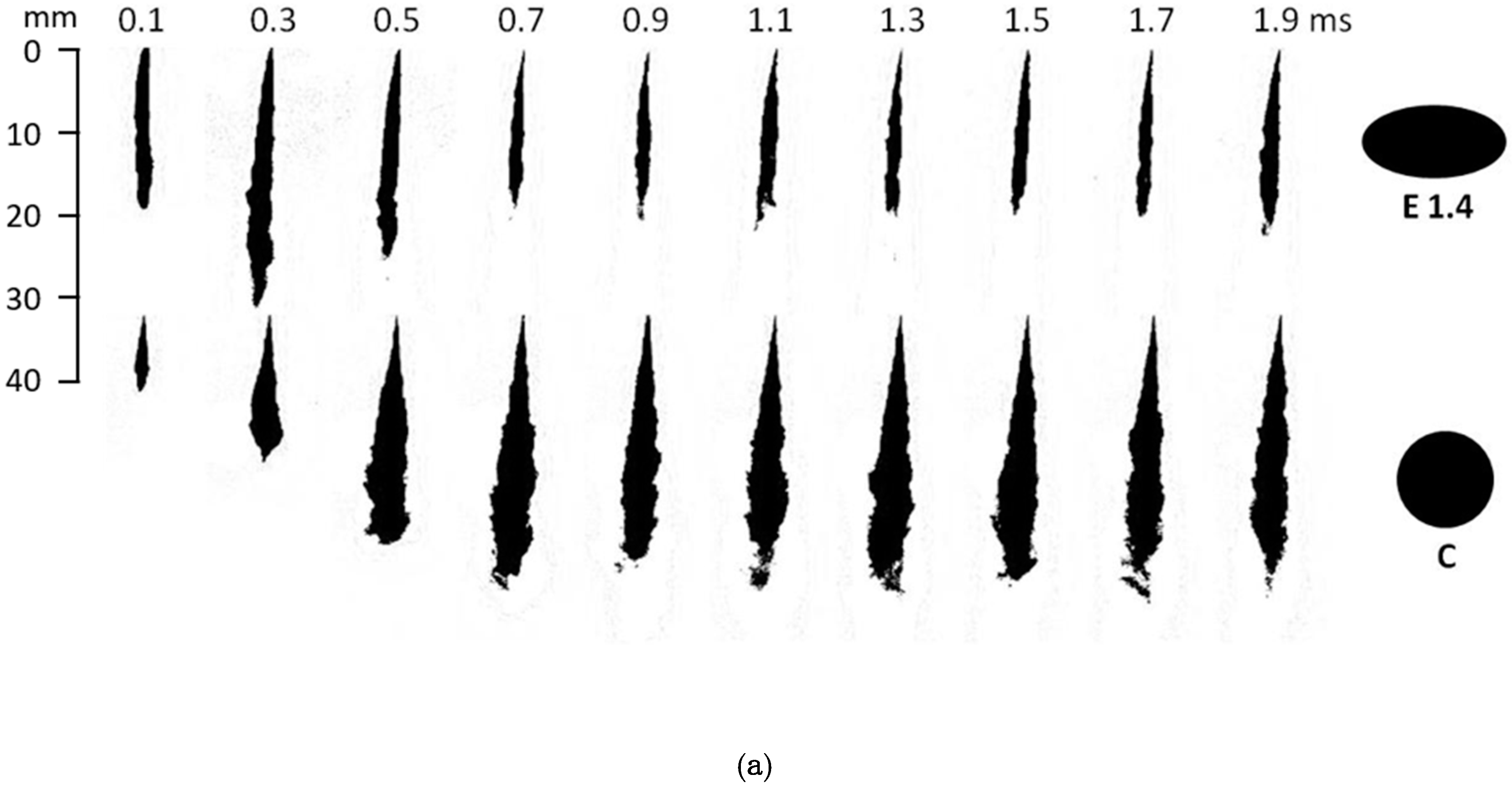
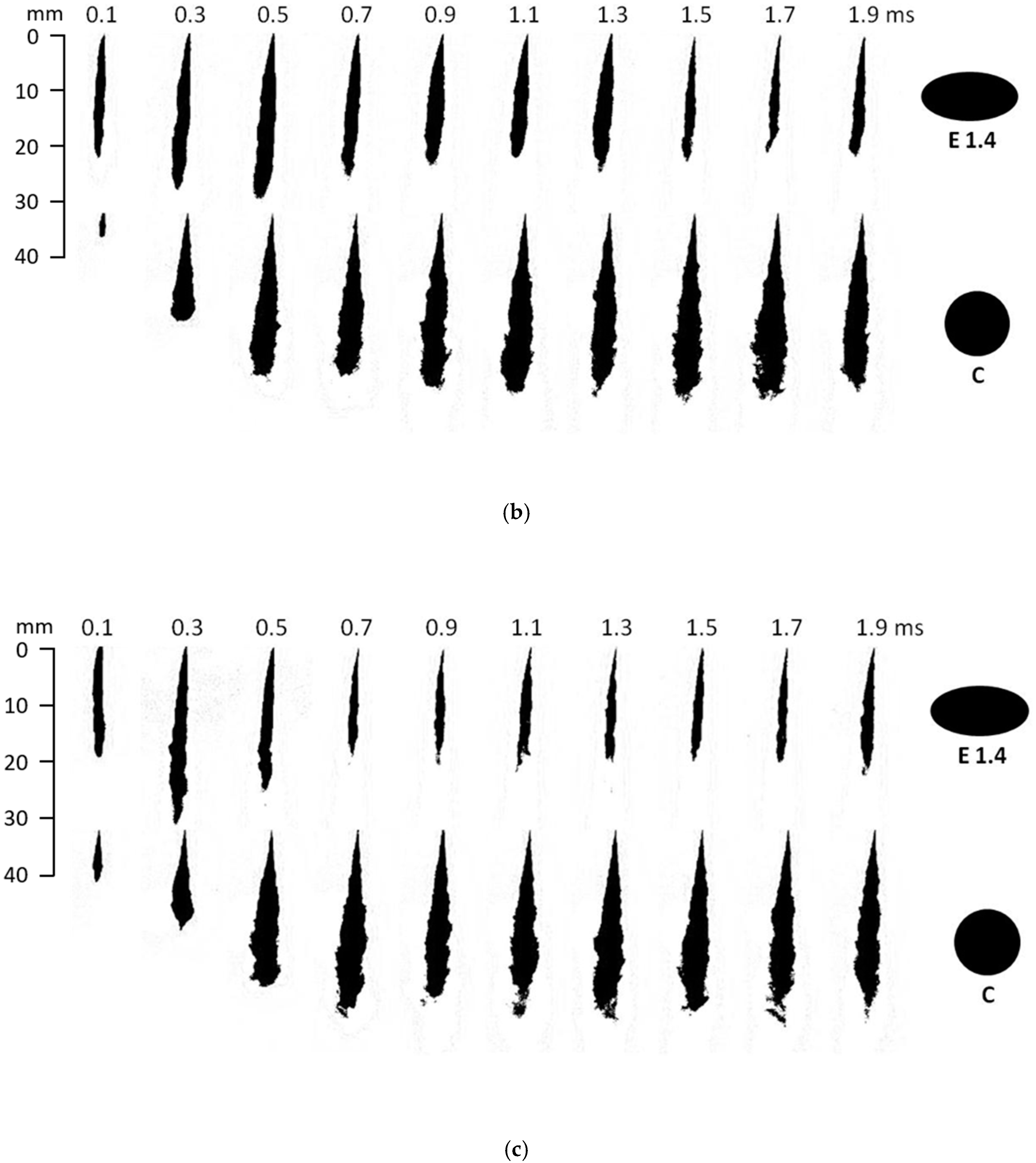
Figure 3 presents the development of the spray liquid-phase images at different injection pressures, with a fixed bulk temperature of 600 K. The present work investigates liquid-phase penetration, and therefore all of the images were captured at the major view planes of the elliptical nozzle. Considering the fluctuation in the process of the spray, ten spray images were taken under the respective conditions for each injection shot. Please note that the spray image presented in Figure 3 is only one injection event. From Figure 3, it can be seen that the spray liquid-phase of the elliptical nozzle is shorter than the circular spray in the steady state. Additionally, as compared to the circular nozzle spray, the distribution area of the elliptical spray liquid-phase is smaller. In general, lower liquid-phase penetration and smaller distributions are evidence of faster and better fuel and air mixture qualities [27]. Moreover, in the following sections, the influence of the elliptical diesel nozzle, the ambient and injection conditions on the liquid-phase penetration will be analyzed in more detail.

4. Results and Discussion

4.1. The Effects of Injection Pressure on the Spray Liquid-Phase Penetration

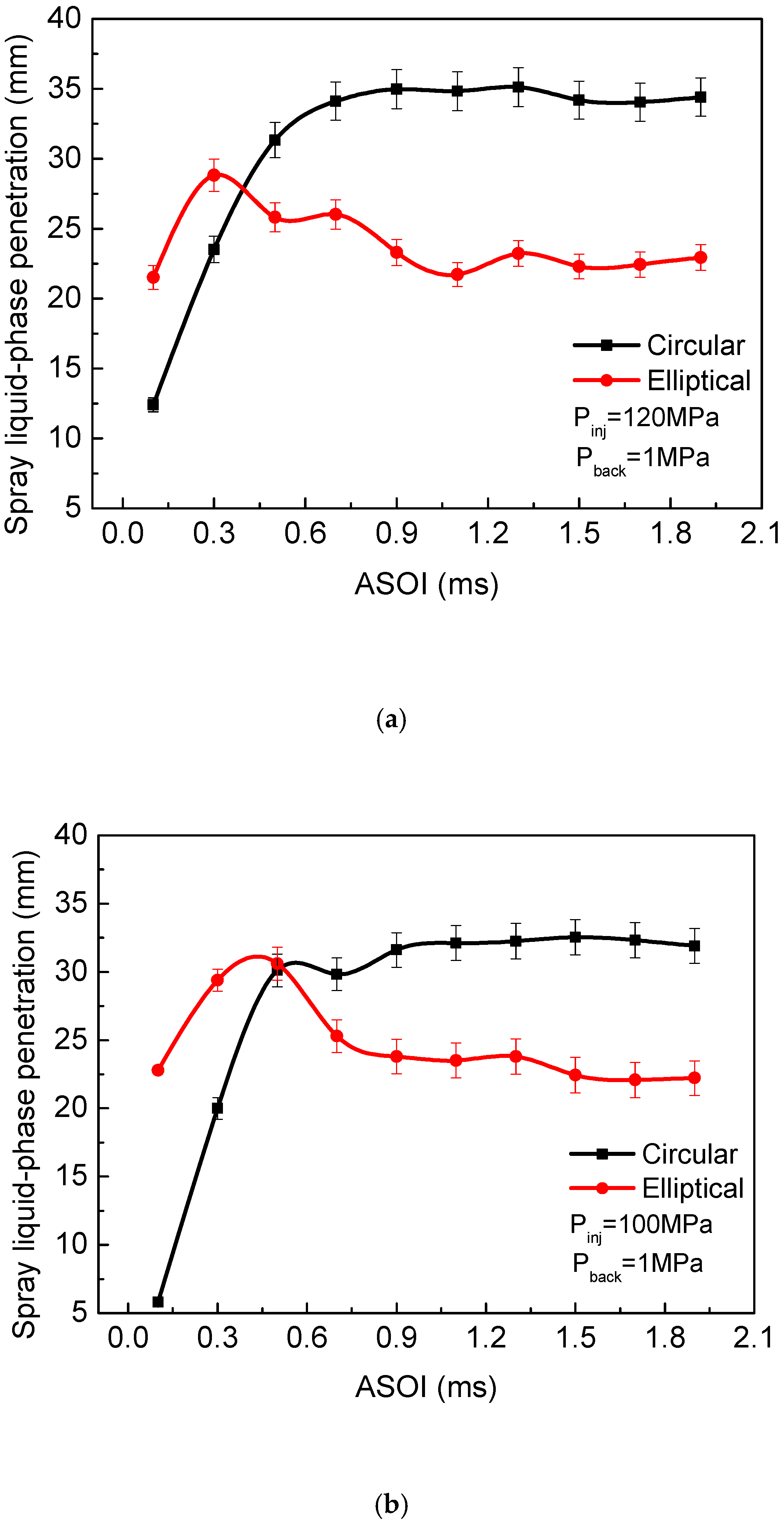
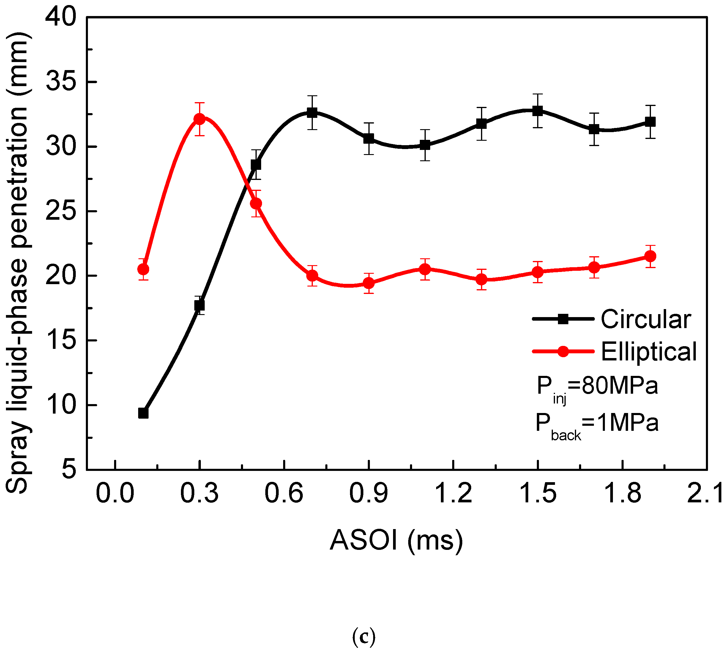
In Figure 4, the spray liquid-phase penetration is depicted against injection time for orifices with different cross-section shapes under various injection pressure conditions, and a fixed ambient temperature of 600 K. The time used in the present research work is the time since the start of the injection (ASOI). Based on Figure 4, it can be seen that the elliptical liquid-phase penetration increases during the early stages of injection, and then tends to remain steady at the end of the injection. The variation is the same as for the circular spray in previous research works [30,31]. Additionally, very early injection times, the elliptical spray liquid-phase penetration was longer than the circular one. However, for quasi-stationary injection, the important finding is that the elliptical spray liquid-phase penetration is shorter than the circular one, indicating that the application of the elliptical hole nozzle is helpful for speeding up liquid core fragmentation due to the instability deformation of the asymmetric elliptical jet and the axis-switching phenomenon, as well as the axis-switching behaviors that were found in our previous work [10].
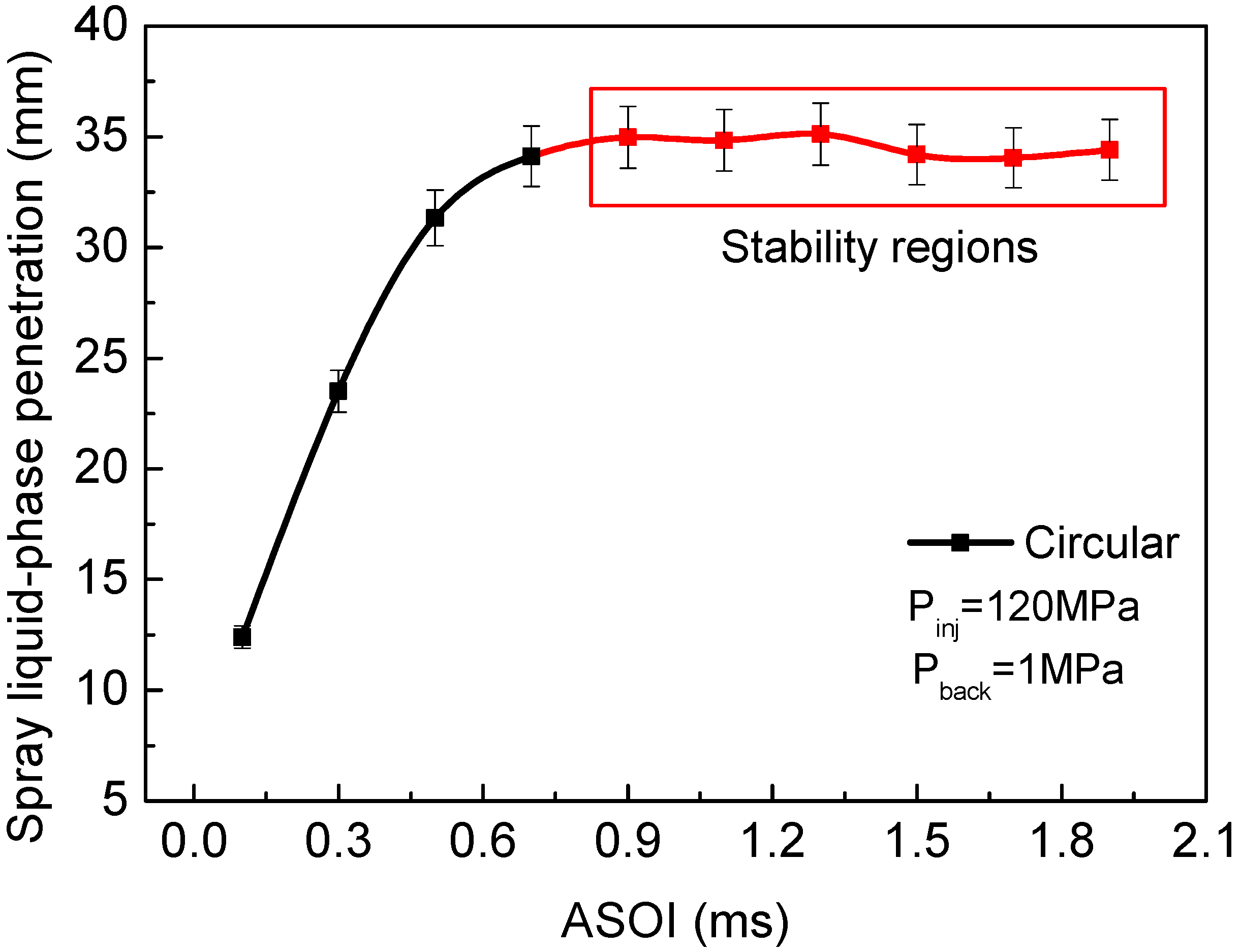
In order to analyze the influence of the injection parameters on the length of the stable spray liquid phase, Figure 5 shows the method used to obtain the stabilized value of the spray liquid-phase penetration. The red line window, which was used to calculate the average of the spray liquid-phase penetration, was selected in order to capture the stabilized region for circular and elliptical sprays under various injection conditions. The average of the last six values in the later stage of injection was taken as the steady spray liquid-phase penetration.
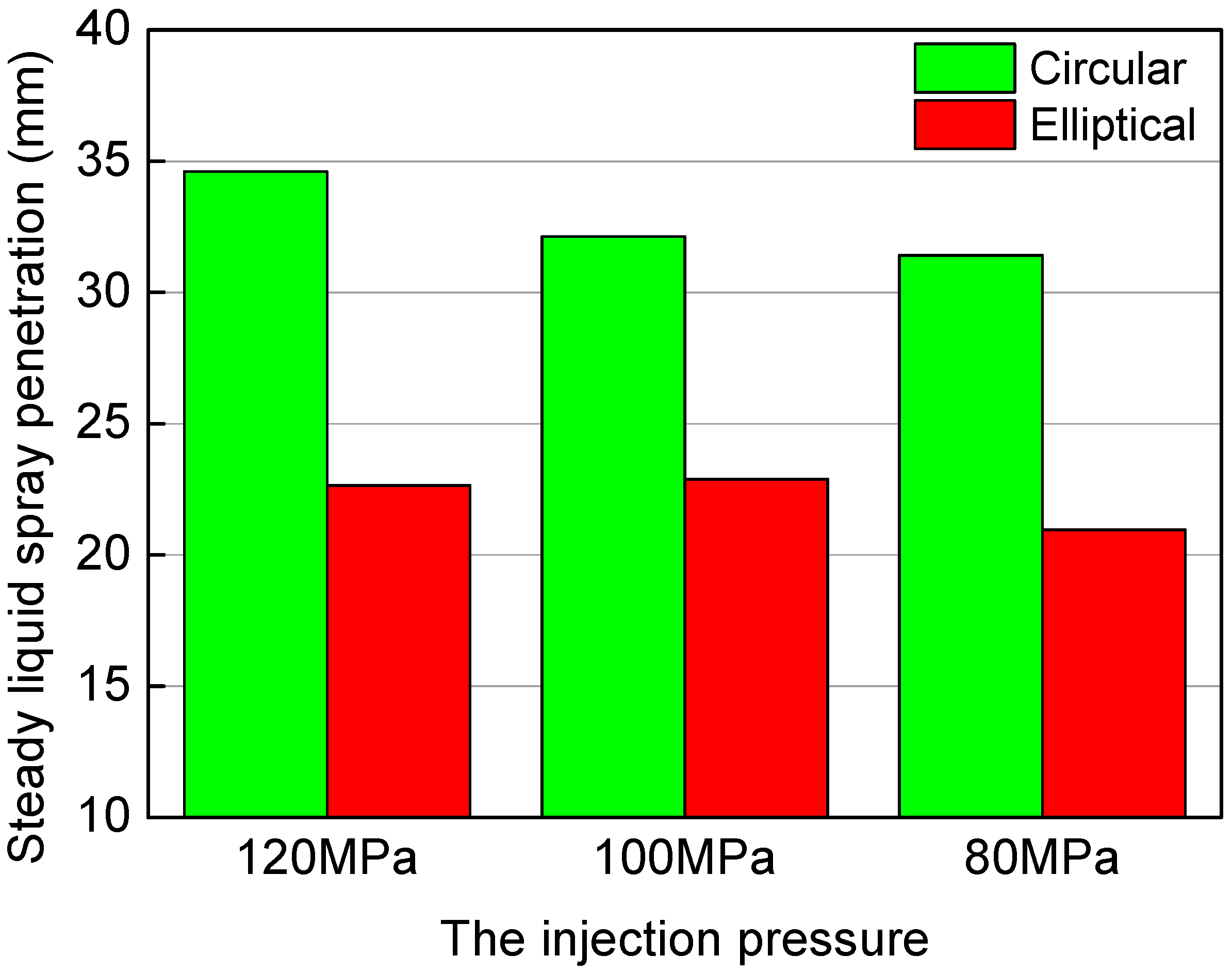
Figure 6 demonstrates the steady spray liquid-phase penetration for the circular and the elliptical sprays. As can be seen from Figure 6, the elliptical orifice presents a shorter steady spray liquid-phase penetration than the circular spray under all injection conditions. In particular, the steady spray liquid-phase penetration was reduced by 34.5% with the application of the elliptical hole nozzle as compared to the circular one at the injection pressure of 120 MPa; the results show that the elliptical hole nozzle effectively accelerates the unstable fracture of the liquid jet, thus decreasing the length of the spray liquid-phase. Additionally, for the same geometrical orifice, the difference in spray liquid-phase penetration decreases as the injection pressure increases, and these presented results indicate that the injection pressure has little effect on the spray liquid-phase penetration of the two geometric orifices, as has also been reported previously for circular diesel nozzles [32,33].

4.2. The Effects of Bulk Temperature on Spray Liquid-Phase Penetration

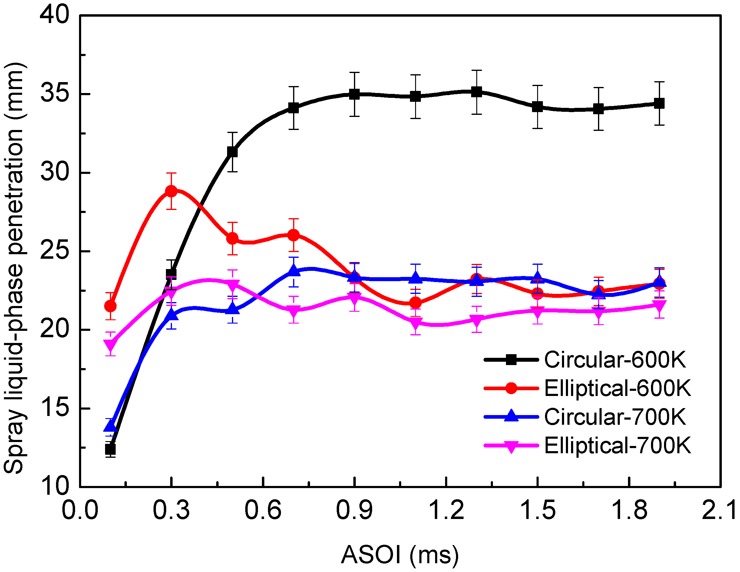
Bulk temperature is one of the most important parameters for analyzing evaporative diesel sprays, significantly influencing the spray and combustion characteristics. The effects of different ambient temperatures on circular and elliptical spray liquid-phase penetration are presented in Figure 7. For the circular liquid-phase penetration, as expected, the curves for each temperature overlap at the beginning of the injection, while for the elliptical spray, there was no overlap. From Figure 7, it can be found that increasing the ambient temperature decreases spray liquid-phase penetration for both nozzles; Xu et al. [34] and Payri et al. [35] have reported similar results previously. Additionally, for the same ambient temperature, it is noted that using an elliptical orifice leads to shorter liquid-phase penetration, as well as a shorter period of time to achieve a quasi-steady liquid length. The application of an elliptical orifice can effectively shorten the length of the liquid-phase penetration and thus avoid the fuel impingement under the realistic diesel engine operating conditions. Additionally, the shorter liquid-phase penetration for the elliptical orifice indicated better fuel and air mixture quality, which is helpful for reducing engine exhaust soot emissions.
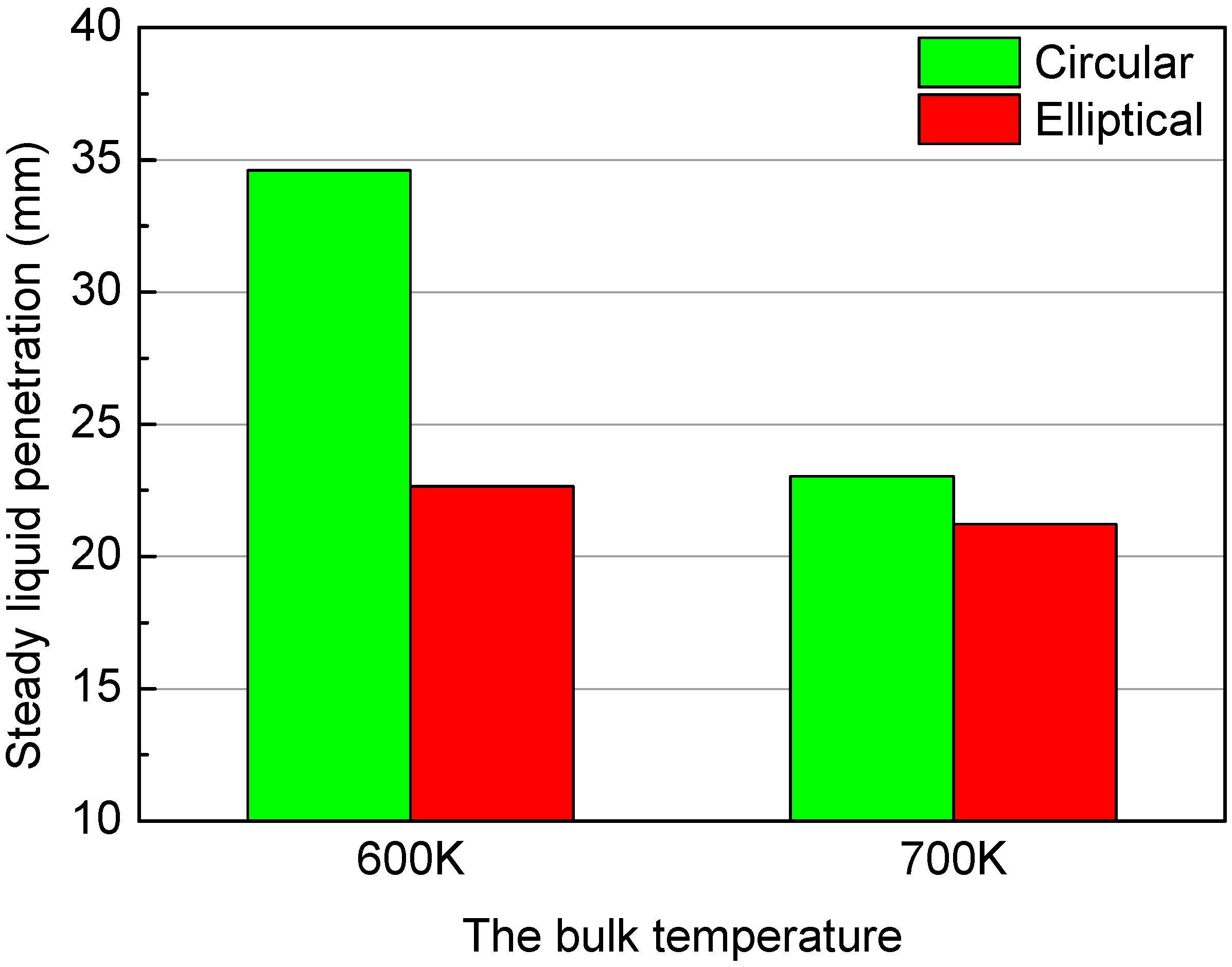
Figure 8 depicts the steady liquid-phase penetration at various ambient temperatures, indicating that increasing the ambient temperature reduces the liquid-phase penetration for both nozzles, and the differences in steady liquid-phase penetration between circular and elliptical orifice decrease with an increase in ambient temperature. For the ambient temperature of 700 K, in particular, the steady elliptical spray liquid-phase penetration was 7.9% smaller than that of the circular spray. Otherwise, for an ambient temperature of 700 K, the difference in steady liquid-phase penetration between circular and elliptical orifice was 84.8% smaller than the difference for the ambient temperature of 600 K. The reason for this is probably that the influence of temperature on the spray is greater than the impact of the nozzle cross-section shape on the liquid-phase penetration, indicating that the high temperature reduces the difference between the steady liquid-phase penetration of circular and elliptical sprays.

4.3. The Effects of Backpressure on Spray Liquid-Phase Penetration

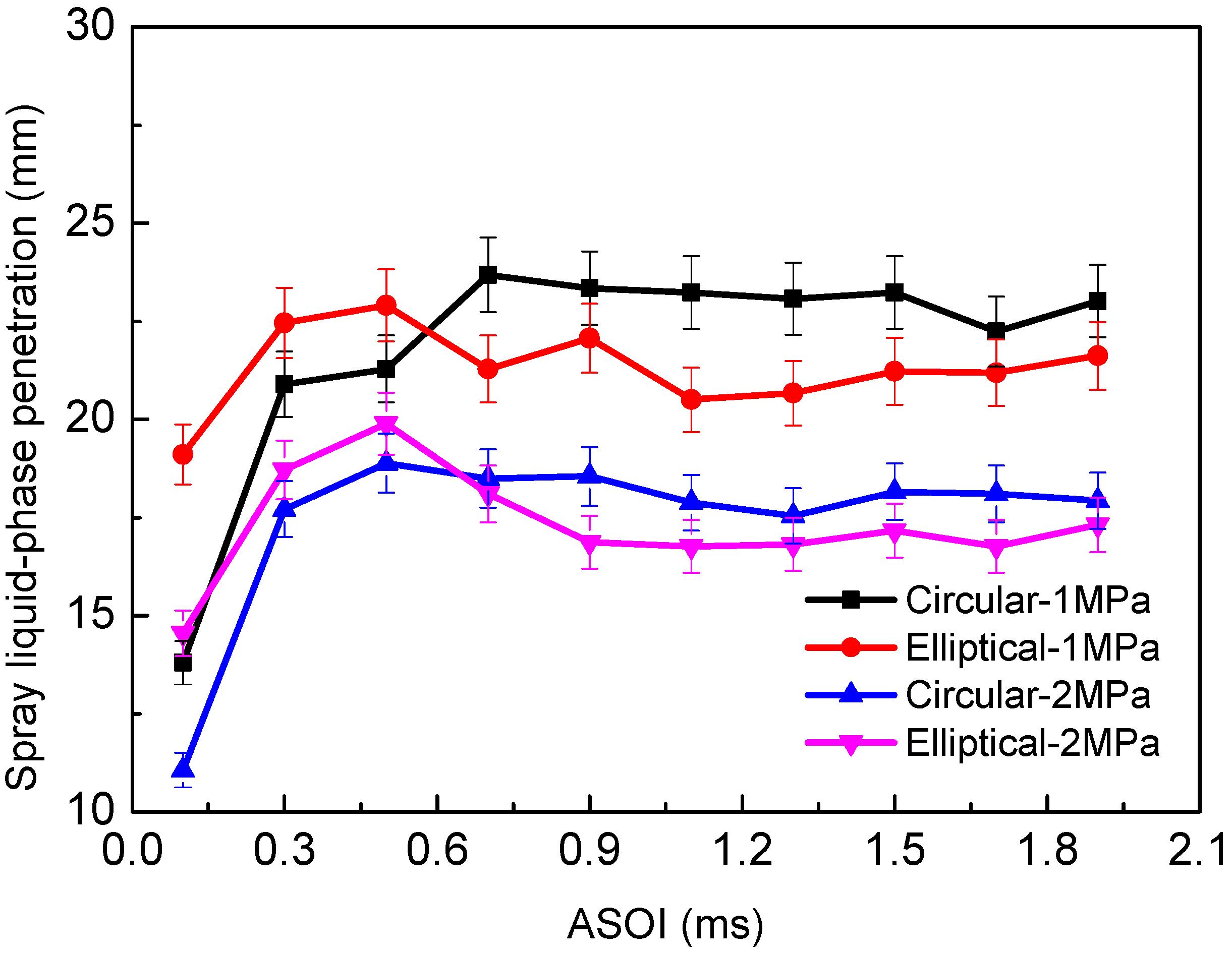
Figure 9 presents the spray liquid-phase penetration against the injection time with different cross-section shapes at various backpressures; the injection pressure is fixed at 120 MPa and the ambient temperature is 700 K. From Figure 9, the results show that increasing the backpressure decreases the liquid-phase penetration for both nozzles; note that Shang et al. [36] and Li et al. [37] observed the same trend in their experimental results. Because the high ambient pressure can reduce the initial spray velocity, on the other hand, the high backpressure is beneficial for increasing the spray cone angle, thus entraining more hot gas in the spray center. Both factors will result in a reduction in liquid-phase penetration when the backpressure is increased. Interestingly, the difference of the liquid-phase penetration between the circular and elliptical nozzle decreases with higher backpressure.
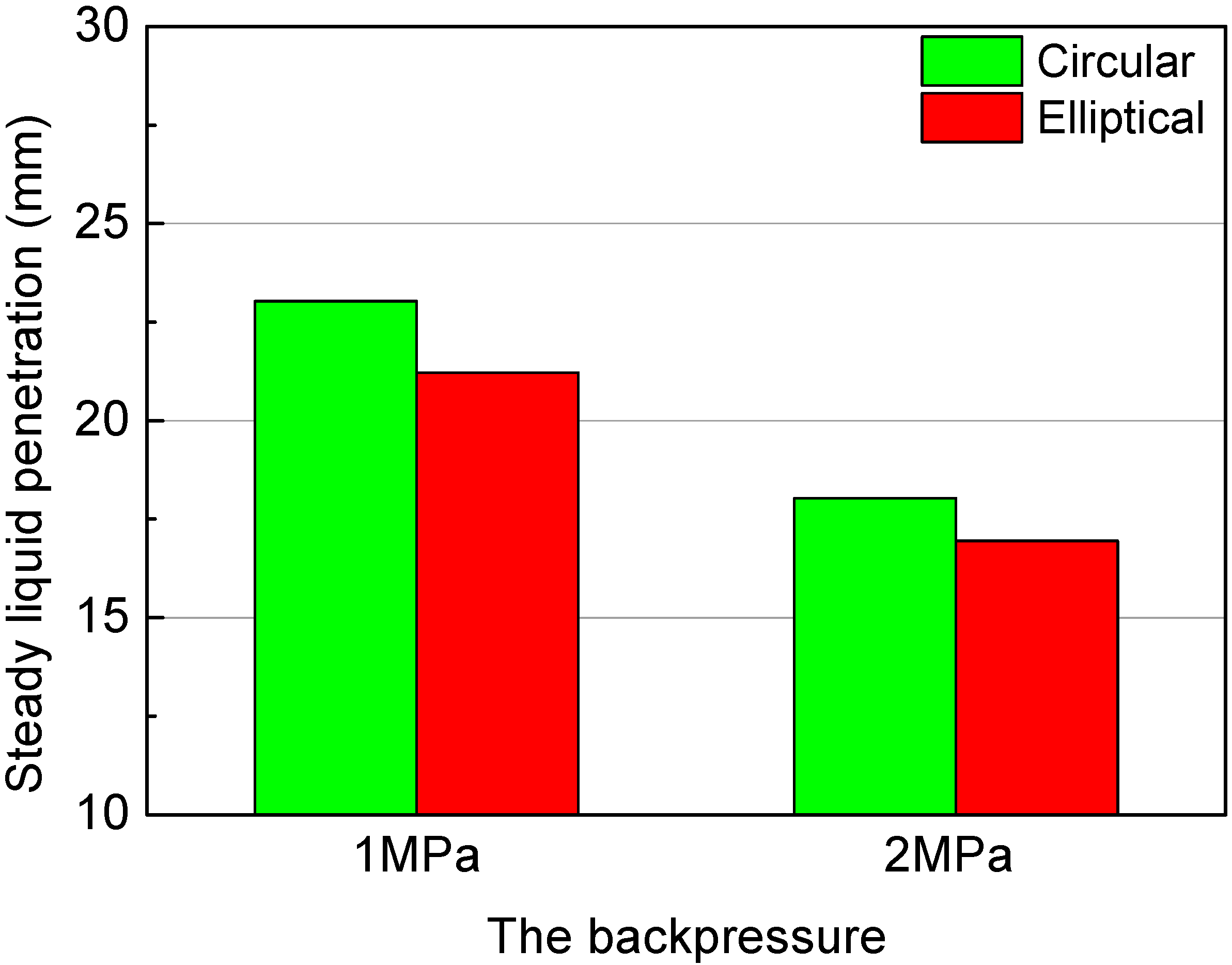
In Figure 10, the steady liquid-phase penetration results at different backpressures are plotted. From Figure 10, the steady liquid-phase penetration reduced as the backpressure increases, but the differences of the steady liquid-phase penetration for the circular and elliptical orifice are reduced under the condition of higher ambient density. For the backpressure of 2 MPa, in particular, the steady liquid penetration of the elliptical spray is only 6% smaller than the circular spray, probably because under the environment of high backpressure suppresses in axis-switching and deformation behaviors of the elliptic spray.

5. Conclusions

The spray liquid breakup behaviors for diesel nozzles with the application of non-circular cross-section shapes (elliptical, circular) were studied using the Mie-scattering method under evaporative conditions. This study provides a comprehensive analysis of the influence of variables such as elliptical and circular orifices, injection pressures (80 MPa, 100 MPa, 120 MPa), bulk temperatures (600 K, 700 K), and backpressures (1 MPa, 2 MPa) on spray liquid-phase penetration characteristics. The following conclusions can be drawn:
(1) The elliptical spray liquid length increased in the early stages of injection, and tended to be steady then. The elliptical spray liquid-phase penetration was smaller than the circular spray at the end of the injection, due to the deformation and the axis-switching behaviors both being helpful for accelerating the breakup of the elliptical liquid core.
(2) The steady spray liquid-phase penetration of the elliptical diesel nozzle was 34.5% lower than the circular one, indicating that the use of an elliptical orifice nozzle can effectively shorten the liquid-phase length. For the same geometrical orifice, the differences in the spray liquid-phase penetration were reduced with an increase in injection pressure, suggesting that injection pressure has little impact on the spray liquid-phase penetration for either geometrical orifice.
(3) Increasing the ambient temperature is able to reduce the spray liquid-phase penetration for both orifices. The differences in steady liquid-phase penetration between circular and elliptical nozzles were reduced with an increase in ambient temperature. Under high-bulk temperature conditions of 700 K, the steady elliptical spray liquid-phase penetration was 7.9% lower than the circular spray.
(4) Increasing the backpressure is able to lower the liquid-phase penetration for both orifices, because higher ambient gas density consumes the momentum of the spray. With the increase of the backpressure, the differences in the steady liquid-phase penetration between circular and elliptical orifices were reduced, probably due to the axis-switching and deformation behaviors of the elliptical jet being restrained under high-backpressure conditions.
(5) With the application of the elliptical orifice, which can effectively decrease the liquid-phase penetration, it can be inferred that for small cylinder size diesel engines, the use of elliptical holes can effectively avoid fuel impingement. Additionally, the lower liquid-phase penetration for the elliptical orifice indicated better and faster fuel and air mixture quality, which is helpful for reducing engine emissions.

Author Contributions

B.X. and B.Y. designed research; B.X. and S.Y. performed research, analyzed data, and wrote the paper; H.J. supervised research and reviewed the paper. All authors have read and agreed to the published version of the manuscript.

Funding

Graduate Student Innovation Fund Project of Jiangsu Province [KYCX17_1778]; Science and Technology on Scramjet Laboratory Project of China [STS/MY-KFKT-2017001]; Jiangsu Province Post-Doctoral Fund [2018K031B].

Acknowledgments

This work was supported by the contribution of Graduate Student Innovation Fund Project of Jiangsu Province [KYCX17_1778]; Science and Technology on Scramjet Laboratory Project of China [STS/MY-KFKT-2017001]; Jiangsu Province Post-Doctoral Fund [2018K031B]; The Priority Academic Program Development of Jiangsu Higher Education Institutions [PAPD].

Conflicts of Interest

The authors declare no conflict of interest.

References

  1. Wang, Z.; Shi, S.; Huang, S.; Tang, J.; Du, T.; Cheng, X.; Huang, R.; Chen, J.-Y. Effects of water content on evaporation and combustion characteristics of water emulsified diesel spray. Appl. Energy 2018, 226, 397–407. [Google Scholar] [CrossRef]
  2. Tian, J.; Zhao, M.; Long, W.; Nishida, K.; Fujikawa, T.; Zhang, W. Experimental study on spray characteristics under ultra-high injection pressure for DISI engines. Fuel 2016, 186, 365–374. [Google Scholar] [CrossRef]
  3. Nishida, K.; Zhu, J.; Leng, X.; He, Z. Effects of micro-hole nozzle and ultra-high injection pressure on air entrainment, liquid penetration, flame lift-off and soot formation of diesel spray flame. Int. J. Engine Res. 2017, 18, 51–65. [Google Scholar] [CrossRef]
  4. Kiplimo, R.; Tomita, E.; Kawahara, N.; Yokobe, S. Effects of spray impingement, injection parameters, and EGR on the combustion and emission characteristics of a PCCI diesel engine. Appl. Therm. Eng. 2012, 37, 165–175. [Google Scholar] [CrossRef]
  5. Ge, M.; Liang, X.; Yu, H.; Wang, Y.; Zhang, H. Effect of Lube Oil Film Thickness on Spray/Wall Impingement with Diesel, M20 and E20 Fuels; SAE Technical Paper Series; SAE International: Warrendale, PA, USA, 2017; 01-0847. [Google Scholar]
  6. Yu, S.; Yin, B.; Deng, W.; Jia, H.; Ye, Z.; Xu, B.; Xu, H. Experimental study on the diesel and biodiesel spray characteristics emerging from equilateral triangular orifice under real diesel engine operation conditions. Fuel 2018, 224, 357–365. [Google Scholar] [CrossRef]
  7. Yunyi, G.; Changwen, L.; Yezhou, H.; Zhijun, P. An Experimental Study on Droplet Size Characteristics and Air Entrainment of Elliptic Sprays; SAE Technical Paper Series; SAE International: Warrendale, PA, USA, 1998. [Google Scholar]
  8. Yu, S.; Yin, B.; Deng, W.; Jia, H.; Ye, Z.; Xu, B.; Xu, H. Experimental study on the spray characteristics discharging from elliptical diesel nozzle at typical diesel engine conditions. Fuel 2018, 221, 28–34. [Google Scholar] [CrossRef]
  9. Yu, S.; Yin, B.; Deng, W.; Jia, H.; Ye, Z.; Xu, B.; Xu, H. Internal flow and spray characteristics for elliptical orifice with large aspect ratio under typical diesel engine operation conditions. Fuel 2018, 228, 62–73. [Google Scholar] [CrossRef]
  10. Yu, S.; Yin, B.; Deng, W.; Jia, H.; Ye, Z.; Xu, B.; Xu, H. An experimental comparison of the elliptical and circular nozzles spray and mixing characteristics under different injection pressures. Fuel 2019, 236, 1474–1482. [Google Scholar] [CrossRef]
  11. Ku, K.-W.; Lee, Y.-J.; Kim, I.-S.; Lee, C.-W. Experimental study of the effects of nozzle hole geometry for di diesel engine. J. ILASS-Korea 2007, 12, 154–159. [Google Scholar]
  12. Matsson, A.; Jacobsson, L.; Andersson, S. The Effect of Elliptical Nozzle Holes on Combustion and Emission Formation in a Heavy Duty Diesel Engine; SAE Technical Paper Series; SAE International: Warrendale, PA, USA, 2000; 01-1251. [Google Scholar]
  13. Ho, C.-M.; Gutmark, E. Vortex induction and mass entrainment in a small-aspect-ratio elliptic jet. J. Fluid Mech. 1987, 179, 383–405. [Google Scholar] [CrossRef]
  14. Hong, J.G.; Ku, K.W.; Kim, S.R.; Lee, C.W. Effect of cavitation in circular nozzle and elliptical nozzles on the spray characteristic. At. Sprays 2010, 20, 877–886. [Google Scholar] [CrossRef]
  15. Hong, J.G.; Ku, K.W.; Lee, C.-W. Numerical simulation of the cavitating flow in an elliptical nozzle. At. Sprays 2011, 21, 237–248. [Google Scholar] [CrossRef]
  16. Sharma, P.; Fang, T. Spray and atomization of a common rail fuel injector with non-circular orifices. Fuel 2015, 153, 416–430. [Google Scholar] [CrossRef]
  17. Sharma, P.; Fang, T. Breakup of liquid jets from non-circular orifices. Exp. Fluids 2014, 55. [Google Scholar] [CrossRef]
  18. Cung, K.; Moiz, A.A.; Shah, B.; Kalaskar, V.; Miwa, J.; Abidin, Z. Evaluation of Diesel Spray with Non-Circular Nozzle—Part I: Inert Spray; SAE Technical Paper Series; SAE International: Warrendale, PA, USA, 2019; 01-0065. [Google Scholar]
  19. Srinivasan, R.; Bowersox, R.D.W. Transverse Injection through Diamond and Circular Ports into a Mach 5.0 Freestream. AIAA J. 2008, 46, 1944–1962. [Google Scholar] [CrossRef]
  20. Jadidi, M.; Sreekumar, V.; Dolatabadi, A. Breakup of elliptical liquid jets in gaseous crossflows at low Weber numbers. J. Vis. 2018, 22, 259–271. [Google Scholar] [CrossRef]
  21. Kasyap, T.V.; Sivakumar, D.; Raghunandan, B.N. Breakup of liquid jets emanating from elliptical orifices at low flow conditions. At. Sprays 2008, 18, 645–668. [Google Scholar] [CrossRef]
  22. Kasyap, T.; Sivakumar, D.; Raghunandan, B. Flow and breakup characteristics of elliptical liquid jets. Int. J. Multiph. Flow 2009, 35, 8–19. [Google Scholar] [CrossRef]
  23. Morad, M.R.; Khosrobeygi, H. Penetration of Elliptical Liquid Jets in Low-Speed Crossflow. J. Fluids Eng. 2018, 141, 011301. [Google Scholar] [CrossRef]
  24. Molina, S.; Salvador, F.; Carreres, M.; Jaramillo, D.; Rubio, F.J.S. A computational investigation on the influence of the use of elliptical orifices on the inner nozzle flow and cavitation development in diesel injector nozzles. Energy Convers. Manag. 2014, 79, 114–127. [Google Scholar] [CrossRef]
  25. Chiatti, G.; Chiavola, O.; Palmieri, F.; Pompei, R. On the Influence of the Slot Orifice in Diesel Common Rail Nozzle. Open Fuels Energy Sci. J. 2018, 11, 55–69. [Google Scholar] [CrossRef] [Green Version]
  26. Yu, S.; Yin, B.; Deng, W.; Jia, H.; Ye, Z.; Xu, B.; Xu, H. Experimental study on the spray and mixing characteristics for equilateral triangular and circular nozzles with diesel and biodiesel under high injection pressures. Fuel 2019, 239, 97–107. [Google Scholar] [CrossRef]
  27. Payri, R.; Salvador, F.; Gimeno, J.; Zapata, L.; Rubio, F.J.S. Diesel nozzle geometry influence on spray liquid-phase fuel penetration in evaporative conditions. Fuel 2008, 87, 1165–1176. [Google Scholar] [CrossRef]
  28. Pastor, J.V.; Arrègle, J.; Palomares, A. Diesel spray image segmentation with a likelihood ratio test. Appl. Opt. 2001, 40, 2876–2885. [Google Scholar] [CrossRef]
  29. Pastor, J.V.; Arrègle, J.; García, J.M.; Zapata, L.D. Segmentation of diesel spray images with log-likelihood ratio test algorithm for non-Gaussian distributions. Appl. Opt. 2007, 46, 888–899. [Google Scholar] [CrossRef]
  30. Zheng, L.; Ma, X.; Wang, Z.; Wang, J. An optical study on liquid-phase penetration, flame lift-off location and soot volume fraction distribution of gasoline–diesel blends in a constant volume vessel. Fuel 2015, 139, 365–373. [Google Scholar] [CrossRef]
  31. Payri, R.; Giraldo, J.S.; Ayyapureddi, S.; Versey, Z. Experimental and analytical study on vapor phase and liquid penetration for a high pressure diesel injector. Appl. Therm. Eng. 2018, 137, 721–728. [Google Scholar] [CrossRef]
  32. Martínez-Martínez, S.; Sánchez-Cruz, F.; Riesco-Ávila, J.; Gallegos, A.; Aceves, S. Liquid penetration length in direct diesel fuel injection. Appl. Therm. Eng. 2008, 28, 1756–1762. [Google Scholar] [CrossRef]
  33. Kook, S.; Pickett, L.M. Liquid length and vapor penetration of conventional, Fischer–Tropsch, coal-derived, and surrogate fuel sprays at high-temperature and high-pressure ambient conditions. Fuel 2012, 93, 539–548. [Google Scholar] [CrossRef]
  34. Xu, M.; Cui, Y.; Deng, K. One-dimensional model on liquid-phase fuel penetration in diesel sprays. J. Energy Inst. 2016, 89, 138–149. [Google Scholar] [CrossRef]
  35. Payri, R.; Gimeno, J.; Bardi, M.; Plazas, A.H. Study liquid length penetration results obtained with a direct acting piezo electric injector. Appl. Energy 2013, 106, 152–162. [Google Scholar] [CrossRef] [Green Version]
  36. Shang, W.; He, Z.; Wang, Q.; Cao, J.; Li, B.; Leng, X.; Tamilselvan, P.; Li, D. Experimental and analytical study on capture spray liquid penetration and combustion characteristics simultaneously with Hydrogenated Catalytic Biodiesel/Diesel blended fuel. Appl. Energy 2018, 226, 947–956. [Google Scholar] [CrossRef]
  37. Li, D.; He, Z.; Xuan, T.; Zhong, W.; Cao, J.; Wang, Q.; Wang, P. Simultaneous capture of liquid length of spray and flame lift-off length for second-generation biodiesel/diesel blended fuel in a constant volume combustion chamber. Fuel 2017, 189, 260–269. [Google Scholar] [CrossRef]
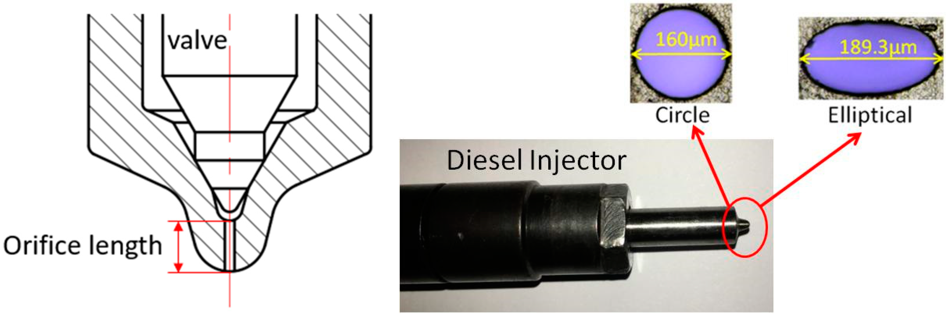
Figure 1. The diesel injector with circular and elliptical holes.
Energies 13 02234 g001
Figure 2. Experimental equipment diagram. (a) Mie-scattering test schematic; (b) Constant volume chamber.
Energies 13 02234 g002
Figure 3. Evolution of liquid mass fraction for various geometrical orifices (Pback = 1 MPa, Tbulk = 600 MPa). (a) The injection pressure of 120 MPa; (b) The injection pressure of 100 MPa; (c) The injection pressure of 80 MPa. The original spray images were obtained using the Mie-scattering method, and these need to be subtracted from the background image, which were taken before the injection began. After that, the spray liquid-phase images were distinguished from the background with an in-house MATLAB code. The spray liquid-phase penetration was identified from the background with an intensity threshold calculated as suggested in [28,29]. After this, the spray liquid-phase was analyzed for each spray image. The spray liquid-phase length is the length between the tip of the spray and the orifice tip. The final liquid-phase length is the average of ten spray images, and the error analysis for the spray liquid-phase penetration indicated that the difference from the average value was less than 4.0%.
Energies 13 02234 g003aEnergies 13 02234 g003b
Figure 4. The spray liquid-phase penetration for various injection pressures and the bulk temperature is fixed at 600 K. (a)The injection pressure of 120 MPa; (b) The injection pressure of 100 MPa; (c) The injection pressure of 80 MPa.
Energies 13 02234 g004aEnergies 13 02234 g004b
Figure 5. Spray liquid-phase penetration averaging methodology. The colored area represents the domain where the average has been calculated.
Energies 13 02234 g005
Figure 6. Steady spray liquid-phase penetration for circular and elliptical nozzles at a bulk temperature of 600 K.
Energies 13 02234 g006
Figure 7. Spray liquid-phase penetration for different bulk temperatures (Pinj = 120 MPa, Pbcak = 1 MPa).
Energies 13 02234 g007
Figure 8. Steady spray liquid-phase penetration for circular and elliptical nozzles at different bulk temperatures (Pinj = 120 MPa, Pbcak = 1 MPa).
Energies 13 02234 g008
Figure 9. Spray liquid-phase penetration for different backpressures (Pinj = 120 MPa, Tbulk = 700 K).
Energies 13 02234 g009
Figure 10. Steady spray liquid-phase penetration for circular and elliptical nozzles at different backpressures (Pinj = 120 MPa, Tbulk = 700 K).
Energies 13 02234 g010
Table 1. The parameters of different orifices.
Nozzle Major Axis [μm]Minor Axis [μm]Cross-Section Area [μm2]Perimeter [μm]Orifice Length [mm]Hydraulic Diameter [mm]
Circle16016020,106.2205.71.23160
Elliptical189.3135.220,106.2533.01.23150.9
Table 2. Spray visualization text conditions.
ParameterValue-Type
FuelBiodiesel
Injection pressure (Pinj)80 MPa, 100 MPa, 120 MPa
Backpressure (Pback)1 MPa, 2 MPa
Gas propertyNitrogen
Ambient temperature (Tbulk)600 K, 700 K
Table 3. Biodiesel fuel used and its properties.
Physical PropertiesBiodiesel
Density (kg/m3)876
Kinetic viscosity (mm2/s)(40 °C)4.52
Surface tension (mN/m)35.2
Flashpoint temperature (°C)169.0