Article

Core Stress Analysis of Amorphous Alloy Transformer for Rail Transit under Different Working Conditions

Department of Electrical Engineering, Faculty of Engineering, The Hong Kong Polytechnic University, Hong Kong 999077, China
*
Author to whom correspondence should be addressed.
Energies 2021, 14(1), 164; https://doi.org/10.3390/en14010164
Submission received: 15 October 2020 / Revised: 16 December 2020 / Accepted: 17 December 2020 / Published: 30 December 2020
(This article belongs to the Special Issue Advanced Electric Vehicle Techniques)

Abstract

:
The rail transit system is a large electric vehicle system that is strongly dependent on the energy technologies of the power system. The use of new energy-saving amorphous alloy transformers can not only reduce the loss of rail transit power, but also help alleviate the power shortage situation and electromagnetic emissions. The application of the transformer in the field of rail transit is limited by the problem that amorphous alloy is prone to debris. this paper studied the stress conditions of amorphous alloy transformer cores under different working conditions and determined that the location where the core is prone to fragmentation, which is the key problem of smoothly integrating amorphous alloy distribution transformers on rail transit power supply systems. In this study, we investigate the changes in the electromagnetic field and stress of the amorphous alloy transformer core under different operating conditions. The finite element model of an amorphous alloy transformer is established and verified. The simulation results of the magnetic field and stress of the core under different working conditions are given. The no-load current and no-load loss are simulated and compared with the actual experimental data to verify practicability of amorphous alloy transformers. The biggest influence on the iron core is the overload state and the maximum value is higher than the core stress during short circuit. The core strain caused by the side-phase short circuit is larger than the middle-phase short circuit.

1. Introduction

New materials are now increasingly used in the traditional power industry, bringing new solutions to the problems in the power system. The rail transit system is a large power system and the use of new energy-saving amorphous alloy transformers, not only can reduce the loss of rail transit power, but also help alleviate the power shortage situation [1,2,3]. Amorphous alloy is increasingly used in the iron core of power transformers due to its excellent low loss performance [4,5]. The advantages of using amorphous ferromagnetic alloys as a replacement for grain-oriented Si-steel in power transformers are widely reported owing to their low no-load core losses [6]. With the rapid development of amorphous alloy technology, the energy-saving advantages of amorphous alloy core distribution transformers have gradually been accepted by manufacturers and users [7,8]. Due to the shortcomings of amorphous alloy strips such as high hardness, poor short-circuit resistance, and high magnetostriction, the application and market promotion of amorphous alloy transformers are limited [9].
Therefore, it is important to study the stress conditions of amorphous alloy transformer cores under different working conditions, and determine where the core is prone to fragmentation. This is the key problem of smoothly integrating the amorphous alloy distribution transformer into rail transit power supply systems [3]. Many scholars have conducted research on improving the short-circuit resistance of amorphous alloys, reducing vibration and noise, and improving process measures [10]. Du et al. [11] focused on magnetostriction variation at different positions on the core surface to identify the correlations between the vibration amplitude and frequency. Liu et al. [12] presented a noise reduction measurement for amorphous alloy core distribution transformers and verification was carried out by some experiments. This paper emphasizes discussion on the effects of temperature and different materials. Liu et al. [13] developed an analytical model for copper loss calculation of Litz-wire in amorphous/nanocrystalline core-based high-frequency transformer. Haifeng et al. [14] designed a new type of clamp to withstand the huge force caused by short-circuit troubles and with the help of ANSYS software, the stress and strain of the end covers and the winding clamps were calculated, respectively, confirming the feasibility of this new structural method. Guo [15] proposes a three-dimensional buckling finite element method (FEM) to calculate the tilt limit force of the rectangular winding of an amorphous alloy transformer and experimental results of the short-circuit test on several amorphous alloy transformers verify the effectiveness of the proposed method.
With a large number of amorphous alloy transformers in operation, oil-immersed amorphous alloy transformer faults caused by iron core debris of amorphous alloy are more and more common [7]. There are two sources of core debris of amorphous alloys. One is the debris generated during the manufacturing, transportation, and assembly processes before operation, and the other is the core debris generated during operation of the amorphous alloy transformer. When the transformer is in operation, due to the mechanical sensitivity of the amorphous alloy, the transformer core will be deformed because of the electromagnetic force and the hysteresis force, resulting in core debris [16]. According to [16], in an amorphous alloy transformer, the strain caused by magnetostriction is much greater than the strain caused by the magnetic field force. Different working conditions such as unbalanced load, overload, and short circuit of transformer operation will cause changes of core force. After the amorphous alloy transformer is put into operation, the core debris will affect the electromagnetic performance, resulting in excessive temperature rise of the transformer, faster deterioration of the insulation medium, insulation failure, shorter effective working time of the transformer and increase of leakage field and electromagnetic interference.
Therefore, this paper focuses on the research gap in the amorphous alloy core developments and studies the stress of amorphous alloy transformer cores caused by magnetostriction under different working conditions and seeks to determine where the core is prone to fragmentation.
In this paper, the finite element analysis method is used to study stress conditions of amorphous alloy transformer cores under different working conditions. The finite element method [17] is an effective method to analyze the electromagnetic characteristics of amorphous alloy transformers. Bahmani [18] used the equivalent elliptic loop (EEL) method in Ansoft Maxwell 3D (Ansoft Corp., Pittsburgh, USA) to calculate the core losses of high-frequency high-power transformers and compared them with the empirical equations, verifying the practicability of the finite element method in electromagnetic field analysis. Chang et al. [19] studied the magneto mechanical effects of three-phase three-leg transformers with amorphous cores in different bending structures, where the magnetic properties of audible noises related to core vibrations are discussed. Experimental results in this paper indicate that amorphous-cored transformers with rectangular cores have higher vibration intensities.
This paper is organized as follows. Section 2 discusses the mathematical model of stress and strain induced by magnetostriction. Section 3 establishes a simulation model based on the structure, and physical and electromagnetic parameters of the actual amorphous alloy transformer. The simulation results of the magnetic field and stress of the core of amorphous alloy transformers under different working conditions are given in Section 4. The no-load current and no-load loss are simulated and compared with the actual experimental data to verify the practicability of amorphous alloy transformers in Section 5. The discussion and conclusion are given in Section 6 and Section 7, respectively. The research framework of the whole paper is shown in Figure 1.

2. Mathematical Model of Stress and Strain Induced by Magnetostriction

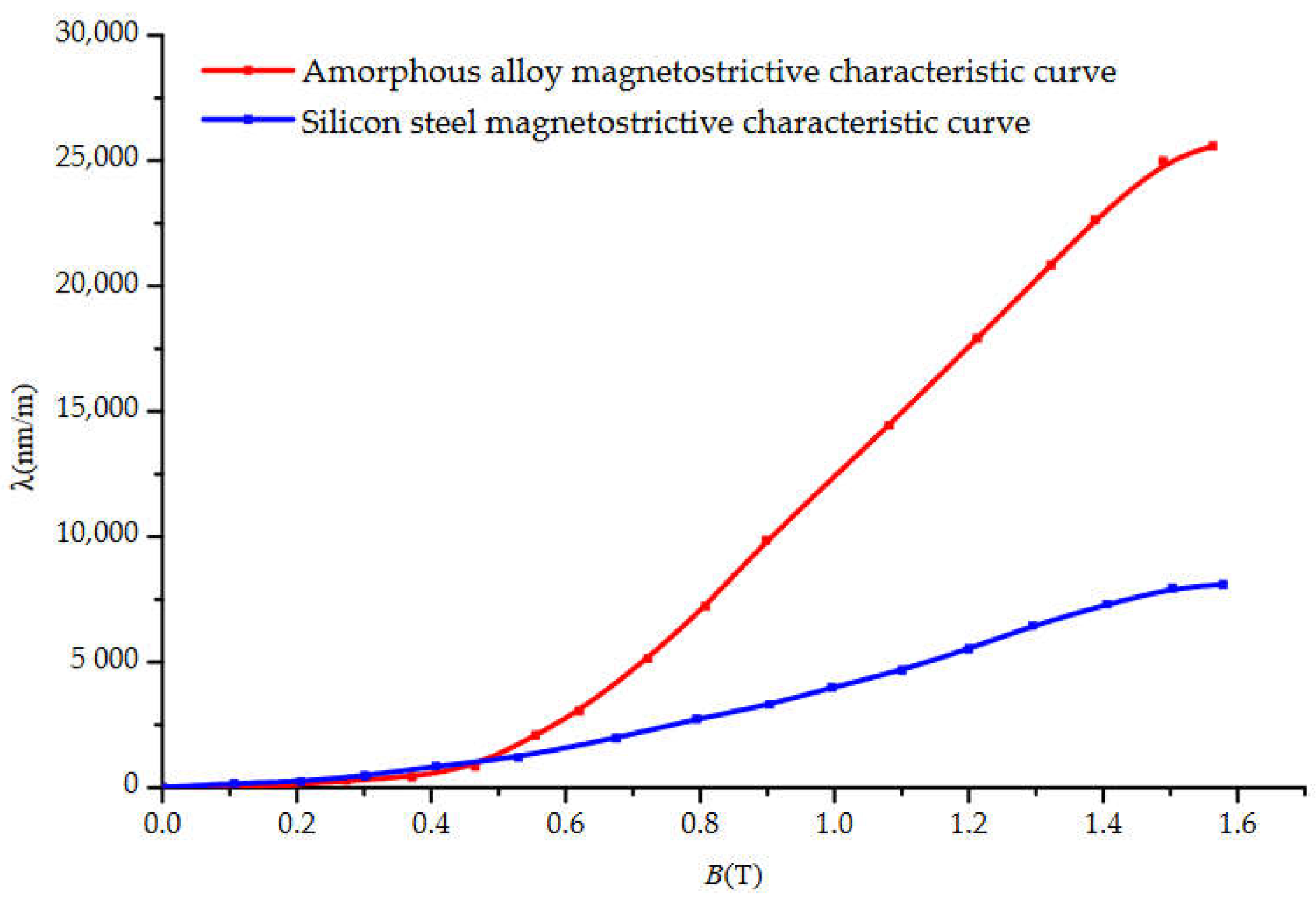
Amorphous alloy iron core is formed by stacking amorphous alloy strips, and there is eddy current and magnetic flux in the iron core column and iron yoke. Under the action of ampere force, the amorphous alloy core has slight deformation. The comparison of the magnetostriction coefficient of amorphous alloy and the magnetostriction coefficient of oriented silicon steel sheet is shown in Figure 2 [20]. It can be seen from the figure that under the same magnetic field strength, the degree of magnetostriction of the amorphous alloy is much higher than that of the silicon steel sheet. Correspondingly, under the action of the same magnetic field strength, the amorphous alloy core has a much larger heart shape variable than the silicon steel core. The largest strain caused by magnetostriction is where amorphous fragments are easily generated.

2.1. Fully Coupled Model

The relationship between the object strain and the magnetic field intensity caused by the magnetostriction of the amorphous alloy wound core can be expressed by the magnetic pressure equation, which includes two aspects [21]:
{ ε p = q = 1 6 s p q H σ q + m = 1 3 d p m H m p = 1 , 2 , , 6 B n = q = 1 6 d n q σ q + m = 1 3 μ n m σ H m n = 1 , 2 , 3
where 1, 2, ⋯, 6 are strain tensors of x, y, z, xy, yz, xz; ε is strain tensor; sH is elastic constant in a constant magnetic field; σ is stress tensor; d is piezomagnetic coefficient; H is magnetic field intensity; B is magnetic induction intensity; μ is magnetic conductivity.
According to the relationship between the body strain caused by the magnetostriction of the amorphous alloy coil core and the magnetic field strength, the core strain when the magnetic field acts alone is:
ε = ( d 11 d 12 d 13 d 21 d 22 d 23 d 31 d 32 d 33 d 41 d 42 d 43 d 51 d 52 d 53 d 61 d 62 d 63 ) [ H x H y H z ]
The amorphous alloy iron core is wound, and the internal sheer force of the iron core is very small, so the shear strain of the amorphous iron core is ignored, and the shear strain magnetostriction coefficient is defined as dij = 0 (i = 3, 4, 5).
Formula (2) is simplified to:
ε = ( d 11 d 12 d 13 d 21 d 22 d 23 d 31 d 32 d 33 ) [ H x H y H z ]
Because amorphous alloys are isotropic materials, the magnetostriction coefficient can be simplified to two: dij = d (i = j), dij = d′ (ij).
The constitutive equation of stress and strain of amorphous alloy is:
{ σ x = ( a + 2 b ) ε x + a ε y + a ε z σ y = a ε x + ( a + 2 b ) ε y + a ε z σ z = a ε x + a ε y + ( a + 2 b ) ε z σ x y = b ε x y σ y z = b ε y z σ z x = b ε z x
a = E v ( 1 + v ) ( 1 2 v )
b = E 2 ( 1 + v )
where E is Young’s modulus and v is Poisson’s ratio.
Then:
{ ε x = σ x E v σ y E v σ z E ε y = σ y E v σ x E v σ z E ε z = σ z E v σ x E v σ y E ε x y = 2 ( 1 + v ) σ x y E ε y z = 2 ( 1 + v ) σ y z E ε z x = 2 ( 1 + v ) σ z x E
The magnetic-mechanical coupling energy of the amorphous alloy transformer core, that is, the magneto strictive energy is:
According to Formula (7), the constitutive equation of strain and stress can be obtained:
λ = −
where λ is magnetostriction.
Substituting Formula (9) into Formula (8), this can be simplified as:
Ω σ Τ λ H d V = E ( 1 + v ) ( 1 2 v ) Ω [ ( 1 v ) ε x + v ε y + v ε z v ε x + ( 1 v ) ε y + v ε z v ε x + v ε y + ( 1 v ) ε z ( 1 2 v ) ε x y / 2 ( 1 2 v ) ε y z / 2 ( 1 2 v ) ε z x / 2 ] Τ [ λ λ λ λ λ λ λ λ λ 0 0 0 0 0 0 0 0 0 ] [ H x H y H z ] d V
Ω σ Τ λ H d V = λ E Ω ( H x ε x + H y ε y + H z ε z ) d x y z
The total energy of amorphous alloy distribution transformer core includes strain energy, magnetic energy, magnetostrictive energy, potential energy of external force, and potential energy of current [22]. Introducing the vector magnetic potential A, the energy functional function can be obtained as:
I = Ω 2 ( 1 2 σ Τ s H σ ) d V + Ω 1 ( 1 2 l H T H ) d V + Ω 2 ( σ Τ λ H ) d V Γ 1 f Γ l d V Ω 1 J A d V Ω 2 f V l d V
where l is the deformation of the iron core; fV and fΓ are the external volume force of the transformer core and the boundary force on the surface of the iron core, respectively; A is the introduced magnetic vector position, satisfying B = ∇ × A; J represents the external current density; Ω1 represents the analysis domain of the magnetic field and Ω2 represents the analysis domain of the mechanical field.
Based on the variational principle, the energy functional is subjected to unit discretization, and the variational problem of the functional is transformed into the problem of finding the extreme value of the multivariate function. The conditions for taking the extreme value of the functional I are:
{ I A i j = e I e A i j = 0 I d i j = e I e d i j = 0 i = x , y , z ; j = 1 , 2 , , n
The finite element equations of the overall magnetic field-mechanical field strength coupling can be obtained:
[ S D C M ] [ A L ] = [ J f V + f Γ ]
where S and M are the magnetic field stiffness matrix and the mechanical stiffness matrix, respectively; A is the electromagnetic vector potential; L is the deformation of the core, C is the contribution matrix of the magnetic field to the core deformation; D is the contribution matrix of the core deformation to the magnetic field pair; J is the current density.
According to the electromagnetic field-mechanical field strength coupling theory, the full coupling model is used to simulate the magnetostrictive deformation of amorphous alloys.

2.2. Actual Calculation Model

If the full coupling model is used to simulate the magnetostrictive deformation of the amorphous alloy according to the electromagnetic field-mechanical field strength coupling theory, the calculation or the computation power will be huge, and the calculation cost will be increased.
Besbes et al. [23] proposed a strong and weak coupling model based on the finite element method, and compared the two models. The analysis results show that in the coupling analysis with small deformation variables, the weak coupling has stronger convergence and has a negligible effect on the results [23]. This effect can also be seen in the motor modeling in hybrid flux [24]. Therefore, when analyzing the influence of magnetostrictive properties on the deformation of amorphous alloy cores, the simplification of the electromagnetic field-mechanical field coupling theory only considers the magnetostrictive effect and does not consider its inverse effect.
In this paper, the indirect coupling method is used to analyze the magnetostriction phenomenon. A mathematical model describing the material’s magnetostrictive properties is established based on the piezomagnetic equation, and then the model is indirectly coupled to the magnetic field finite element calculation.
When calculating the magnetostriction in this paper, the influence of applied stress is not considered. Based on the above analysis and taking into account the isotropic properties of amorphous alloys, Formula (1) can be simplified as:
{ ε = d H B = μ H
In order to further derive the relationship between magnetostriction and magnetic field strength, Formula (14) with ε and B is combined and the strain in the formula is changed to magnetostriction.
λ = d μ × B = k × B
In the formula, k is the magnetostriction coefficient. By interpolating the relationship between the magnetostriction of the amorphous alloy and the magnetic field strength in Figure 2, the magnetostriction can be obtained with the help of the magnetic field distribution in the core.

3. Modeling

3.1. Transformer

The research object of this paper is the SBH15-M 10 kV oil-immersed amorphous alloy transformer [8,9,17], as this type is the most commonly used in China, and its outline diagram is shown in Figure 3. The rated capacity is 315 kVA, the rated voltage of high-voltage winding is 10 kV, and the rated voltage of low-voltage winding is 0.4 kV. Table 1 shows its nameplate data.

3.2. Core

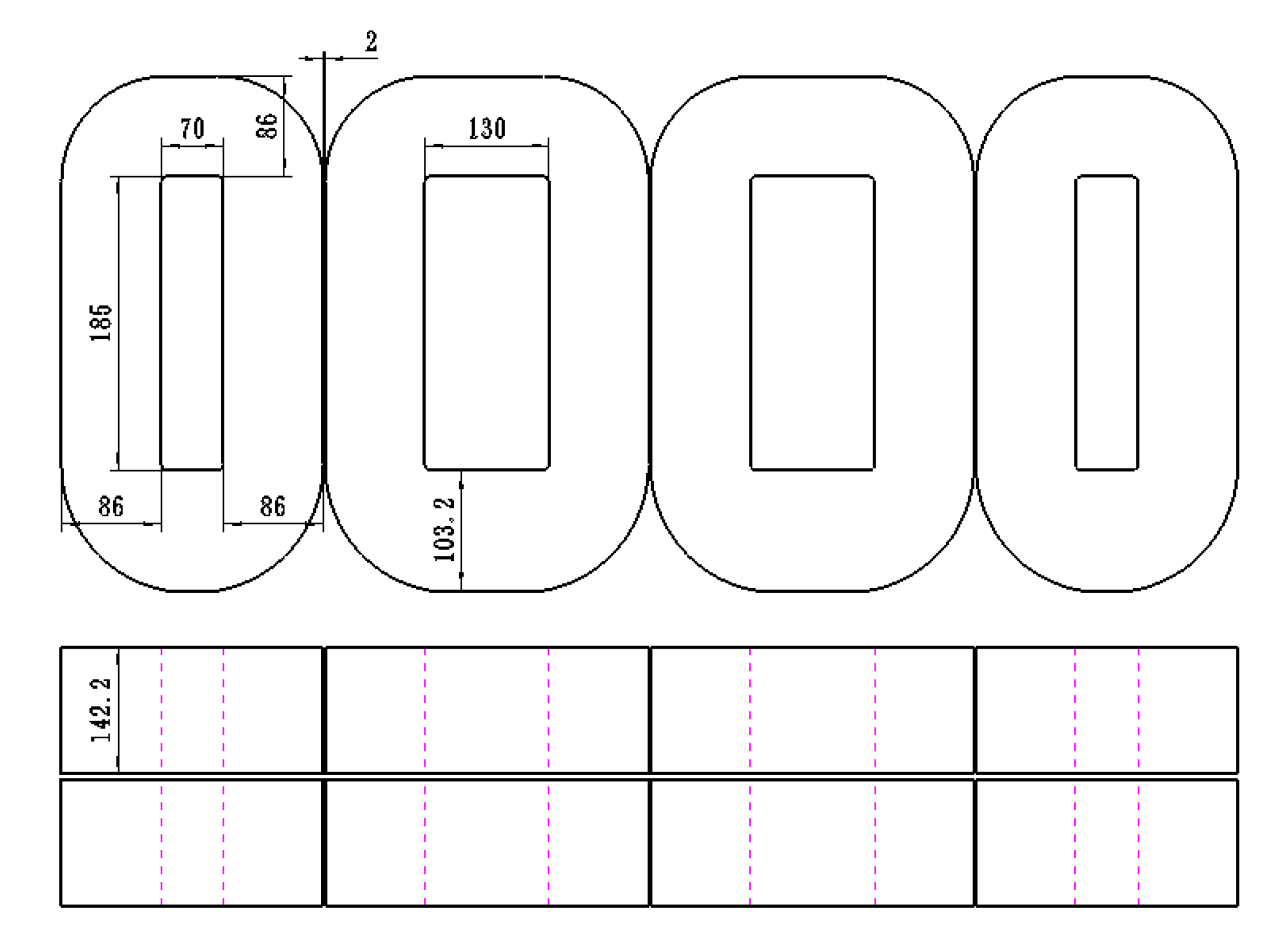
The core of SBH15-M 10 kV amorphous alloy distribution transformer is made of FA24S07-86 amorphous alloy produced by Antai Nanrui Amorphous Technology Co., Ltd. The core structure has three phases, four frames, and five columns (Figure 4) and the core structure parameters are shown in Table 2. Core material properties can be seen in Table 3.
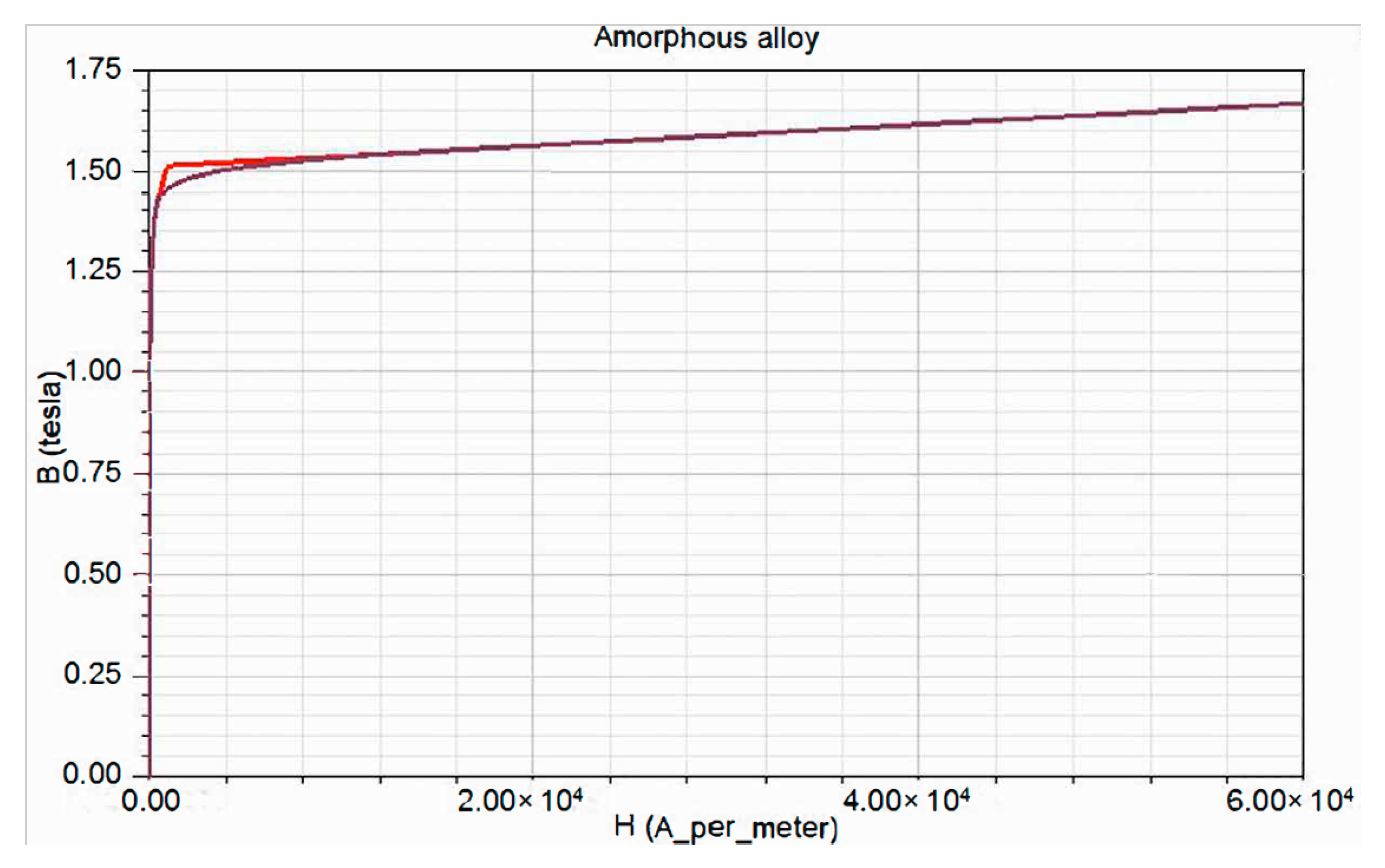
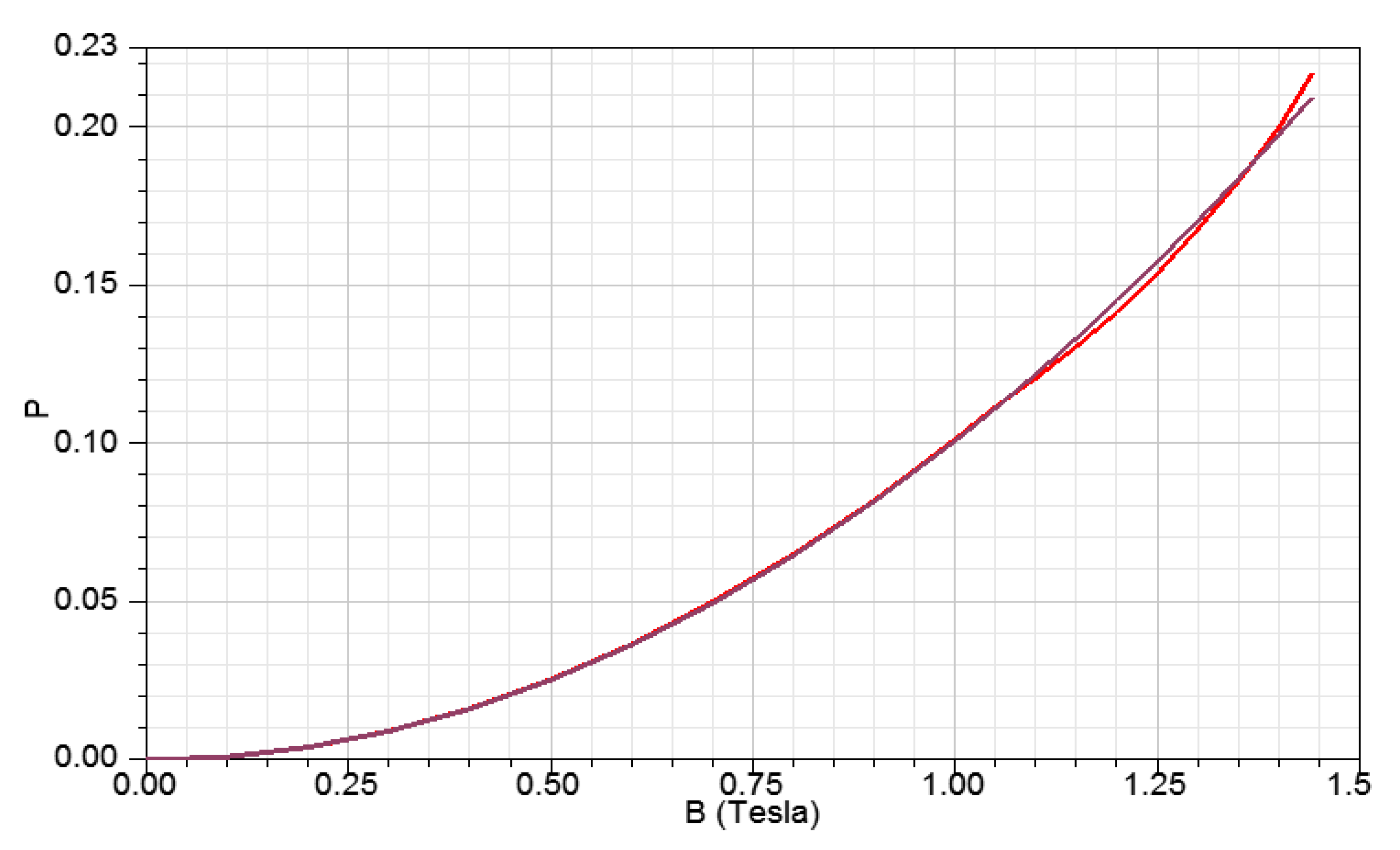
Figure 5 shows the magnetization curve of the amorphous alloy, and Figure 6 shows the iron loss curve of the amorphous alloy. The red lines in the two figures are the data entered by the authors, and the black lines are the curves fitted for the core material by ANSYS according to the data entered by the user. In order to accurately simulate the loss characteristics of amorphous alloy cores, the thickness of the material is set to 24 m, and the lamination factor is 0.86.

3.3. Winding

Since the core cross section of the amorphous alloy transformer is rectangular, in order to make the structure compact, the winding interface of the amorphous alloy is also rectangular. The high-voltage winding of the SBH15-M 10 kV amorphous distribution transformer is a three-layer cylindrical structure, and the low-voltage winding is a foil winding. Since the amorphous alloy is particularly sensitive to mechanical stress, the winding is not attached to the core during assembly. In order to prevent a major impact on the iron core from the short circuit of the winding, there is a certain gap between the winding and the iron core, and the gap is filled by the laminate, which can minimize the impact of the deformation of the iron core when a short circuit occurs.
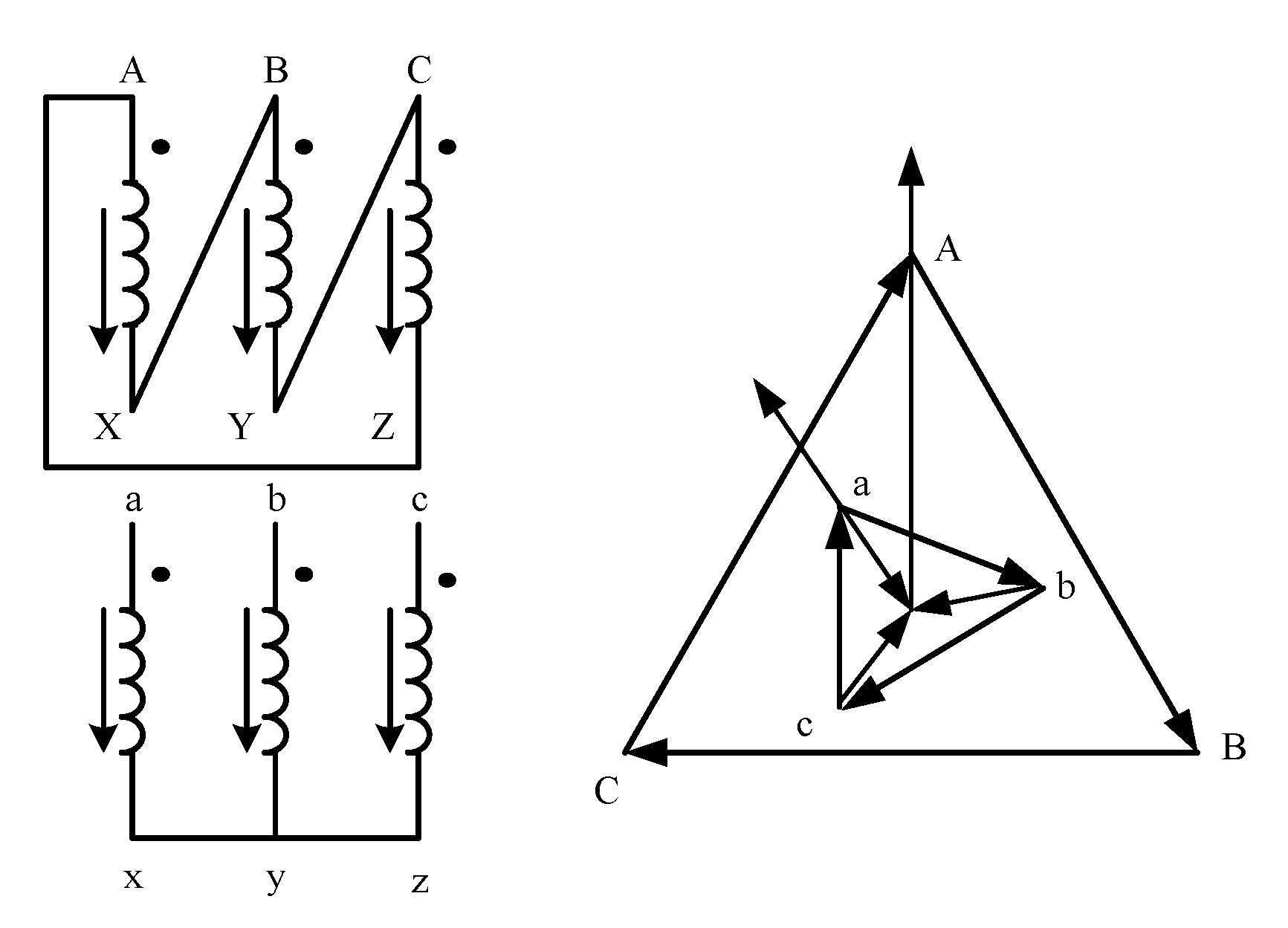
The connection group of the winding is Dyn11. As shown in Figure 7, the third harmonic can form a loop in the high-voltage side delta winding, so that there is no third harmonic voltage component in the secondary side voltage. The harmonic causes extra AC loss [25] and therefore harmonics should be minimized.
Winding parameters are shown in Table 4.

3.4. Meshing

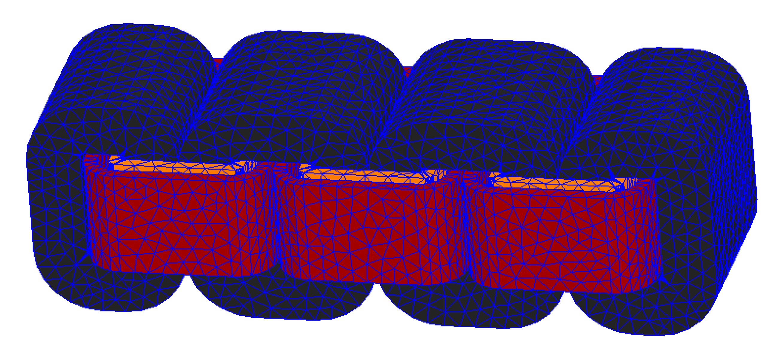
In this paper, a meshing method combining manual and adaptive methods is used. A manual meshing method is used for the core and windings, and only the maximum distance of the meshing unit is set (37.42 mm for core and 41.2 mm for winding). The meshing result is shown in Figure 8.

3.5. Electromagnetic-Circuit Coupling

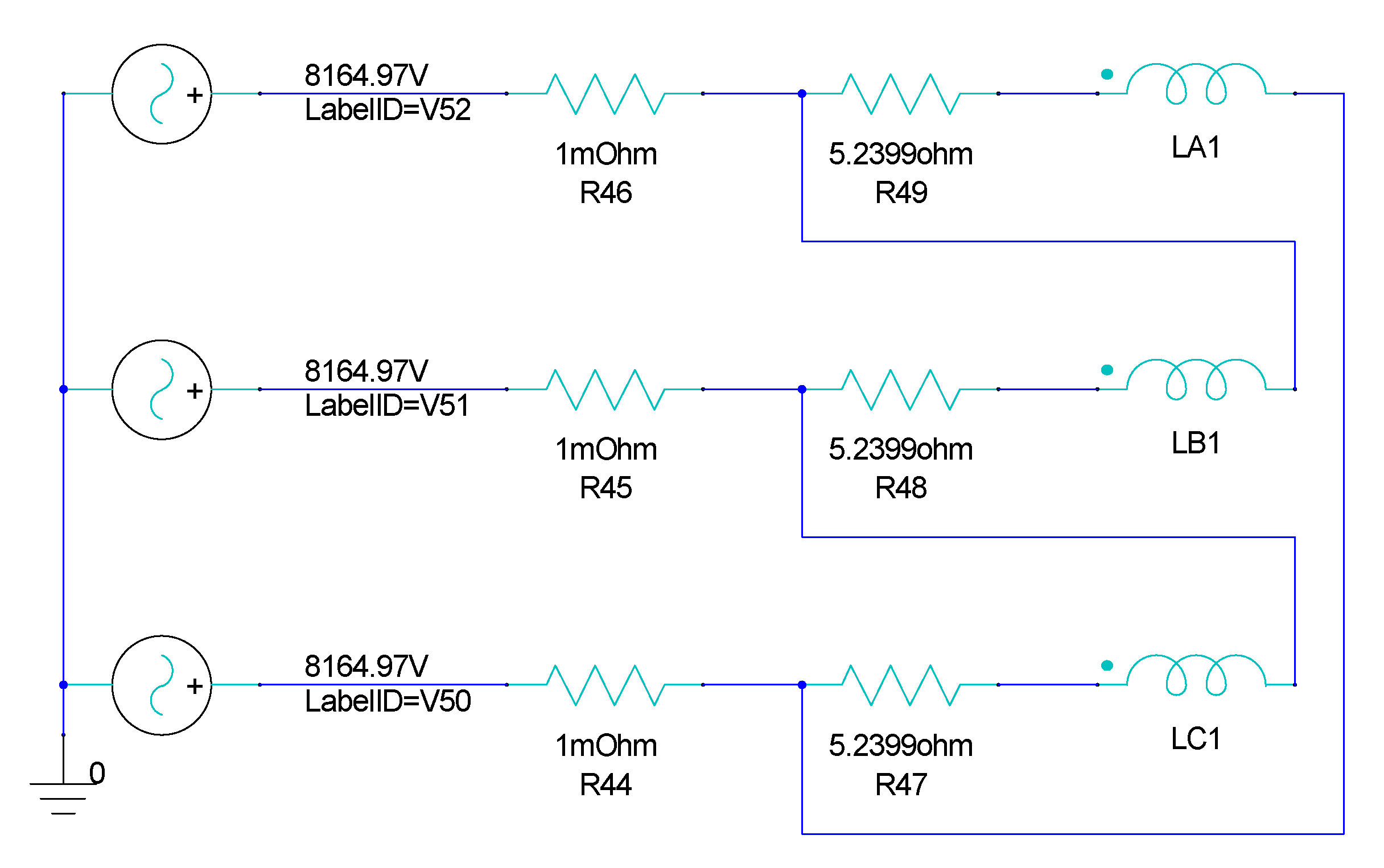
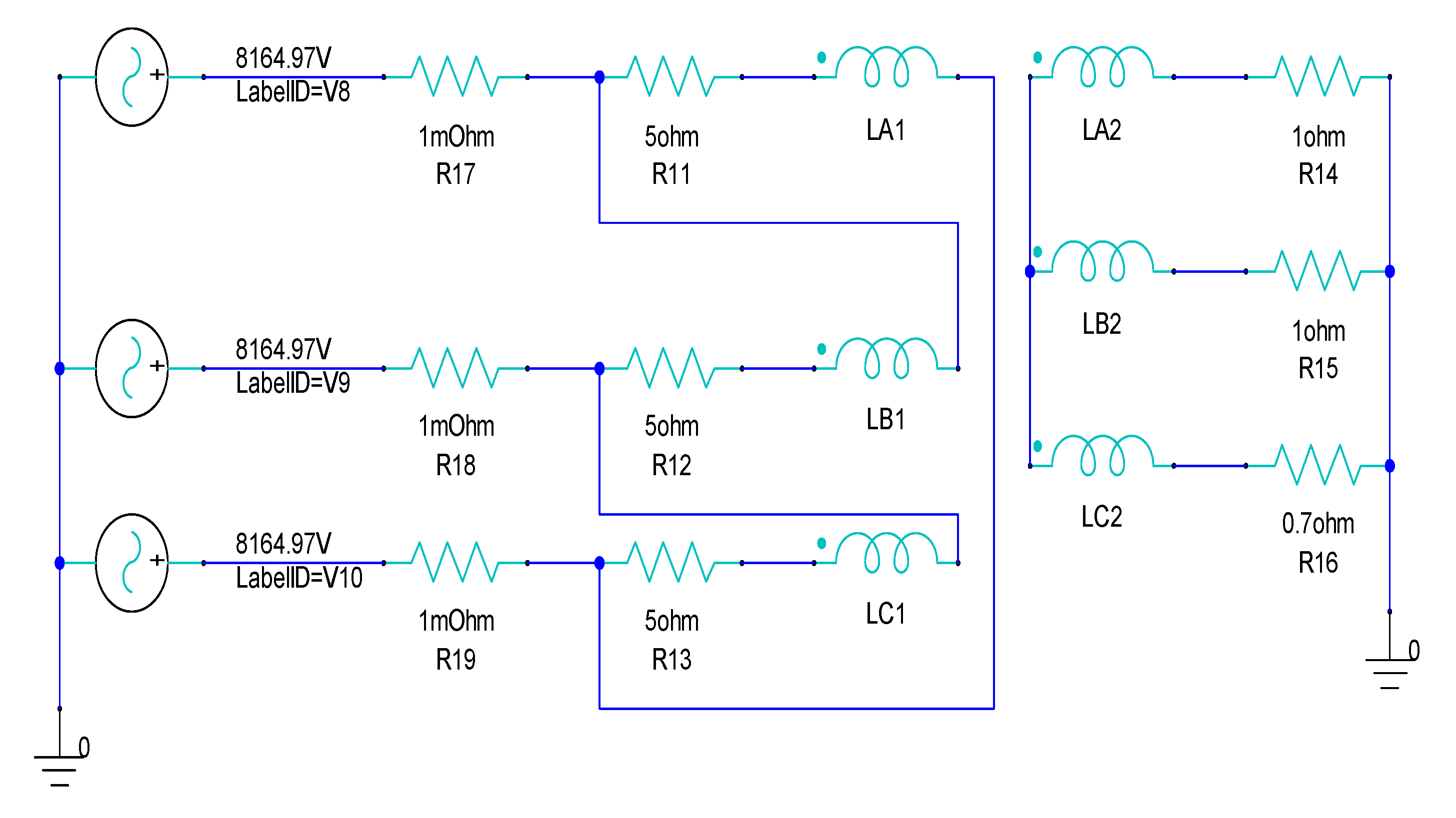
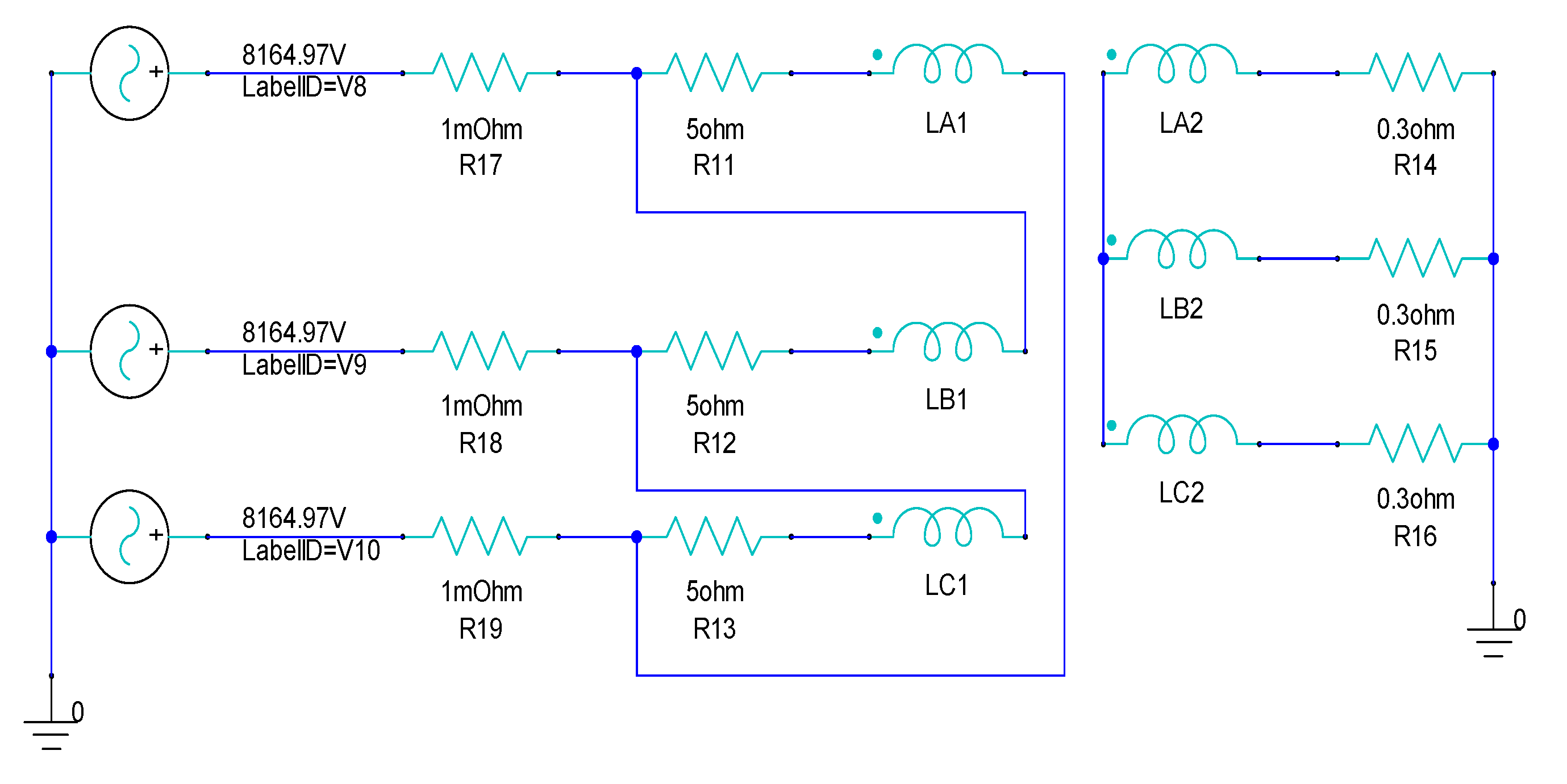
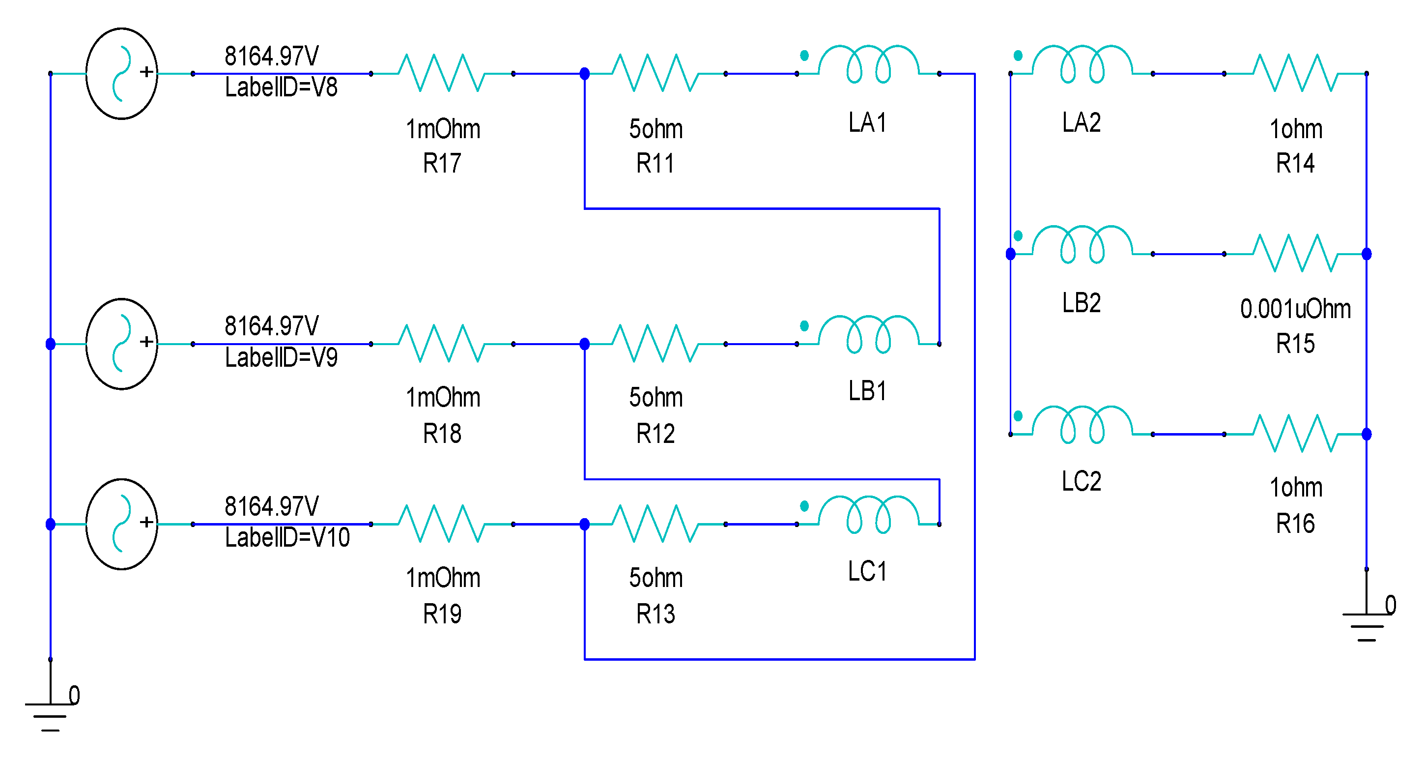
According to the connection group of transformers, the Dyn11 type is adopted, and a triangular connection method is adopted at the power supply side. The terminal on the power supply side is set through Maxwell field coupling and connected to the transformer winding in the simulation model during editing. The primary resistance in the excitation circuit is 5.2399 Ω. To prevent the software from iteration error by using a Norton equivalent circuit in the calculation, a very small resistance of 1 mΩ is added to the power supply. The excitation circuit model corresponding to the simulation model is shown in Figure 9.
As secondary side, active power output by three-phase transformer:
P = P a + P b + P c
Secondary phase voltage:
U = 231 V = U a = U b = U c
The phase current is Ia, Ib, Ic. Then active power per phase:
{ P a = U a I a cos β P b = U b I b cos β P c = U c I c cos β
If circuit is a pure resistive load, then cosβ = 1.
Load factor is:
η = P 315 × 100 %
1.
Normal load
Considering that amorphous alloy transformers are mostly used in the distribution network, the load rate is generally 30~60%. In this study, a 1 Ω load being added (η = 50%), the transformer windings and the load are connected to the three-phase power supply.
2.
Load imbalance
Phase A and Phase B add 1 Ω load, and Phase C adds 0.7 Ω load. Pa = 53.3 kVA, Pb = 53.3 kVA, Pc = 76.2 kVA. With the gradual decrease of phase C resistance, phase C active power gradually increases, and the load becomes more unbalanced. When the resistance drops to 0, a short circuit occurs.
3.
Overload
0.3 Ω loads have been added to simulate the overload situation of the transformer during operation (η = 169%).
4.
Short circuit
Setting the three-phase loads to 1 Ω, 1 × 10⁻⁹ Ω, and 1 Ω, respectively, a single-phase short circuit occurs. The very small resistance of phase B is equivalent to short-circuit.

4. Verification of Transformer Model

In order to verify the correctness of the finite element model of amorphous alloy transformers established in this paper, the simulation data are compared with experimental data. No-load current and no-load loss are selected for verification, so that the electromagnetic characteristics and the loss characteristics of the transformer can be verified. Since the secondary winding of the transformer is unloaded, the current of the secondary winding can be set to zero, which not only simulates the actual unloaded condition of the transformer accurately, but also makes the excitation circuit simpler.

4.1. No-Load Current

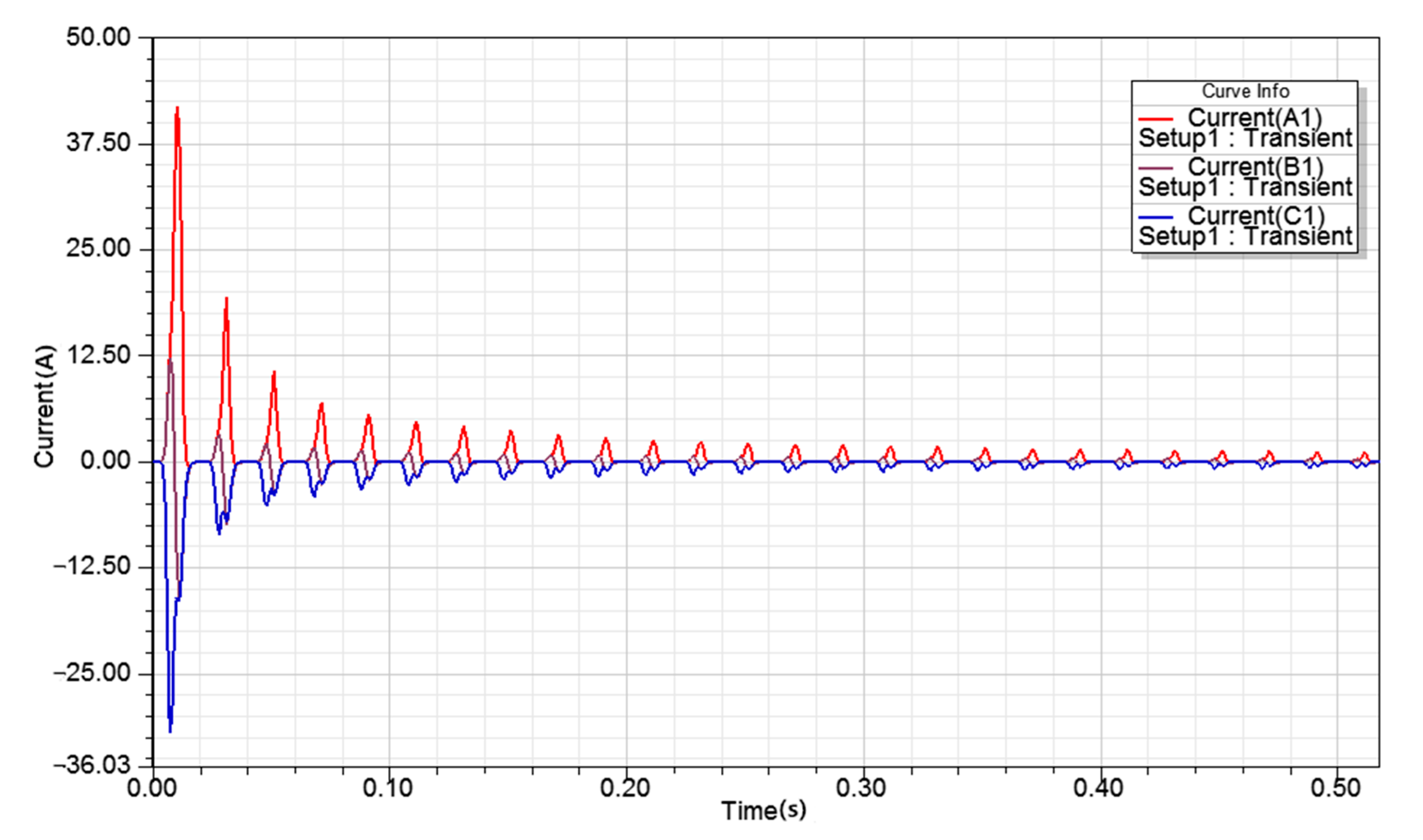
Circuit excitation (Figure 9) is connected with transformer model to realize joint simulation of electromagnetic field and circuit. The simulated no-load current is shown in Figure 10.
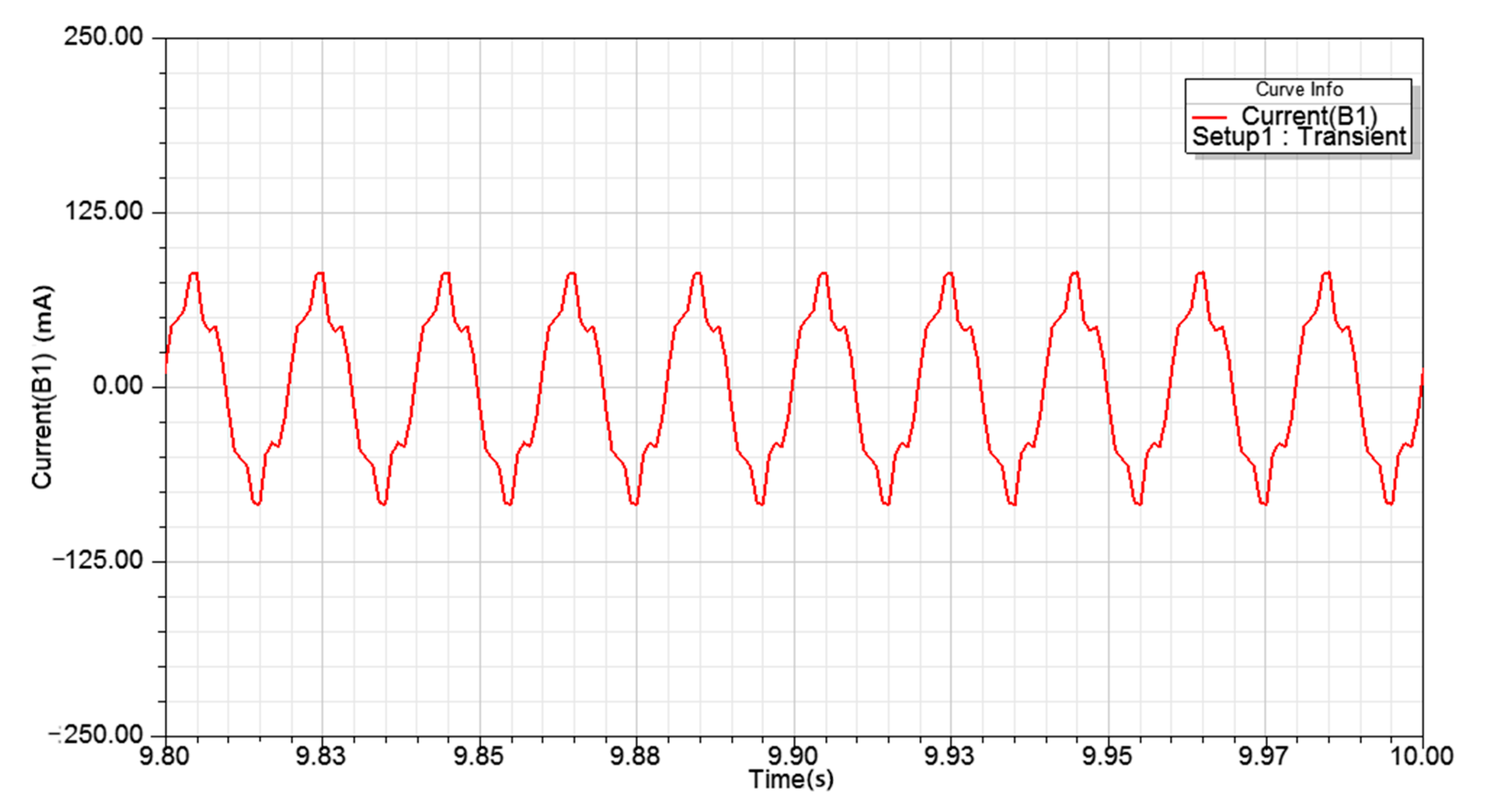
From the simulation results, it can be seen that the maximum excitation phase current of the transformer can reach 41.844 A, and the peak value of rated phase current on the primary side of the 10 kV amorphous alloy distribution transformer of SBH15-M type is 14.681 A. The maximum excitation phase current can reach 2.81 times the rated current, which is consistent with the fact that when the secondary winding is unloaded, the primary magnetic potential will have a large amplitude at the beginning. At this time, the amorphous alloy core is in the saturation region, the permeability is very small, and there will be a high unloaded current. After a period of time, the no-load current tends to stabilize, taking phase B current, as shown in Figure 11. It can be seen that the amplitude of the transformer tends to be stable after a period of time, but the current waveform is not completely sine wave, which is due to the hysteresis characteristic of the transformer core. When the transformer is unloaded, the current is almost completely used for excitation, and the influence of hysteresis characteristic will appear, causing current fluctuation. The peak value of no-load phase current at steady state is 82.295 mA, the percentage of no-load current is 82.295/14.681.

4.2. No-Load Loss

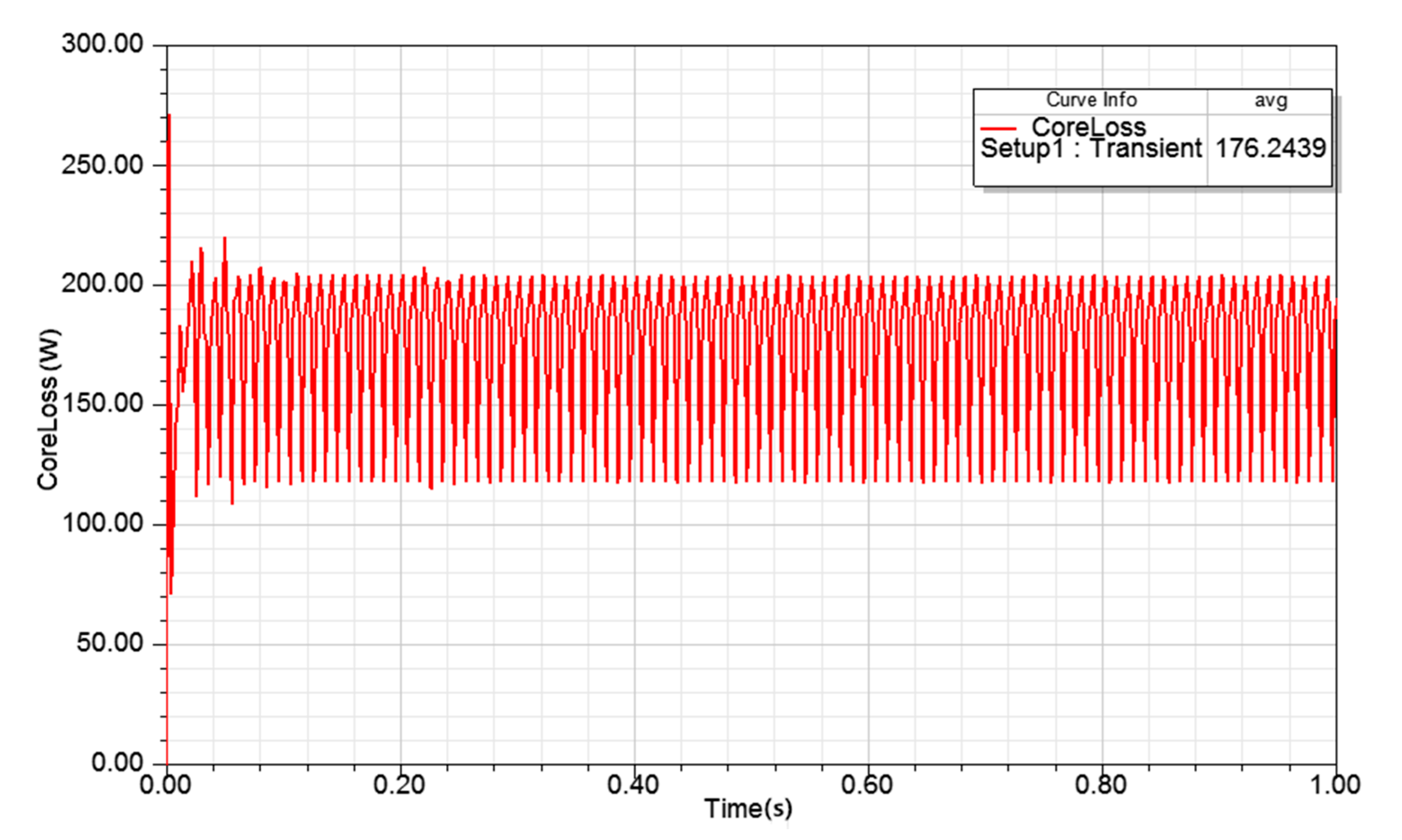
Circuit excitation (Figure 9) is connected with transformer model to realize joint simulation of circuit and electromagnetic field. The simulated no-load loss is shown in Figure 12.
From the simulation results, it can be seen that the average no-load loss of the transformer is 176.2439 W when it is stable, and the actual product field test no-load loss data are 170 W, with a difference of 3.67%, which again shows good agreement with the simulation (provided by Shandong Zhixin Intelligent Equipment Co. Ltd.).
The finite element model of the amorphous alloy transformer established in Section 3 has a no-load current and no-load loss which are similar to the field test data of the product when the secondary winding is in no-load operation, and the data error is relatively small. Therefore, it can be verified that the model established in this paper is practical and it is feasible to ignore the influence of transformer oil in electromagnetic field simulation.
The paper provides a means to minimize the core loss for high power transformers and the associated harmonics studied in the core analysis. It notes the application for rail systems and other power distribution. It is expected that using the proposed study, electromagnetic emission and loss can be improved.

5. Simulation Analysis of Iron Core Electromagnetic Field and Strain under Different Working Conditions

5.1. Normal Load

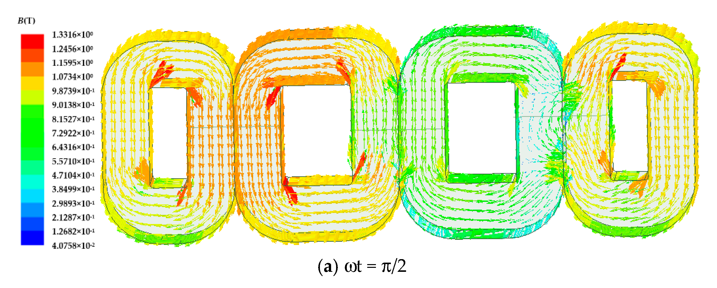
The excitation circuit for electromagnetic field simulation is shown in Figure 13, and the magnetic field distribution in the core of the amorphous alloy transformer during normal operation can be obtained [16].
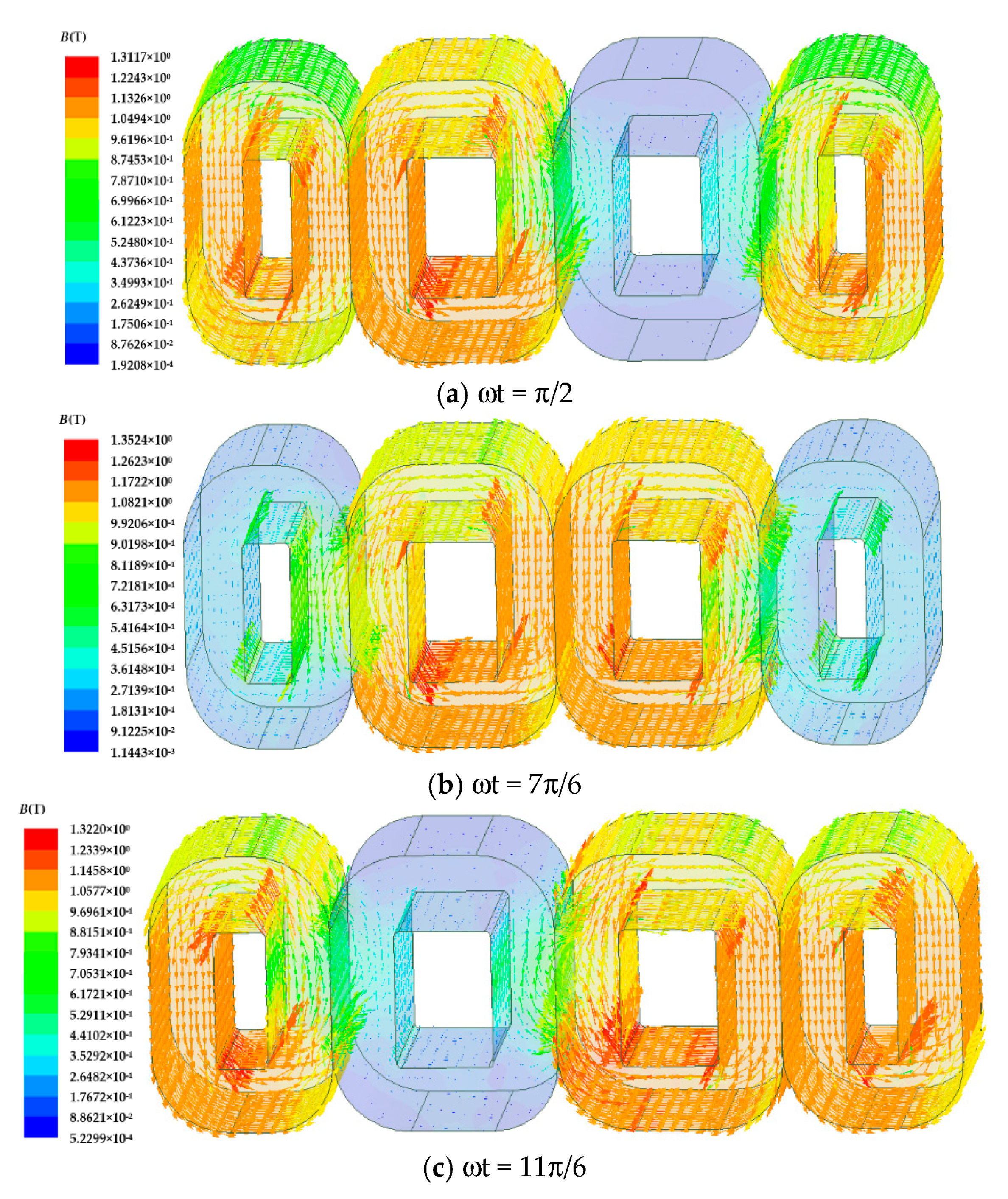
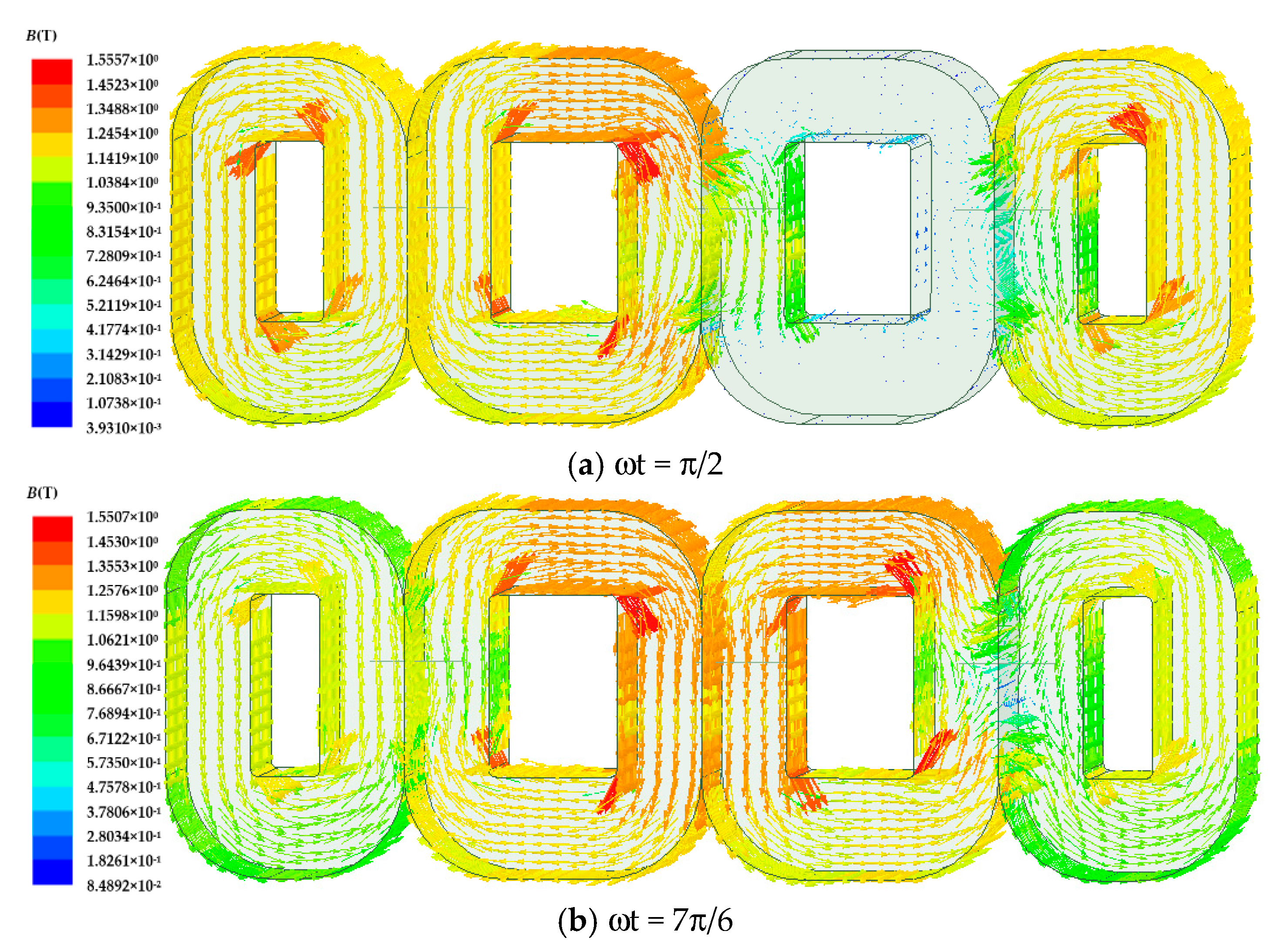
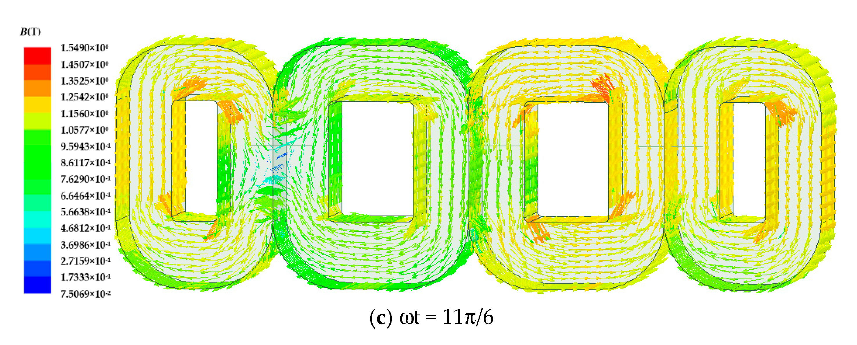
Figure 13 shows the magnetic induction intensity vector distribution when the three-phase magnetic fluxes of A, B, and C reach their maximums.
It can be seen from Figure 14 that the three-phase magnetic flux lags by 2/3 when it reaches the maximum. The magnetic induction intensity of the transformer core column and iron yoke is about 1.34 T, basically working in the linear working area of the magnetization curve, which is the normal working range of the transformer. The magnetic field simulation results show that the transformer’s magnetic field changes sinusoidally under the excitation of a three-phase voltage source. The test maximum magnetic induction intensity of the actual product is 1.348 T (provided by Shandong Zhixin Intelligent Equipment Co. Ltd.). Thus, this model can accurately simulate the magnetic field distribution of the SBH15-M 10 kV amorphous alloy distribution transformer.
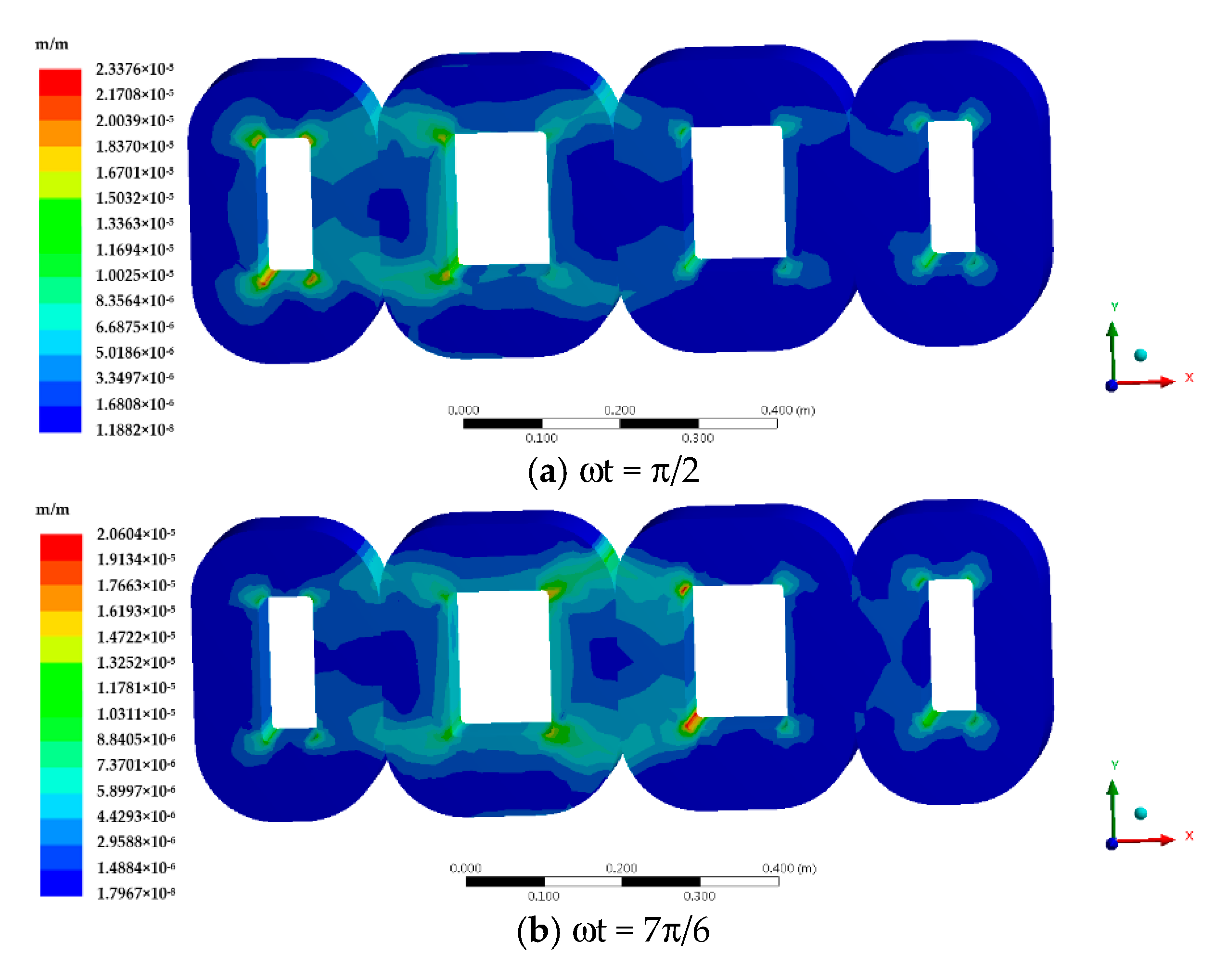
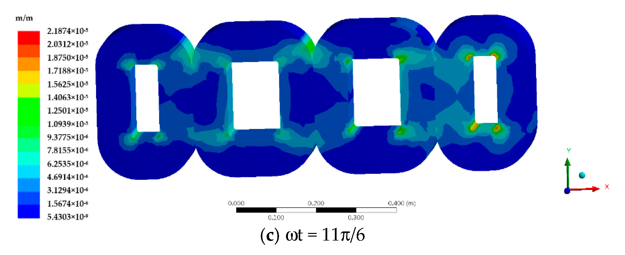
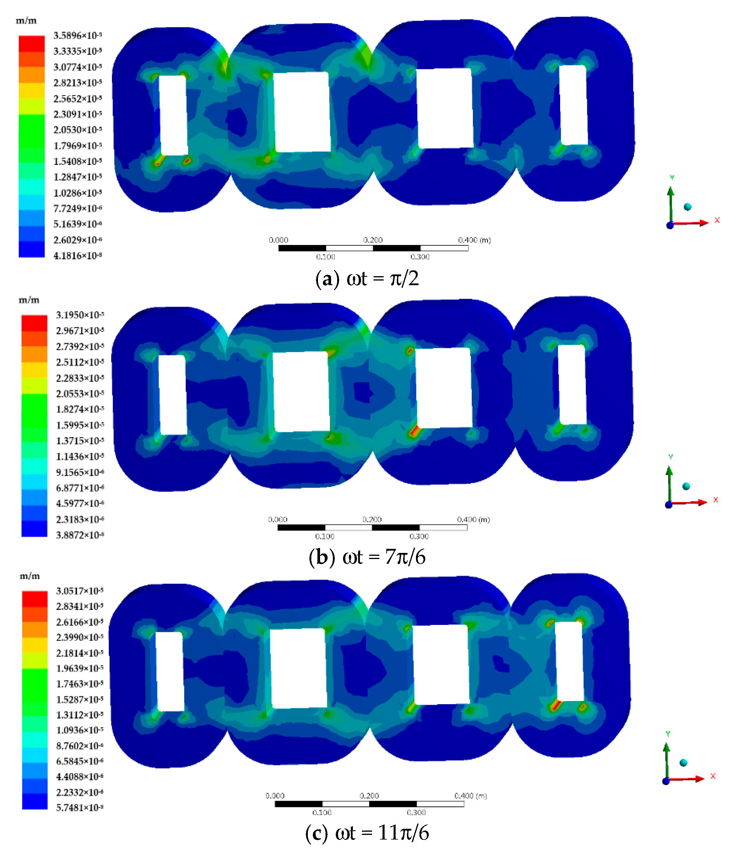
Figure 15 shows the strain cloud diagram of the amorphous alloy core caused by magnetostriction when the three-phase magnetic flux reaches the maximum in the normal operation of the amorphous alloy transformer.
It can be seen that the strain caused by magnetostriction is mainly concentrated at the corner where the iron core column and the iron yoke intersect, which is consistent with the distribution of the magnetic induction intensity in Figure 15, and the maximum strain is 2.3376 × 10⁻⁵ m/m.

5.2. Load Imbalance

The excitation circuit for electromagnetic field simulation is shown in Figure 16.
The magnetic field distribution of the transformer core model is shown in Figure 17 when the load is unbalanced.
Figure 18 shows the strain cloud diagram of the amorphous alloy core caused by magnetostriction when the load is unbalanced.
Further reducing the resistance of the C, the stress situation in a more unbalanced state is explored as shown in Table 5.
As the load becomes more unbalanced, the strain of the iron core gradually increases. When a short circuit occurs, the strain of the iron core reaches the maximum.

5.3. Overload

The excitation circuit is shown in Figure 19.
The magnetic induction intensity vector distribution of the transformer core model when there is overload is shown in Figure 20.
Figure 21 shows the strain cloud diagram of overload of transformer core caused by magnetostriction in the overload situation.
We reduce the resistance of the three phases at the same time, and simulate the iron core stress under different overload conditions as shown in Table 6.
Under normal circumstances, as the load increases, the stress of the iron core increases. When the transformer is overloaded, the core stress increases faster. The maximum value is higher than the core stress during C-phase short circuit.

5.4. Short Circuit

Figure 22 shows the excitation circuit.
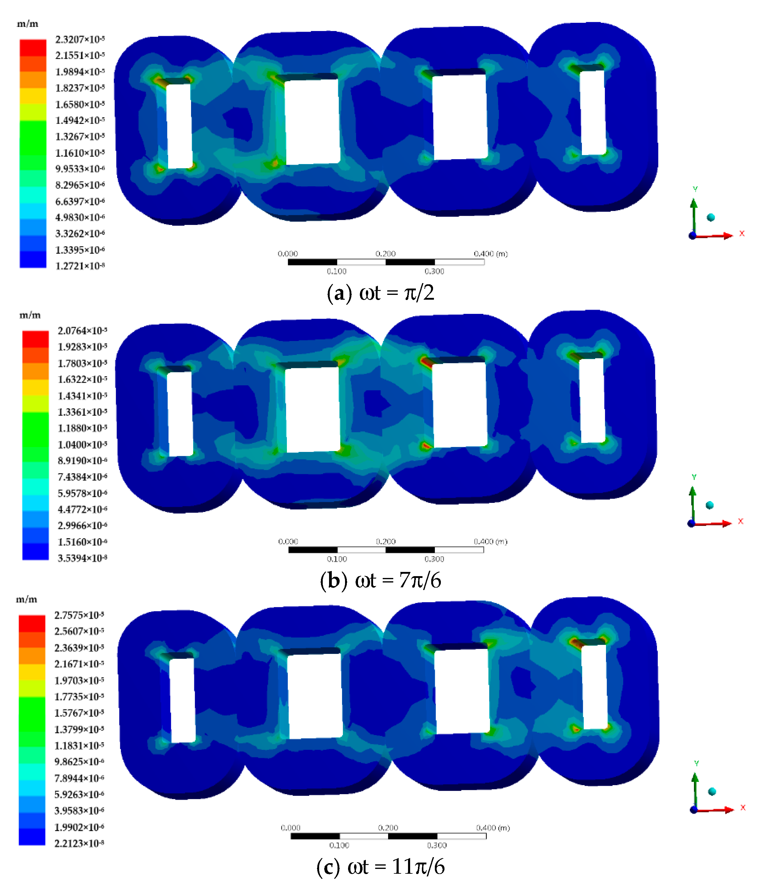
The magnetic induction intensity vector distribution of the transformer core model when a short circuit occurs on the secondary side is shown in Figure 23.
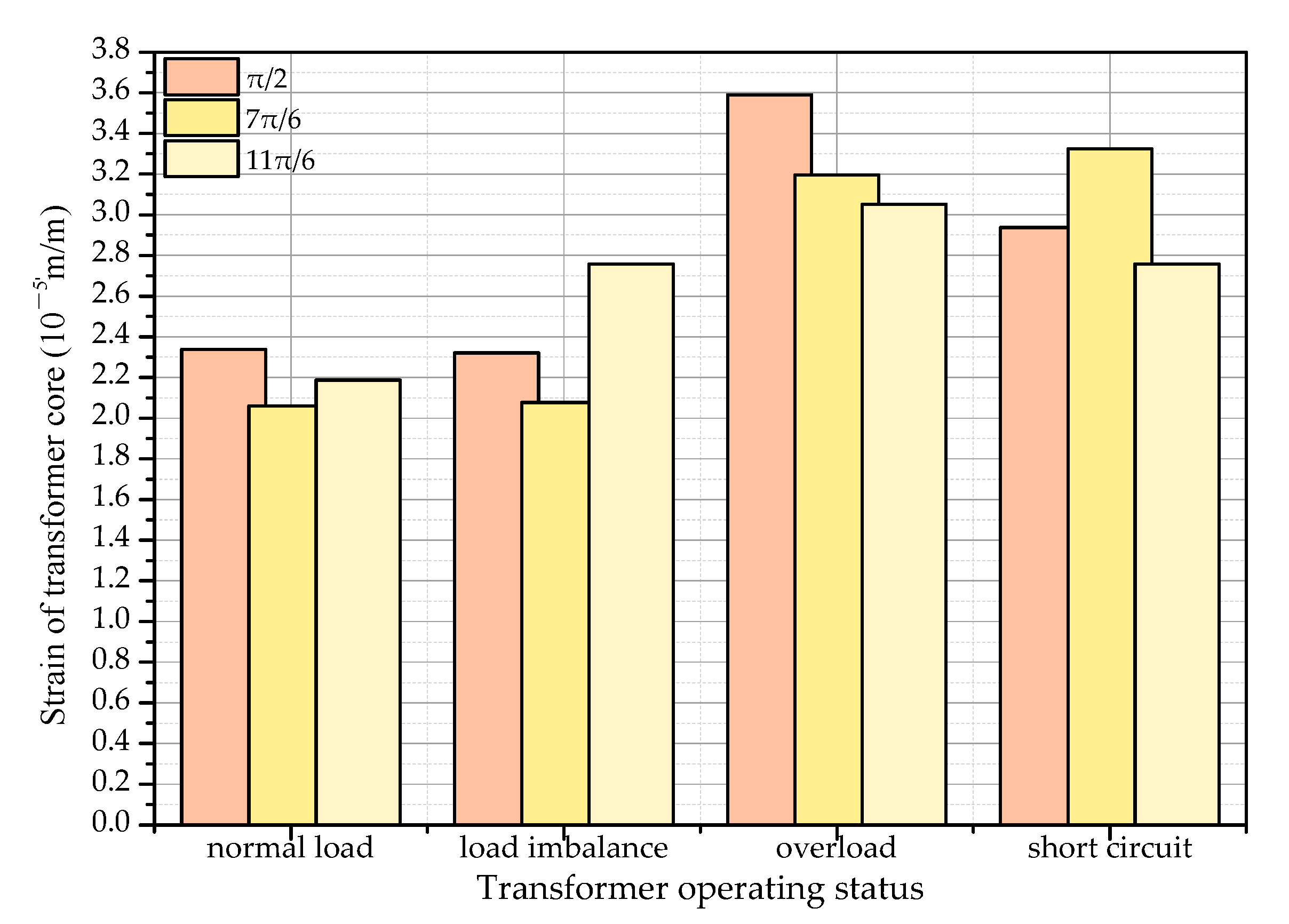
Figure 24 shows the strain cloud diagram of overload of transformer core caused by magnetostriction when a short circuit occurs. The maximum value of strain at 11π/6 is 2.76 × 10⁻⁵, which is less than C-phase short circuit and overload situation. The core strain caused by the side-phase short circuit is larger than the middle-phase short circuit.
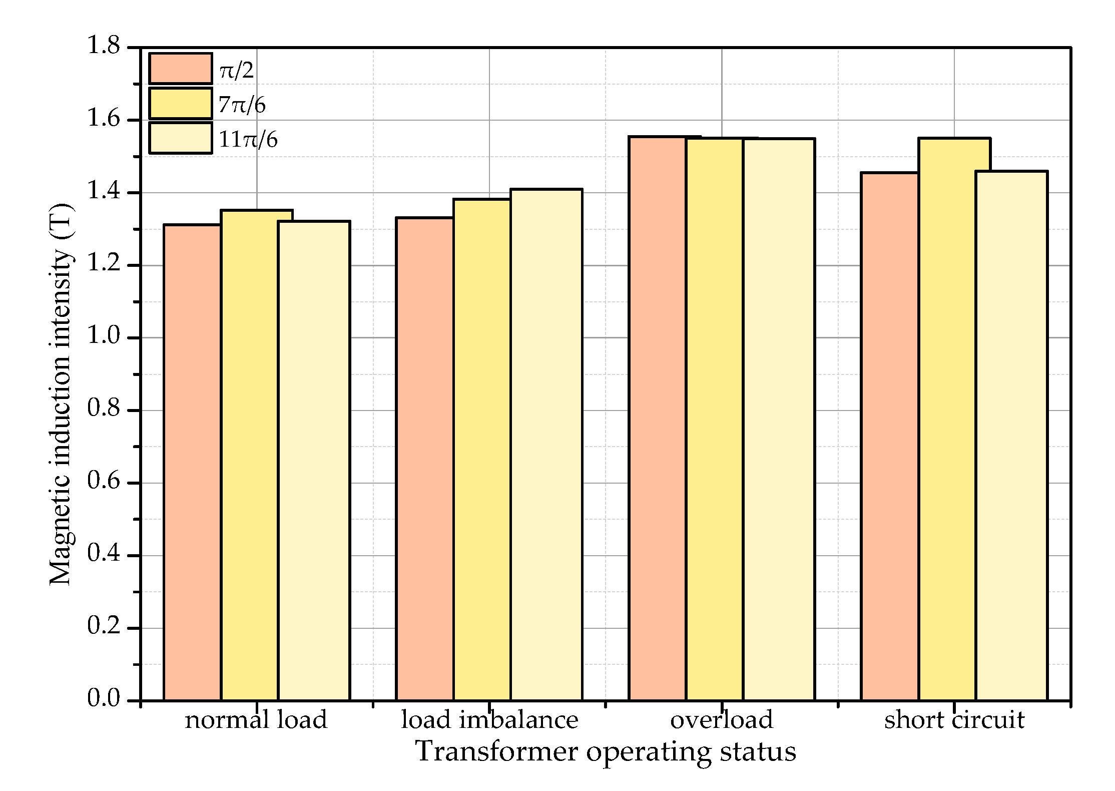
Figure 25 and Figure 26 show the maximum values of magnetic induction and strain of transformer core, respectively, in the four operating modes (Section 3.5) when the three-phase magnetic fluxes of A, B, and C reach their maximums.
It can be seen from Figure 25 and Figure 26 that under load imbalance, overload, and short-circuit conditions, the magnetic induction intensity of the transformer core and the strain caused by magnetostriction both increase. The biggest influence on the iron core is the overload state, and the average stress is 49.37% higher than that under normal operation. In the short-circuit state, the average stress increased by 36.93%. Load imbalance has little effect on the transformer core strain.

6. Discussion

In this paper, the physical model of the SBH15-M 10 kV amorphous alloy distribution transformer is established, the model being reasonably divided, and the no-load current simulation and no-load loss simulation verifying the correctness of the model. A mathematical model of the electromagnetic field-mechanical field coupling of the amorphous alloy core is established, and the electromagnetic field distribution and the strain under the influence of the magnetostrictive characteristics of the transformer under different working conditions are analyzed.
When a transformer or core with a different structure or characteristics is used, the force result will change, but the conclusion will not be affected, because the electromagnetic field law applying to the core is the same under the same working conditions.
The results of the model provide a certain basis and reference for calculating the force of the iron core under different working conditions, optimizing transformer design, and providing technical support for the integration of amorphous alloy transformers.
However, the simulation model in this paper was established after proper simplification. Only the simulation research of amorphous alloy transformer cores under different working conditions was carried out, and it was not strongly combined with the experiment. In addition, this paper does not analyze the debris generated under stress. Further research can be carried out on the following aspects:
  • Combining the simulation analysis results with the experiment and testing the stress of the iron core under different working conditions;
  • Calculating the amount of amorphous debris generated under stress by simulation;
  • Studying the flow trajectory and distribution of the amorphous debris in the transformer oil after generation;
  • Studying detailed strain analysis under different overloads and load imbalance, and its effect during high-speed rail operation.

7. Conclusions

The work done and the conclusions obtained are as follows:
  • A strong coupling theory of electromagnetic field and mechanical field for magnetostriction of amorphous alloys and an actual calculation model of indirect coupling method using interpolation are proposed.
  • The finite element model of the amorphous alloy transformer established has no-load current and no-load loss, similar to the field test data of the product when the secondary winding is in no-load operation, and the data error is relatively small.
  • The normal operation of amorphous alloy transformers is simulated, and the characteristics of electric field, magnetic field, and eddy current field are analyzed. During normal operation, the electromagnetic characteristics of the transformer conform to the actual situation, which verifies the correctness of the simulation.
  • As the load becomes more unbalanced, the strain of the iron core gradually increases. When a short circuit occurs, the strain of the iron core reaches the maximum. Under normal circumstances, as the load increases, the stress of the iron core increases. When the transformer is overloaded, the core stress increases faster and the maximum value is higher than the core stress during C-phase short circuit.

Author Contributions

Conceptualization, C.X. and K.W.E.C.; methodology, J.S.; software, J.S.; validation, J.S.; formal analysis, J.S. and C.X.; investigation, J.S.; resources, K.W.E.C. and C.X.; data curation, J.S.; writing—original draft preparation, J.S.; writing—review and editing, C.X. and K.W.E.C.; visualization, C.X.; supervision, K.W.E.C. and C.X.; project administration, C.X.; funding acquisition, K.W.E.C. All authors have read and agreed to the published version of the manuscript.

Funding

This research was funded by the Hong Kong Branch of National Rail Transit Electrification and Automation Engineering Technology Research Centre, grant number BBVR.

Acknowledgments

We would like to thank Yake Tang, Hong Huang, and Shandong Zhixin Intelligent Equipment Co. Ltd. for the assistance in technical support.

Conflicts of Interest

The authors declare no conflict of interest.

References

  1. Shao, J.; Wang, J.; Long, M.; Li, J.; Ma, Y. 5000 h Multi-Factor Accelerated Aging Test of FRP Made Transmission Tower: Characterization, Thermal Decomposition and Reaction Kinetics Study. Polymers 2017, 9, 170. [Google Scholar] [CrossRef] [PubMed] [Green Version]
  2. Wang, J.; Shao, J.; Long, M.; Ma, Y.; Liu, K. Multifactor mechanical aging properties and electrical performance research on composite material tower and samples. IEEE Trans. Electr. Electron. Eng. 2018, 13, 13–26. [Google Scholar] [CrossRef]
  3. Zhao, Y.; Zheng, J.; Zhang, Z.; Shi, D.; Qin, X. Study on the influence of amorphous debris on the electric field of amorphous alloy transformer in urban rail transit. In 2017 2nd International Conference on Power and Renewable Energy (ICPRE), Proceedings of the 2017 2nd International Conference on Power and Renewable Energy (ICPRE), Chengdu, China, 20–23 September 2017; IEEE: Piscataway Township, NJ, USA, 2017; pp. 1–5. [Google Scholar] [CrossRef]
  4. Sima, W.; Zou, M.; Yang, M.; Yang, Q.; Peng, D. Modeling of grain-oriented Si-steel and amorphous alloy iron core under ferroresonance using Jiles–Atherton hysteresis method. AIP Adv. 2018, 8, 056608. [Google Scholar] [CrossRef]
  5. Li, T.; Zhang, Y.; Liang, Y.; Ai, Q.; Dou, H. Multiphysics Analysis of an Axial-Flux In-Wheel Motor with an Amorphous Alloy Stator. IEEE Access 2020, 8, 27414–27425. [Google Scholar] [CrossRef]
  6. Alexandrov, N.; Schulz, R. Roberge Amorphous Alloys for Distribution Transformers: Design Considerations and Economic Impact. IEEE Trans. Power Deliv. 1987, 2, 420–424. [Google Scholar] [CrossRef]
  7. Bykovskaya, L.V.; Bykovskiyi, V. Simulation of a Voltage Transformer with a Magnetic Core Made of Amorphous Steels. In Proceedings of the 2020 International Conference on Industrial Engineering, Applications and Manufacturing (ICIEAM); Institute of Electrical and Electronics Engineers (IEEE): Piscataway Township, NJ, USA, 2020; pp. 1–5. [Google Scholar]
  8. Zheng, J.; Zhao, Y.; Zhang, Z.; Shi, D.; Qin, X. Study on the influence of amorphous debris on the magnetic field distribution of amorphous alloy transformer. In Proceedings of the International Conference on Power and Renewable Energy (ICPRE), 2nd ed.; Institute of Electrical and Electronics Engineers (IEEE): Piscataway Township, NJ, USA, 2017; pp. 126–131. [Google Scholar]
  9. Liu, D.; Li, J.; Wang, S.; Yang, S.; Lin, Y.; Qi, Z.; Yan, M. Stability of Properties on Magnetic Ribbon and Cores with Domestic Fe-Based Amorphous Alloy for HTS AMDT. IEEE Trans. Appl. Supercon. 2019, 29, 1–5. [Google Scholar] [CrossRef]
  10. Takahashi, K.; Azuma, D.; Hasegawa, R. Acoustic and Soft Magnetic Properties in Amorphous Alloy-Based Distribution Transformer Cores. IEEE Trans. Magn. 2013, 49, 4001–4004. [Google Scholar] [CrossRef]
  11. Du, B.X.; Liu, D.S. Dynamic Behavior of Magnetostriction-Induced Vibration and Noise of Amorphous Alloy Cores. IEEE Trans. Magn. 2015, 51, 1–8. [Google Scholar] [CrossRef]
  12. Liu, D.; Du, B.; Yan, M.; Wang, S. Suppressing Noise for an HTS Amorphous Metal Core Transformer by Using Microperforated Panel Absorber. IEEE Trans. Appl. Supercon. 2016, 26, 1–5. [Google Scholar] [CrossRef]
  13. Liu, X.; Wang, Y.; Zhu, J.; Guo, Y.; Lei, G.; Liu, C. Calculation of core loss and copper loss in amorphous/nanocrystalline core-based high-frequency transformer. AIP Adv. 2016, 6, 055927. [Google Scholar] [CrossRef] [Green Version]
  14. Haifeng, Z.; Wenhao, N.; Tao, L.; Dong, H.; Guoqiang, Z. The analysis of short-circuit withstanding ability for a 800 KVA/10 KV shell-form power transformer with amorphous alloy cores. In Proceedings of the 2012 China International Conference on Electricity Distribution; Institute of Electrical and Electronics Engineers (IEEE): Piscataway Township, NJ, USA, 2012; pp. 1–5. [Google Scholar]
  15. Guo, J.; Fang, S.; Zhang, Y.; Jin, Y. A novel method to check the axial tilt instability of the rectangular winding of the amorphous alloy transformer. IEEE Trans. Electr. Electron. Eng. 2018, 13, 92–97. [Google Scholar] [CrossRef] [Green Version]
  16. Xuan, M.; Du, X.; Xuan, L.; Hong, H. Analysis of production mechanism of amorphous debris in amorphous alloy transformer. Eng. J. Wuhan Univ. 2019, 52, 255–263. [Google Scholar]
  17. Xu, Y.; Wang, J.; Hou, H.; Shao, J. Simulation analysis of coupled magnetic-temperature fields in magnetic fluid hyperthermia. AIP Adv. 2019, 9, 105317. [Google Scholar] [CrossRef]
  18. Bahmani, M.A. Core Loss Calculation in Amorphous High Frequency High-Power Transformers with Different Topologies. Master’s Thesis, Chalmers University of Technology, Göteborg, Sweden, 2011. [Google Scholar]
  19. Chang, Y.-H.; Hsu, C.-H.; Chu, H.-L.; Tseng, C.-P. Magnetomechanical Vibrations of Three-Phase Three-Leg Transformer with Different Amorphous-Cored Structures. IEEE Trans. Magn. 2011, 47, 2780–2783. [Google Scholar] [CrossRef]
  20. Wu, S.; Tang, R.; Han, X.; Tong, W.; Zhao, S. Analytical Calculation and Influence Factors of Vibration in Amorphous Metal Cores. Trans. China Electrotech. Soc. 2016, 31, 73–82. [Google Scholar]
  21. Anderson, P.I.; Moses, A.J.; Stanbury, H.J. Assessment of the Stress Sensitivity of Magnetostriction in Grain-Oriented Silicon Steel. IEEE Trans. Magn. 2007, 43, 3467–3476. [Google Scholar] [CrossRef]
  22. Yan, R.G.; Yang, Q.X.; Yang, W.R.; Hou, S.P.; Yan, W.L. Giant Magnetostrictive Acceleration Sensors. Proc. Csee 2009, 29, 104–109. [Google Scholar]
  23. Besbes, M.; Ren, Z.; Razek, A. Finite element analysis of magneto-mechanical coupled phenomena in magnetostrictive materials. IEEE Trans. Magn. 1996, 32, 1058–1061. [Google Scholar] [CrossRef]
  24. Xue, X.; Cheng, K.W.E.; Bao, Y.J.; Leung, P.L.; Cheung, N.C. Switched Reluctance Generators with Hybrid Magnetic Paths for Wind Power Generation. IEEE Trans. Magn. 2012, 48, 3863–3866. [Google Scholar] [CrossRef]
  25. Cheng, K.W.E.; Evans, P.D. Calculation of winding losses in high frequency toroidal inductors using multi-strand conductors. IEE Proc. Electr. Power Appl. 1995, 142, 313–322. [Google Scholar] [CrossRef]
Figure 1. Research framework of the paper.
Energies 14 00164 g001
Figure 2. Magnetostrictive characteristic curve of amorphous alloy and silicon steel sheet.
Energies 14 00164 g002
Figure 3. SBH15-M 10 kV Amorphous Alloy Distribution Transformer.
Energies 14 00164 g003
Figure 4. Amorphous alloy core structure diagram.
Energies 14 00164 g004
Figure 5. Magnetization curve of amorphous alloy.
Energies 14 00164 g005
Figure 6. Iron loss curve of amorphous alloy.
Energies 14 00164 g006
Figure 7. Winding connection diagram.
Energies 14 00164 g007
Figure 8. Core and winding meshing results.
Energies 14 00164 g008
Figure 9. No-load driving circuit.
Energies 14 00164 g009
Figure 10. No-load current.
Energies 14 00164 g010
Figure 11. Steady-state no-load current.
Energies 14 00164 g011
Figure 12. No-load loss.
Energies 14 00164 g012
Figure 13. Excitation circuit during normal operation.
Energies 14 00164 g013
Figure 14. Magnetic induction intensity vector at different moments during normal operation.
Energies 14 00164 g014
Figure 15. Strain of transformer core caused by magnetostriction during normal operation.
Energies 14 00164 g015aEnergies 14 00164 g015b
Figure 16. Excitation circuit during load imbalance.
Energies 14 00164 g016
Figure 17. Magnetic induction intensity vector at different moments during load imbalance.
Energies 14 00164 g017aEnergies 14 00164 g017b
Figure 18. Strain of transformer core caused by magnetostriction during load imbalance.
Energies 14 00164 g018
Figure 19. Excitation circuit during overload.
Energies 14 00164 g019
Figure 20. Magnetic induction intensity vector at different moments during overload.
Energies 14 00164 g020aEnergies 14 00164 g020b
Figure 21. Strain of transformer core caused by magnetostriction during overload.
Energies 14 00164 g021
Figure 22. Excitation circuit during short circuit.
Energies 14 00164 g022
Figure 23. Magnetic induction intensity vector at different moments during short circuit.
Energies 14 00164 g023
Figure 24. Strain of transformer core caused by magnetostriction during short circuit.
Energies 14 00164 g024
Figure 25. Maximum values of magnetic induction in the four operating modes.
Energies 14 00164 g025
Figure 26. Maximum values of strain of transformer core in the four operating modes.
Energies 14 00164 g026
Table 1. SBH15-M 10 kV amorphous distribution transformer nameplate data.
Model NumberPhase NumberRated Voltage (kV)Join GroupsRated Capacity (kVA)Frequency (Hz)Rated Current (A)Tapping Range
SBH15-M310/0.4Dyn113155018.2/454.710 × (1 ± 2 × 2.5)
Table 2. Core structure parameters.
ParametersInner Frame Length (mm)Inner Frame Height (mm)Thickness (mm)Width (mm)
Big frame iron core18513086142.2
Small frame iron core1857086142.2
Table 3. Core material properties.
PerformanceSaturated Magnetic Induction (T)Lamination CoefficientResistivity (μΩm)Density (g/cm3)Young’s Modulus (GPa)Poisson RatioVickers Degree (HV)Thickness (m)
Size1.560.861.37.18-1100.390024
Table 4. SBH15-M 10 kV amorphous distribution transformer winding parameters.
WindingHigh-Voltage WindingLow-Voltage Winding
Turns81818
Sectional area (mm2)3.94152
Resistance (Ω)5.23990.002614
Rated current (A)18.2454.7
Materialred copperred copper
Winding connection modeDY
Sinusoidal voltage (kV)100.4
Table 5. Maximum values of strain in different unbalanced states.
Phase C (Ω)0.60.50.40.30.20.110−9
maximum values of strain at 11π/6 (10−5)2.782.812.852.902.932.952.99
Table 6. Maximum values of strain in different overload states.
η507090110130160
maximum values of strain at 11π/6 × (10−5)2.192.292.422.662.853.02
Publisher’s Note: MDPI stays neutral with regard to jurisdictional claims in published maps and institutional affiliations.