Article

A Study of the Electrical Output and Reliability Characteristics of the Crystalline Photovoltaic Module According to the Front Materials

1
Photovoltaic Laboratory, New and Renewable Energy Institute, Korea Institute of Energy Research, Daejeon 34129, Korea
2
General Administration Division, Strategy & Management Executive Director, Korea Energy Agency, Jung-gu, Ulsan 44538, Korea
*
Author to whom correspondence should be addressed.
Energies 2021, 14(1), 163; https://doi.org/10.3390/en14010163
Submission received: 28 October 2020 / Revised: 22 December 2020 / Accepted: 24 December 2020 / Published: 30 December 2020

Abstract

:
In recent years, various types of installations such as floating photovoltaic (PV) and agri-voltaic systems, and BIPV (building integrated photovoltaic system) have been implemented in PV systems and, accordingly, there is a growing demand for new PV designs and materials. In particular, in order to install a PV module in a building, it is important to reduce the weight of the module. The PV module in which low-iron, tempered glass is applied to the front surface, which is generally used, has excellent electrical output and reliability characteristics; however, it is heavy. In order to reduce the weight of the PV module, it is necessary to use a film or plastic-based material, as opposed to low-iron, tempered glass, on the front surface. However, if a material other than glass is used on the front of the PV module, various problems such as reduced electrical output and reduced reliability may occur. Therefore, in this paper, a PV module using a film instead of glass as the front surface was fabricated, and a characteristic analysis and reliability test were conducted. First, the transmittance and UV characteristics of each material were tested, and one-cell and 24-cell PV modules were fabricated and tested for electrical output and reliability. From the results, it was found that the transmittance and UV characteristics of the front material were excellent. In addition, the electrical output and reliability test results confirmed that the front-surface film was appropriate for use in a PV module.

1. Introduction

Photovoltaic (PV) power generation has received much attention because it is a clean energy source that does not pollute the environment. Recently, photovoltaic systems have not only been implemented on land, but also have various installation types such as floating PV systems, offshore, floating PV systems, agro-photovoltaic and the building integrated photovoltaic system (BIPV). In particular, the BIPV system can directly use the electricity produced because it is installed in buildings, and the number of BIPV installations continues to increase because it does not require a restrictive installation space [1,2]. In addition, the potential of BIPV continues to rise, and in the United States, roof-top PV is expected to account for 39% of the nation’s total electricity sales, as it is cheaper than residential electricity [3].
Various technologies have been developed for BIPV PV modules because aesthetics as well as electrical output are considered important [4,5,6,7]. In addition, various studies have been conducted in recent years to expand the supply by developing lightweight BIPV PV modules and systems [8,9,10]. A lightweight PV module has the advantage of being easier to install on weak ground or in aged buildings. For this reason, a PV module using glass fiber reinforced polymer (GFRP) was developed, and a photovoltaic module using a sandwich panel is being developed that uses a film on the front surface instead of low-iron tempered glass, and to supplement the mechanical strength on the back surface [11,12,13,14].
To achieve a lightweight PV module, a material other than low-iron tempered glass must be applied to the front surface. In the PV module, the weight of low-iron, tempered glass is about 65%. If a film or plastic-based material other than glass is used on the front surface, the weight of the PV module can be significantly reduced. Accordingly, in recent years, research on lightweight PV modules using polycarbonate or PET (polyethylene terephthalate) film as the front material of the PV module has been conducted [15]. However, when polycarbonate is used in the PV module, it is difficult to adhere with EVA (ethylene-vinyl acetate), which is generally used in the photovoltaic industry, so another encapsulate, such as TPU (thermoplastic polyurethane), must be used [15]. In addition, when using a film or plastic material instead of glass as the front-surface material of the PV module, it has characteristics that are different to those of low-iron tempered glass, so it is necessary to analyze the reliability and output of the PV module when using film or plastic material.
In this paper, ultra-barrier film (UBF), ETFE (ethylene tetra fluoro-ethylene) film and ECTFE (ethylene chlorotrifluoroethylene), which is likely to be applied as a front-surface material to reduce the weight of PV modules, were used to fabricate the PV modules, and the electrical output and reliability characteristics when using each material were analyzed. Ultra-barrier film is known as a material that has superior optical transmission and low moisture vapor transmission rate and high reliability characteristics compared to PET film or polycarbonate. In addition, ETFE and ECTFE films have strong resistance to corrosion and temperature changes, and are characterized by relatively high melting points. As a film material, it is light, flexible, and has high transmittance and durability, so it is currently used in thin-film solar cells. In order to reduce the weight of the PV module, it is necessary not only to reduce the weight, but also to analyze the light transmittance and UV (ultra-violet) characteristics of the material, in addition to the reliability characteristics, such as the damp heat and thermal cycle, after the PV module is manufactured. Ultra-barrier films, ETFE, and ECTFE films are known to be capable of manufacture as thin-film PV modules, but the UV and reliability characteristics have not been analyzed since the production of c-Si PV modules. In particular, even materials that have good light transmittance cannot be used as the front-surface material of the PV module if the transmittance is significantly reduced after the UV test. Therefore, in this paper, the UV test of front-surface materials of PV modules was performed, and then the properties of optical transmittance were analyzed. First, the transmittance of each front-surface material and the characteristics after the UV test were compared and analyzed, and then, the one-cell PV module was manufactured to measure the electrical output. After that, a lab-scale, 24-cell PV module was manufactured to analyze the electrical characteristics according to the reliability test.

2. Characteristic Analysis of Front materials

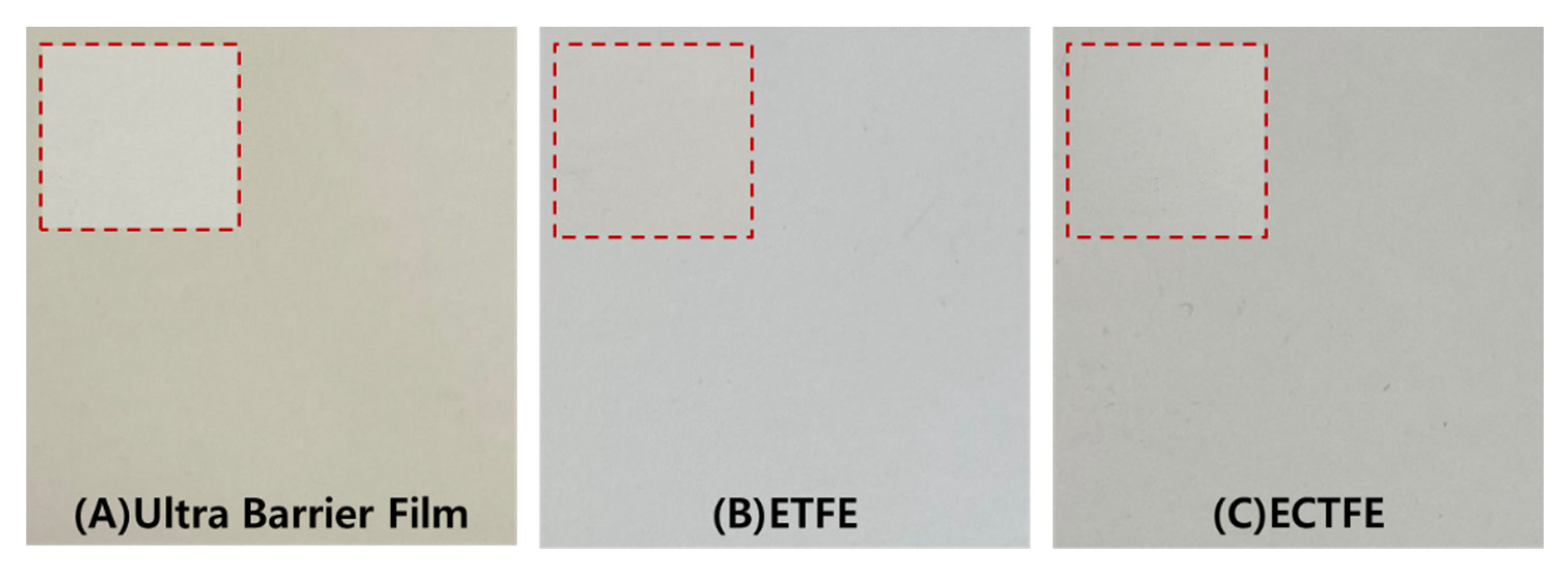
2.1. Analysis of Transmittance Characteristic of Front Materials

In general, PV modules use low-iron tempered glass as a front-surface material. The low-iron tempered glass protects the solar cell from the external environment, and the iron content is as low as 0.02% so that many photons can reach solar cells. In addition, when anti-reflective coating is applied to the entire glass surface to reduce reflection of the PV module, the transmittance is 90% or more and the reflectance is 5% or less. For this reason, the low-iron tempered glass PV module can achieve excellent electrical output and reliability. In order to apply this type of front-surface material in the PV module, the electrical output of the low-iron tempered glass PV module and the output after the reliability characteristics should be similar. In terms of the manufactured PV module with a front-surface film, this must pass reliability tests in accordance with the IEC (International Electrotechnical Commission) 61215 certification standards [16]. In particular, the transmittance of the PV module front-surface materials is an important factor because it affects the short circuit current generated by the c-Si solar cell. When the transmittance of the material on the front surface of the PV module is low, the short circuit current is lowered, resulting in a lower electrical output and efficiency of the PV module. Therefore, in order to apply a new front-surface material to a PV module, it is first necessary to analyze the transmittance.
Table 1 shows the characteristics of the ultra-barrier film and ETFE and ECTFE films used in the experiment. The transmittance was measured 10 times for each sample using a V-670 UV-spectrometer to confirm the reproducibility of the experiment. The reproducibility of measurements was very good at less than 0.2%.
The experimental results show that the average transmittance of ECTFE film was the best, and the transmittance was higher in the PV modules with the ultra-barrier and ECTFE films than with the ETFE film. However, it can be seen that the difference in transmittance was about 0.2%, indicating the transmittance was highly similar. From the results of measuring the transmittance and weight, it is believed that the front-surface film can be applied to the solar module. In order to apply the films to the front surface of the PV module, the UV reliability characteristics of each were analyzed.

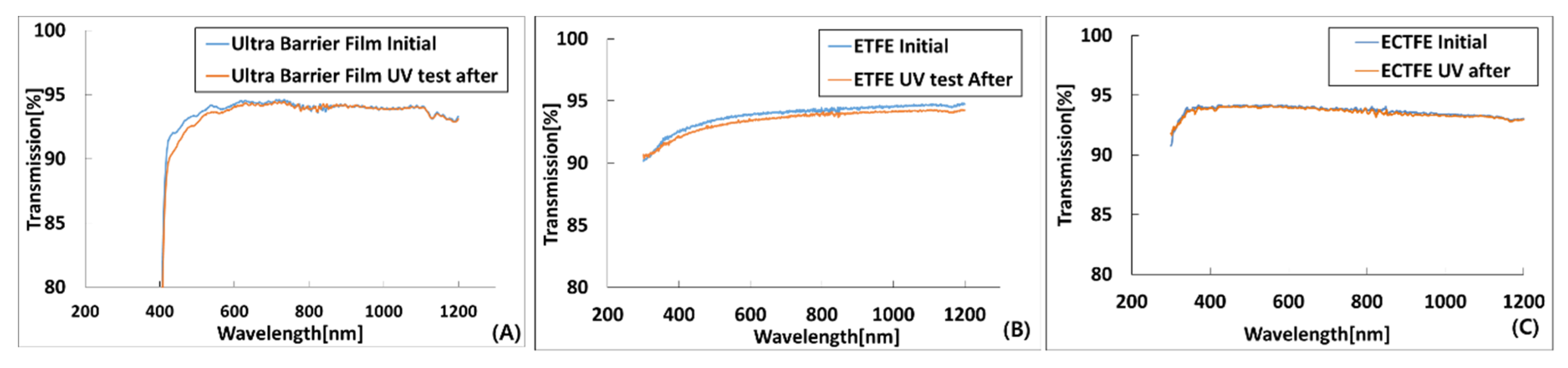
2.2. UV Characteristic Analysis of Front-Surface Materials of PV Module

The change in the transmittance of the front-surface material can alter the reliability characteristics as well as the electrical output of the PV module. In addition, since the front-surface material of the PV module is exposed to the harsh outdoor environment and is directly exposed to sunlight, there is a high possibility of UV altering the properties. Because solar modules are guaranteed for a period of more than 20 years, the discoloration of the front-surface material of the PV module by UV is an important factor to consider. A photovoltaic module that generates electricity in the field is continuously exposed to UV from sunlight. If it is exposed for a long period of time, it is necessary to analyze the front-surface materials of the PV module because severe discoloration and power deterioration will occur. Therefore, UV tests as well as transmittance are essential for the front-surface material of a PV module. In this paper, the transmittance was measured before and after the UV test to analyze the UV characteristics of films that are suitable as the front material. The UV test was conducted under conditions of 15 kWh/m2 irradiance from 280 to 385 nm based, and module temperature at 60 °C ± 5 °C on IEC 61215, and then the transmittance of the front materials was measured. Figure 1 shows each sample after the UV test.
After the UV test, a slight discoloration of the polymer protective film could be observed with the naked eye, but the ETFE and ECTFE films hardly changed. This was confirmed from the change in transmittance in Figure 2; in the case of UBF, the transmittance decreased by about 0.2% in the 400~120 nm range. However, the ETFE and ECTFE films showed little change in transmittance. In other words, it was confirmed that ETFE and ECTFE films have superior UV characteristics compared to those of UBF.

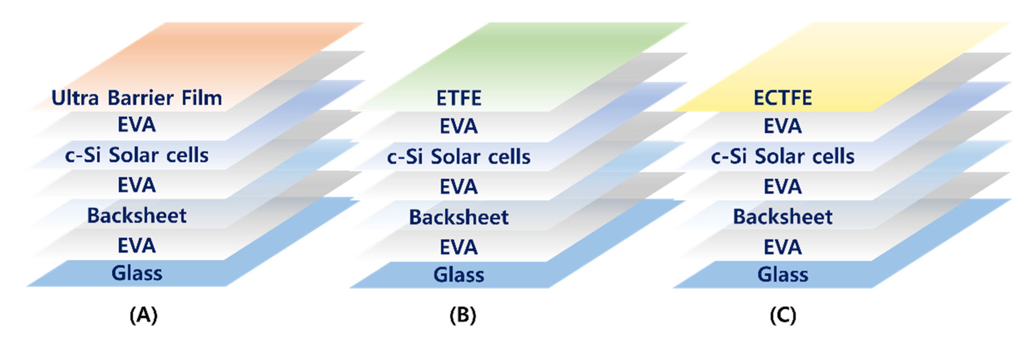
3. Experiment on the Electrical Output and Reliability Characteristics of Front Materials of PV Module

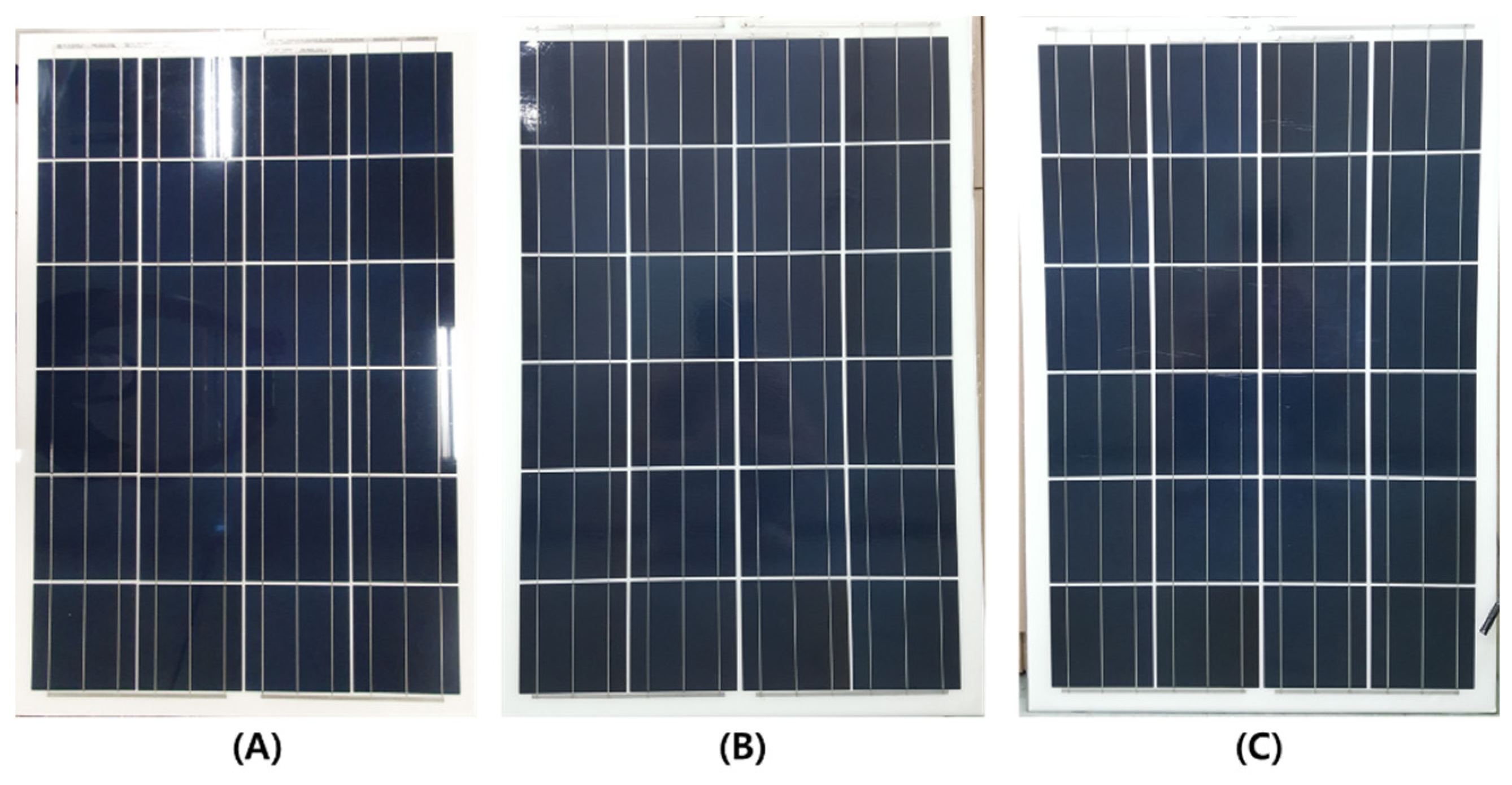
3.1. Analysis on the Electrical Output of PV Module

In the previous chapter, we compared and analyzed the front-surface material properties of the PV module. As a result of the experiment, it was confirmed that the film used in the experiment was lightweight and had excellent transmittance and UV characteristics. In this chapter, a PV cell module was fabricated using the previously analyzed film, and electrical output and reliability tests were conducted. The solar cell used in the experiment is a multi-crystalline c-Si solar cell, and a PV module was manufactured after sorting the solar cell to make the experiment accurate. Solar cells with an output deviation of less than 1% were used, and the solar simulator for measuring the electrical output was tested at optical class AAA and temperature at 25 °C. PV modules with films applied to the front have the same structure as conventional modules, with the only difference being that film is used instead of low-iron, tempered glass. In addition, the lamination process for manufacturing the solar module is the same, but a rear-reinforcing agent was added to prevent sagging at the rear. Figure 3 shows the lay-up structure of the front-film PV module.
Figure 4 shows the actual manufactured front-film, one-cell-sized solar module. In the case of a short circuit current, an output error may occur depending on the size of the front margin, so for accurate testing, black masking tape was applied to the margin of the back sheet, as shown in Figure 3. This is because if the size of the back sheet margin of each manufactured PV module is different, the amount of light reflected by the back sheet and incident on the solar cell varies, so accurate experimentation is impossible. Figure 4 shows the photovoltaic module with the film applied to the actual fabricated front surface and Table 2 details the electrical output. The c-Si solar cell area is 156.75 mm2.
By measuring the electrical output of the one-cell PV module, it was found that the short circuit current of the PV module using UBF as the front material was 8.4 A. In addition, ETFE and ECTFE PV modules have a short circuit current of 8.5 A, which is similar to that of UBF PV modules. All open-circuit voltages were 0.62 V, and also fill factor (FF) also did not show a significant difference. The difference in output of the photovoltaic modules with the film applied to the front was approximately 0.05 W, so there was no significance.

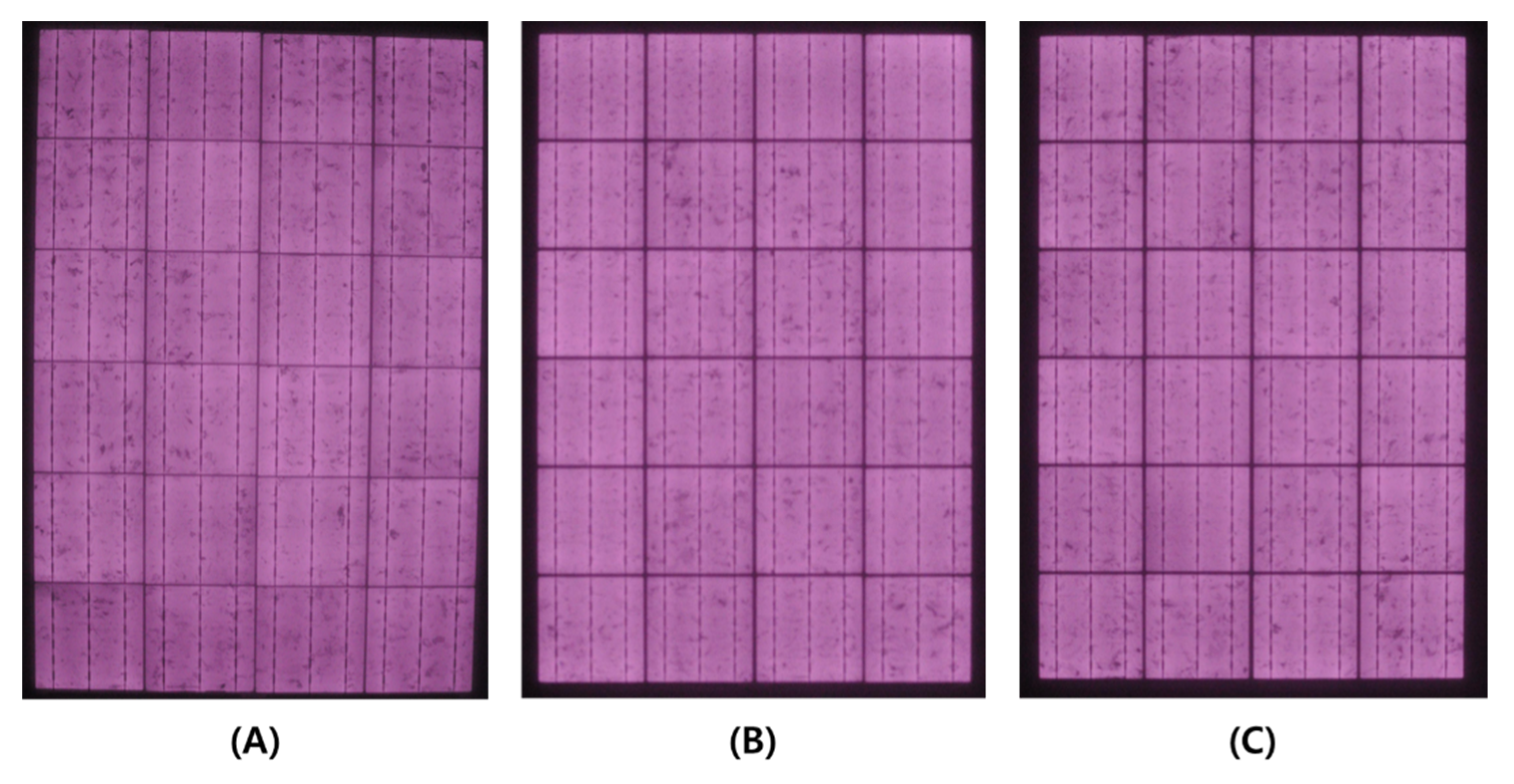
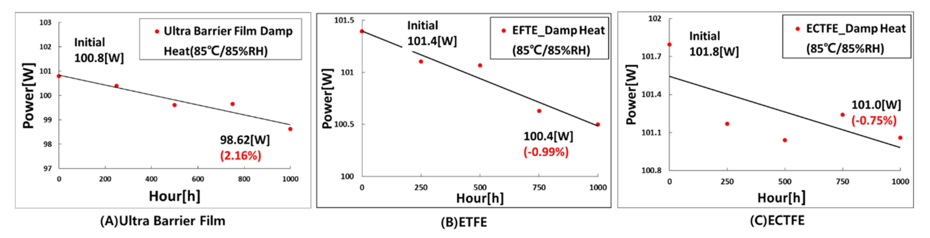
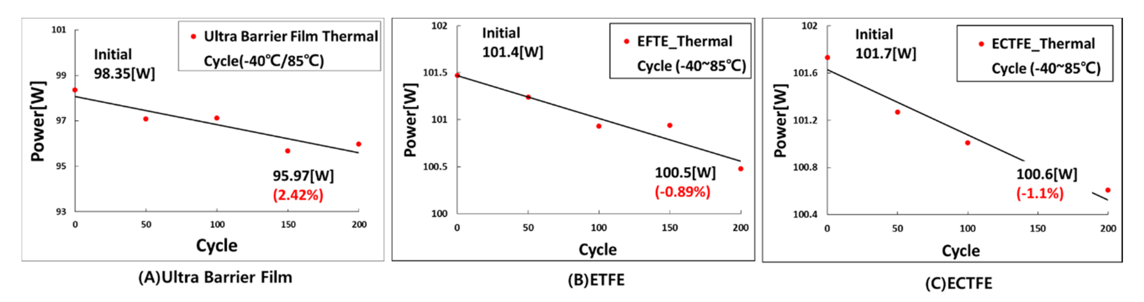
3.2. Reliability Analysis of ETFE, ECTFE and Ultra-Barrier Film PV Module

PV modules installed in PV power plants are manufactured by connecting 60 or 72 solar cells in series to increase the voltage, as individual solar cells have a low voltage. In other words, the photovoltaic module used in the actual photovoltaic power plant is not a one-cell-sized module, so the reliability and electrical output were evaluated in this paper by fabricating a lab-scale 24-cell module. In the case of a PV module using a film on the front surface, there is a possibility of sagging.
In the case of sagging in a PV module, the crack phenomenon of the c-Si solar cell occurs. As a result, the electrical output cannot be accurately measured and the reliability characteristics cannot be compared and analyzed. In this paper, for accurate reliability analysis of the PV module with a film applied to the front, a PV module was fabricated by attaching reinforcing material at the rear side to prevent sagging.
The solar cell used in the experiment was a multi-crystalline solar cell, which is the same as the one-cell-sized PV module, and the PV module was manufactured after performing the sorting process in the same manner as in the previous experiment. The lab-scale photovoltaic module was also laid-up in the same structure as the one-cell PV module, and then the module was manufactured via the lamination process. Figure 5 shows the 24-cell PV modules to which the manufactured front-surface film was applied.
In Table 3, the output measurement of the short circuit current of the ECTFE film with the best transmittance was slightly higher, but the overall current value was similar. In addition, the open circuit voltage and fill factor (FF) had the same values. The Pmax (maximum power point) was approximately 1 W higher in the PV module using ECTFE than in the ultra-barrier film PV module, which is due to the difference in the light transmission of the different photovoltaic modules. However, this results equates to less than 1% of the output, so there was no significant difference.
When using a film or plastic material on the front surface of the PV module, the mechanical strength of the module is not secured. Therefore, the use of film-based materials on the front surface is widely used in flexible solar cell or amorphous solar cell modules. If the film is applied to the front of the c-Si PV module, the solar cell may be damaged. Therefore, it is necessary to check whether the PV module is cracked using EL (electroluminescence). In this paper, EL was measured after module fabrication, and Figure 6 shows the measured EL image. The results of the measurement show that no crack phenomenon occurred in the PV module when using the film on the front surface.
Because PV systems generate power in harsh outdoor environments, the reliability of PV modules is a critical factor. Here, the reliability of the PV module refers to tests such as the damp heat and thermal cycle based on the certification test. A reliability test refers to the stable function of the product by properly maintaining the PV module in the harsh external environment. Recently, PV modules have been designed using various types of front-surface materials, but most of the general mass-produced modules are still manufactured using glass. However, changing the front-surface material of the module may result in adhesion problems between the material and EVA, which can lead to a decrease in the reliability of the PV module. In this chapter, a reliability test was conducted for the final evaluation of the PV module to which the film was applied.
Damp heat and thermal cycle tests were conducted for the PV module, and a reliability evaluation was performed using the test method based on IEC 61215. The damp heat test is a test that evaluates the decrease in output due to the stress generated at the junction of the solar cell and the ribbon under high-temperature and high-humidity conditions. It was tested for 1000 h at a temperature of 85 ± 2 °C and humidity of 85 ± 5%RH(relative humidity). The thermal cycle test assesses the thermal stress and durability of the module as a function of the change in outdoor temperature, and is tested 200 times in the temperature range of −40 °C~85 °C, corresponding to 1 cycle.
From the results of the reliability test in Figure 7 and Figure 8, it was shown that all of the PV modules with a film applied to the front surface had excellent reliability characteristics. The criterion for the IEC 61215 reliability test of a solar module is failure when the output decreases by more than 5% compared to the initial value after the reliability test. The c-Si PV module with a film applied to the front showed excellent properties, with 0.75% to 2.42%—less than the 5% failure criterion. In other words, the reliability of the solar module with the film applied to the front surface was confirmed.

4. Conclusions

In this paper, the transmittance and UV characteristics of film materials were analyzed to examine the applicability of the front-surface film to the PV module. In addition, the films were applied and manufactured as a PV module, and the reliability and electrical output were analyzed.
First, from the analysis of the properties of the front-surface film, the average transmittance was found to be excellent, at 93.3–93.7%. The change in transmittance before and after the UV test was insignificant, at less than 2%. In addition, the electrical output was analyzed by fabricating one-cell and 24-cell modules by applying a film to the front surface. For the short circuit current and output, the ETFE and the ECTFE films had slightly higher values than those of the UBF film, but the difference in values between films was only 1%, confirming that the same output level can be secured regardless of the film material used. Finally, damp heat and thermal cycle tests were performed to evaluate the reliability of the PV module with the film applied to the front surface. After the damp heat test of the front-surface film photovoltaic module, the decrease in output was 0.75%–2.16%, and after the thermal cycle test, the output dropped by 0.89%–2.42%, confirming the excellent reliability characteristics of the manufactured PV modules.
The conclusions of this paper can be summarized as follows.
(1)
In order to apply the film as the front-surface material of the PV module, the material characteristics were analyzed, and one-cell and 24-cell modules were manufactured and tested for their electrical output and reliability.
(2)
The difference in electrical output of the PV modules to which the front-surface film was applied was equal to 1W or less.
(3)
As a result of damp heat and thermal cycle reliability tests, the reduction in the electrical output modules with front-surface films was within 5%, which is the certification standard.
(4)
If the mechanical strength is increased by using a reinforcing material on the back side, it is believed that these films can be used as the front-surface material of the PV module.
In this paper, the material properties of the film were investigated and the electrical output and reliability tests of the PV modules fabricated with the films were conducted. In the future, the results of this study could be utilized in the development of new types of PV modules, in particular, lightweight PV modules.

Author Contributions

J.R.L. wrote the main part of the paper, in particular, the results of the experiment. W.G.S. and C.G.L. established the research direction of the paper and suggested a method for conducting the experiment. Y.G.L. and S.W.K. analyzed the data using the paper and provided important comments. Y.C.J.; J.D.K. and G.H.K. provided technical ideas and assistance in establishing the experiment. H.H. reviewed and revised the overall contents of the paper. All authors have read and agreed to the published version of the manuscript.

Funding

This research received no external funding.

Acknowledgments

This work was supported by a the New & Renewable Energy Technology Development Program of the Korea Institute of Energy Technology Evaluation and Planning (KETEP) grant, funded by the Ministry of Trade, Industry and Energy, Korea (No. 20183010013960).

Conflicts of Interest

The authors declare no conflict of interest.

References

  1. Ha, S.W.; Park, S.H.; Eom, J.Y.; Oh, M.S.; Cho, G.Y.; Kim, E.J. Parameter calibration for a TRNSYS BIPV model using in situ test data. Energies 2020, 13, 4935. [Google Scholar] [CrossRef]
  2. Shukla, A.K.; Sudhakar, K.; Baredar, P. Recent advancement in BIPV product technologies: A review. Energy Build. 2017, 140, 188–195. [Google Scholar] [CrossRef]
  3. Gagnon, P.; Margolis, R.; Melius, J.; Phillips, C.; Elmore, R. Rooftop Solar Photovoltaic Technical Potential in the United States. A Detailed Assessment (No. NREL/TP-6A20-65298); National Renewable Energy Lab. (NREL): Golden, CO, USA, 2016. [Google Scholar]
  4. Al-Janahi, S.A.; Ellabban, O.; Al-Ghamdi, S.G. A Novel BIPV reconfiguration algorithm for maximum power generation under partial shading. Energies 2020, 13, 4470. [Google Scholar] [CrossRef]
  5. Mittag, M.; Ebert, M.; Wilson, H.R.; Fellmeth, T. Mosaic Module concept for cost-efficient and aesthetic BIPV modules. In Proceedings of the 35th European PV Solar Energy Conference and Exhibition, Brussels, Belgium, 24–28 September 2018. [Google Scholar]
  6. Saretta, E.; Bonomo, P.; Frontini, F. BIPV meets customizable glass: A dialogue between energy efficiency and aesthetics. In Proceedings of the 35th European Photovoltaic Solar Energy Conference and Exhibition, EUPVSEC, Brussels, Belgium, 24–28 September 2018; pp. 1472–1477. [Google Scholar]
  7. Tzikas, C.; Bognár, Á.; Loonen, R.C.; Hensen, J. Outdoor characterization of colored and textured prototype PV facade elements. In Proceedings of the 35th European Photovoltaic Solar Energy Conference and Exhibition, Brussels, Belgium, 24–28 September 2018; pp. 1468–1471. [Google Scholar]
  8. Halbe, A.; Novak, J.; Sharpe, K.; Housser, G.; Haldars, P. Evaluation of mounting mechanisms for the installation of lightweight PV systems on commercial rooftops. In Proceedings of the 2014 IEEE 40th Photovoltaic Specialist Conference (PVSC), Denver, CO, USA, 8–13 June 2014; pp. 3539–3542. [Google Scholar]
  9. Honeker, C.; Fuller, E.; Watts, A.; Booth, D.; Flaherty, B.; Mao, E. Reducing installed costs of residential solar by the use of adhesive mounted lightweight solar modules. In Proceedings of the 2016 IEEE 43rd Photovoltaic Specialists Conference (PVSC), Portland, OR, USA, 5–10 June 2016; pp. 3135–3140. [Google Scholar]
  10. Metacarpa, D.; Fobare, D.; Garney, A.; Yan, F.; Dwyer, D.; Holton, E.; Haldar, P. Reduced Balance of System Costs using Lightweight photovoltaics integrated with roofing material membranes. In Proceedings of the 2015 IEEE 42nd Photovoltaic Specialist Conference (PVSC), New Orleans, LA, USA, 14–19 June 2015; pp. 1–4. [Google Scholar]
  11. Agathokleous, R.; Kalogirou, S.A. Thermal testing of new photovoltaic (PV) modules for building integration, encapsulated with glass fibre reinforced composite materials and comparison with conventional Photovoltaic. In Proceedings of the First International Conference on Building Integrated Renewable Energy Systems, Dublin, Ireland, 6–9 March 2017. [Google Scholar]
  12. Martins, A.C.; Chapuis, V.; Virtuani, A.; Perret-Aebi, L.E.; Ballif, C. Hail resistance of composite-based glass-free lightweight modules for building integrated photovoltaics applications. In Proceedings of the 33rd European Photovoltaic Solar Energy Conference and Exhibition, No. CONF, Amsterdam, The Netherlands, 25–27 September 2017; pp. 2604–2608. [Google Scholar]
  13. Martins, A.C.; Chapuis, V.; Virtuani, A.; Ballif, C. Robust glass-free lightweight photovoltaic modules with improved resistance to mechanical loads and impact. IEEE J. Photovolt. 2018, 9, 245–251. [Google Scholar] [CrossRef]
  14. Martins, A.C.; Chapuis, V.; Virtuani, A.; Li, H.Y.; Perret-Aebi, L.E.; Ballif, C. Thermo-mechanical stability of lightweight glass-free photovoltaic modules based on a composite substrate. Sol. Energy Mater. Sol. Cells 2018, 187, 82–90. [Google Scholar] [CrossRef]
  15. Brounne, M.; Heuseveldt, J.W.; Rosca, V.; Okel, L.A.G. Novel light-weight PV module design based on use of polycarbonate. In Proceedings of the 35th European Photovoltaic Solar Energy Conference and Exhibition, EUPVSEC, Brussels, Belgium, 24–28 September 2018; pp. 1–16. [Google Scholar]
  16. Raut, H.K.; Dinachali, S.S.; He, A.Y.; Ganesh, V.A.; Saifullah, M.S.; Law, J.; Ramakrishna, S. Robust and durable polyhedral oligomeric silsesquioxane-based anti-reflective nanostructures with broadband quasi-omnidirectional properties. Energy Environ. Sci. 2013, 6, 1929–1937. [Google Scholar] [CrossRef]
  17. Webstore (International Electrotechnical Commission). Available online: https://webstore.iec.ch/search form&q=IEC%2061215 (accessed on 10 December 2020).
Figure 1. Front material after UV test (size: 4 cm2) (A) Ultra-barrier film (B) ETFE and (C) ECTFE (dotted line is the sample before UV test).
Energies 14 00163 g001
Figure 2. Transmittance of (A) ultra-barrier film, ETFE, ECTF before and after the UV test (B) Transmittance of ETFE (C) before and after the UV test.
Energies 14 00163 g002
Figure 3. Structure of PV module according to front materials (A) UBF PV module; (B) ETFE PV module; (C) ECTFE PV module.
Energies 14 00163 g003
Figure 4. Actually, manufactured one-cell photo-voltaic (PV) module (A) Ultra-barrier film, (B) ETFE, (C) ECTFE.
Energies 14 00163 g004
Figure 5. Actually manufactured 24-cell PV module (A) Ultra-barrier film, (B) ETFE, (C) ECTFE.
Energies 14 00163 g005
Figure 6. Electroluminescence (EL) image of PV module; (A) UBF 24-cell (B) ETFE 24-cell PV module; (C) ECTFE 24-cell PV module.
Energies 14 00163 g006
Figure 7. The result of the damp heat test of the PV module with the film applied to the front surface (A) Ultra-barrier film (B) ETFE and (C) ECTFE.
Energies 14 00163 g007
Figure 8. The result of the thermal cycle test of the PV module with the film applied to the front surface (A) Ultra-barrier film (B) ETFE and (C) ECTFE.
Energies 14 00163 g008
Table 1. Characteristics of front-surface materials.
Weight   [ g / c m 2 ] Product Thickness [mm]Transmittance Average [%]Maximum Transmittance
ARC (anti reflective coating) Glass0.8753.295.07 [17]95.2 [17]
Ultra barrier film0.0270.293.594.6
Ethylene tetra fluoro-ethylene (ETFE)0.0090.293.394.8
Ethylene chlorotrifluoroethylene (ECTFE)0.0060.0593.794.2
Table 2. Electrical output of one-cell PV module for each of the different front-surface materials.
V o c   [ V ] I s c   [ A ] P m a x   [ W ] FF [%] R s   [ Ω ]
Ultra-barrier film0.628.43.9575.10.01
ETFE0.628.54.0174.90.01
ECTFE0.628.54.0074.00.01
Table 3. Electrical output of 24-cell PV module for the different front-surface materials used.
V o c   [ V ] I s c   [ A ] P m a x   [ W ] FF [%]
Ultra-barrier film15.38.89100.874.4
ETFE15.38.94101.574.2
ECTFE15.38.97101.874.2
Publisher’s Note: MDPI stays neutral with regard to jurisdictional claims in published maps and institutional affiliations.

