1. Introduction
Electric vehicles (EVs), including railway, public service, and personal vehicles, play an important role in building a clean and efficient environment in the transportation market [
1,
2,
3,
4,
5]. They reduces the pollution, gas emissions, and the reliability of fuel oil. With the permeation of EVs in recent decades, they are considered a new major load in the main grid and distributed systems [
6]. When connected to the grid, EV batteries can deliver power to the grid as energy storage devices. When the EVs consume power, it is denoted as a grid-to-vehicle (G2V) operation. On the other hand, it is known as a vehicle-to-grid (V2G) operation when the energy is provided from the EVs to the grid [
7,
8]. Therefore, the installation of bidirectional EV charging stations is needed to fulfill the demands mentioned above.
As a new paradigm of transport devices, EV batteries have the ability to compensate the grid with active power via the bidirectional chargers. The current chargers can be classified into several types in terms of the location (on-/off-board) and function (unidirectional/bidirectional) [
9]. In a recent work, Kwon et al. proposed an electrolytic capacitor bidirectional EV charger to exchange the active power between the grid, EVs, and smart homes [
10]. In [
11], Zahid designed a bidirectional DC/DC resonant converter to reduce the cost and size of the chargers for V2G operation. As control methods for converters have developed in recent years, it is now possible for the EVs to exchange the reactive power with the main grid, in addition to the active power. A system in which EVs can participate in the microgrids as the reactive power provider was presented in [
12]. The economic efficiency from different aspects, including the energy market, reactive market, and lost opportunities, was analyzed to show the effectiveness of EV participation. The reactive power compensation capabilities of EVs in two different bidirectional battery converter topologies were investigated in [
13]. EV batteries were used as static var compensators to support the main grid; this was named the vehicle-for-grid (V4G) mode in this paper. Under this working condition, the reactive power is transmitted between the EVs and the power grid. In [
14], the EV batteries could operate only in the V2G mode or with reactive power operation. It is impossible for the controller to meet the active and reactive power requirements at the same time. In [
15,
16], reactive power could be controlled to be provided from/to the EVs. According to the types of the operation modes, the current references of the EV and grid sides were generated and sent to be used according to the pulse width modulation (PWM) strategy. Then, the bidirectional chargers were able to operate in the V2G/G2V/V4G modes in smart grids or homes.
Compared with the PWM strategies for current-tracking targets used in [
14,
15,
16], an advanced model predictive control (MPC) algorithm was proposed with no need for modulation. Due to its easy implementation and its combination of multiple objectives, the MPC scheme has recently attracted researchers [
17,
18]. The adoption of the MPC method strongly depends on the calculation speed of the components and system. With the application of microprocessors, it is now possible to apply it in the MPC method to control powered electronic devices [
19]. A cost function was designed to select an optimal switching state for the next sampling period [
20]. The model predictive direct power control with duty cycle optimization was proposed to control the PWM rectifier [
21]. A nonzero vector and a zero vector operating with optimal control times were selected to achieve better system performance. In [
22], the model predictive current control was applied on the grid side to track the grid current reference. Currently, the predictive control strategy is used for unidirectional power flow in general. The active power is delivered from the grid side to the load side.
To achieve bidirectional active/reactive power flow (four-quadrant operation), a cascaded model predictive control is proposed in this paper. The controller is divided into two parts. One is for the active and reactive power control used in the grid side, denoted as the model predictive direct power control (MPDPC). The combination of the active and reactive powers’ errors is designed as the cost function. It is used to track the active/reactive power demands for the power grid. Another is the current control for the EV side to achieve a constant current charging target, which is named the model predictive direct current control (MPDCC). The key novelties of the paper can be summarized as follows: (1) The active and reactive powers can be controlled independently with the cascaded predictive control; (2) EV batteries regarded as the reactive power generator (V4G mode) are proposed to support the main grid; (3) the initial constant current control for charging/discharging operation is available on the load side.
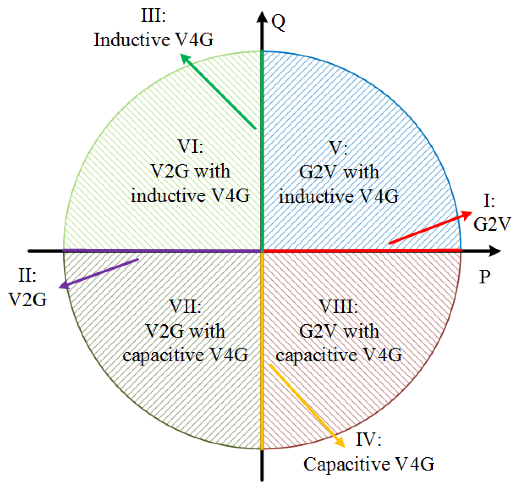
In this paper, a three-phase laboratory converter and a DC/DC half-bridge converter were developed as the bidirectional EV charger. Simulation and experimental tests were implemented to verify the proposed method in the four-quadrant operation. The detailed working scenarios were: (1) the pure G2V operation mode; (2) the pure V2G operation mode; (3) the pure inductive V4G operation mode; (4) the pure capacitive V4G operation mode; (5) the G2V along with the inductive V4G operation mode; (6) the V2G along with the inductive V4G operation mode; (7) the V2G along with the capacitive V4G operation mode; (8) the G2V along with the capacitive V4G operation mode. It should be noted that the inductive/capacitive operation refers to positive/negative reactive power during the transmission.
The rest of this paper is presented as follows.
Section 2 discusses the topologies, application fields, and pros and cons of the unidirectional and bidirectional chargers. In
Section 3, the selected off-board EV battery charger prototype is introduced and the proposed MPC methods for both the first stage and second stage are explained in detail.
Section 4 and
Section 5 present the simulation and experimental results of the bidirectional charger under the G2V, V2G, and V4G operation modes. Finally, the conclusions are shown in
Section 6.
3. Proposed System and Control Scheme for Bidirectional Power Flow
With the integration of EVs, car parks located in workplaces or shopping malls show enormous potential for getting EVs involved in the grid. To exploit this commercial potential, a smart car park where large populations of EVs would be parked was proposed in a previous work [
26]. The proposed smart car park system consists of bidirectional charging stations, a control center, and energy storage devices, as presented in
Figure 3. The active/reactive power management system can be regarded as a central controller. The power demands from the EVs and storage system (such as a supercapacitor/flywheel) are sent to this central controller. Optimal control strategies are applied to generate the control signals. The switching states are transferred to drive the relevant converters or devices.
The bidirectional chargers should be controlled to track the active/reactive power and charging/discharging current references provided from the grid and EVs, respectively. Due to the easy implementation and ability to fulfill multiple objectives, the proposed MPC method is designed to track these targets. The classical topology in
Figure 2b is used for energy storage systems with the bidirectional power flow [
27]. However, as a boost converter, the range of the battery voltage is limited, varying from the grid peak voltage to the battery maximum voltage [
28], which will be proved later in this section.
Considering that the common nominal battery voltage is between 300 and 400 V, an AC/DC boost converter, the typical topology, is preferred in the rectification stage with a 120/240 V grid connection [
25]. A DC/DC half-bridge bidirectional converter is used to interface with the EV batteries. With this DC/DC converter, the low boundary of the charging/discharging range can be enlarged from the peak value of the grid voltage to 0 V.
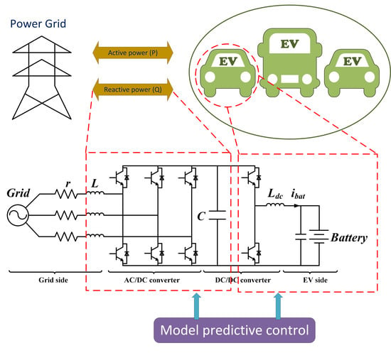
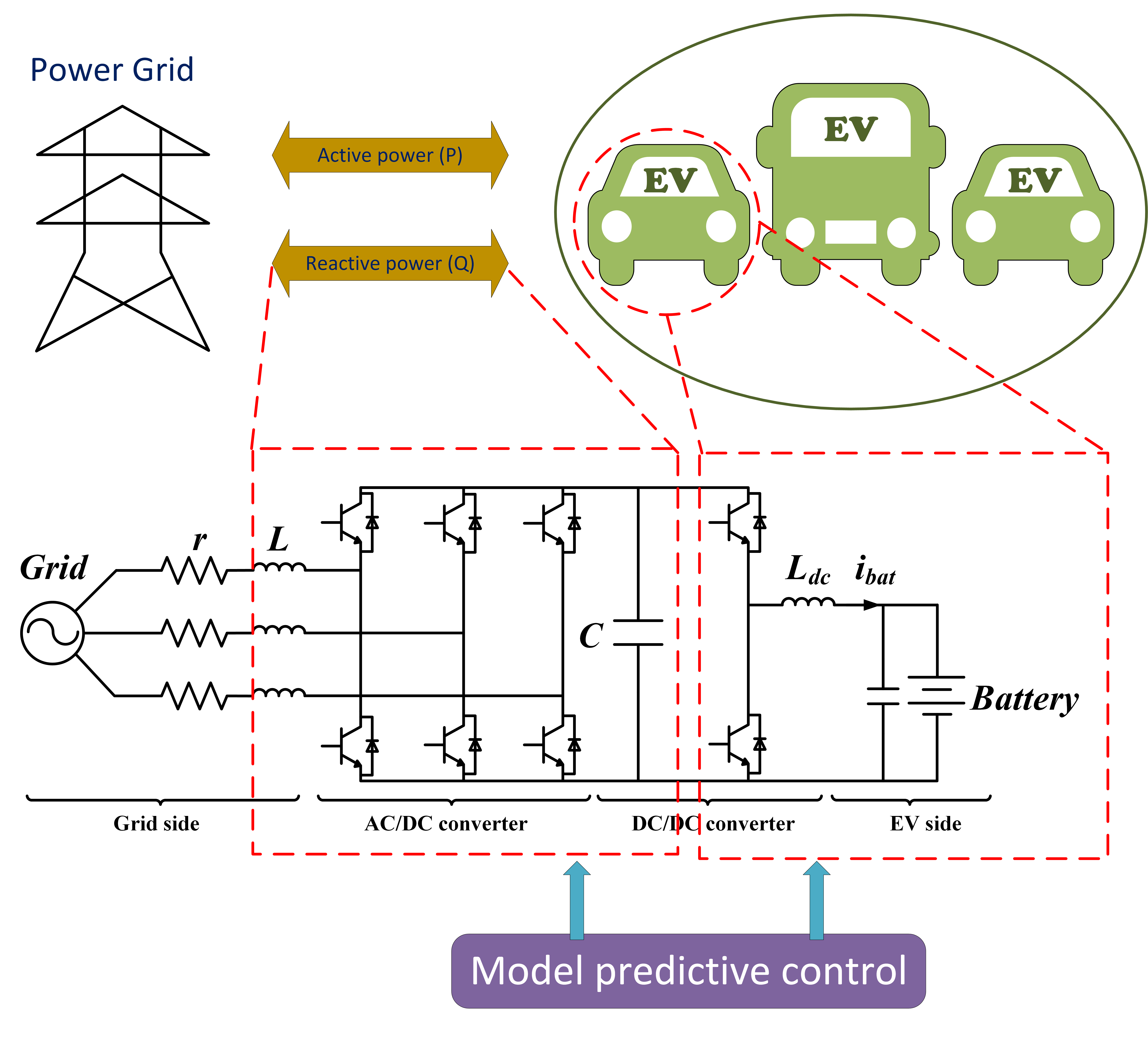
Based on the above analysis, a three-phase two-stage converter is used as the off-board bidirectional charger, as depicted in
Figure 4. The two-level AC/DC converter is connected with the power grid via a line resistance (
R) and a filter inductor (
L). A filter capacitor (
C) is connected on the DC bus to smooth the DC voltage. The half-bridge DC/DC converter is applied as the second stage. An output inductor (
) connecting the battery is used on the DC side.
The switching signals of the three-phase AC/DC converter are defined as
where
k =
a,
b,
c phase.
The switching state is transformed into the stationary
coordinate system, written as
where
Similarly, the input voltage of the AC/DC converter in the
coordinates can be expressed as:
The eight possible switching states and the corresponding input voltage vectors are summarized in
Table 1.
3.1. The Charging Rate Analysis
Assuming that the reference voltage
is located in sector 1 of the vector diagram presented in
Figure 5, based on the parallelogram law, it can be obtained from the two closest voltage vectors (
and
), expressed as
where
,
, and
are the action periods for the three basic voltage vectors,
,
, and
, respectively.
In the
coordinate system, the included angle between the reference value (
) and the voltage vector (
) is denoted as
. Based on the law of sines, the relationship among
,
, and
can be recorded as
Because
and
have the same amplitude, which is equal to
, (
4) and (
5) can be rewritten as
where
m is the modulation in index, which can be calculated by
In the space vector modulation, a system constraint condition should be met:
Substituting (
6)–(
8), the system constraint can be represented as
In order to satisfy (
9) for any included angle
, it can be deduced that
which can be rewritten as
where
is amplitude of the phase voltage and
is the phase-to-phase voltage, known as the line voltage.
Therefore, the output DC-link voltage
of the three-phase AC/DC converter has a minimum value. With the topology in
Figure 2b, the DC-side output voltage is limited to between the voltage-line voltage and the fully charged voltage of the battery. In order to achieve the full range of charging/discharging from the minimum to the maximum battery voltage, a DC/DC bidirectional half-bridge converter is connected with the battery, as described in
Figure 4.
3.2. Model Predictive Direct Power Control for the Grid Side
The MPC strategy for tracking the grid active/reactive power—named MPDPC—is proposed in this section. A cost function is designed as the combination of the error between the predicted and expected values of the active and reactive powers. The appropriate switching state that minimizes the cost function is chosen for the next sampling period.
A balanced source power is considered on the AC side. The system model in the standard
frame transformation can be written as
where
and
represent the grid voltage and phase current vectors, respectively, and are expressed by
Based on the forward Euler approximation, the derivative of the grid current can be assumed as
The grid current (
12) in the discrete time domain can be written as
Then, the active/reactive powers for the next time instant
are predicted as
where
,
,
, and
are the predicted values.
and
are obtained from (
14). Due to the large value of the rate between the grid frequency and sampling frequency,
and
can be assumed to be same as the measured values,
and
, respectively.
The cost function is designed as
The commands of the active/reactive powers ( and ) are determined by the center controller to satisfy the requirements of the grid and the EV customers.
3.3. Model Predictive Direct Current Control for the EV Side
For the half-bridge DC/DC converter, the switching state
G is defined as
This means that the switching state G is set to 1 when the upper switch is on and the lower one is off, or vice versa.
Based on Kirchhoff’s voltage law (KVL), when
G is controlled to be 1, the DC-link voltage can be obtained as
where
is the voltage on the DC bus,
is the battery voltage, and
is the battery charging/discharging current.
Similarly, when the switching state
G is 0, the KVL value of the DC/DC converter can be expressed as
Based on (
19) and (
20), the mathematical model of the bidirectional DC/DC converter can be written as
Then, the predicted battery current at the
time instant is obtained as
For constant current charging, the cost function
is defined as
where
is the reference value of the battery current.
Neglecting the power loss in the transmission, the grid active power reference (
) can be calculated as
where
,
and
are the charging power reference, voltage, and expected charging current of the
nth EV battery, respectively,
N is the total number of the parked EVs, and
is the power delivered to the storage system. In this paper, as an example,
N is set to 1 without the storage system, which leads to
. The proposed control algorithm is shown in
Figure 6.
4. Simulation Results
In [
14], Metin et al. used a proportional-integral controller (PI) controller for V2G reactive power operation with an off-board charger. With the proposed system controller, the reactive power reference can be tracked effectively while charging the EV battery. However, it took around three grid cycles (60 ms) to respond to a new command.
By using the proposed MPC method for the system in [
14] under the same transient simulation operation, the response time can be reduced dramatically. From the zoomed version of the active and reactive power in
Figure 7a, it can be seen that the response time for the system changing from a unity power factor operation to a 0.4 pf (leading) operation is less than 2 ms. Compared with the three-cycle (60 ms) response time in [
14,
15], the response speed is improved significantly. The grid current in
Figure 7b can also reach the new command operation within 2 ms.
This section provides the simulation results of the proposed control method for the four-quadrant P-Q operation in Matlab/Simulink. The parameters of the bidirectional charger were chosen as shown in
Table 2. The simulation scenarios are designed as follows:
- (1)
The charging current declines from 6.67 to −6.67 A at t = 1.04 s, which leads to the active power reference dropping from 2 to −2 kW. It steps up to 0 A at t = 1.08 s and stays constant for the next four cycles. Meanwhile, the reactive power reference stays at 0 kvar during the first four-cycle period. Then, it rises to 1 kvar at t = 1.08 s and drops to −1 kvar at t = 1.12 s.
- (2)
The charging current is decreased from 6.67 to 3.33 A at t = 1.04 s, which means that the active power reference is reduced from 2 to −1 kW, and after two cycles, it is restored to 6.67 A. At t = 1.12 s, it steps down to −3.33 A with equal to −1 kW. During this period, the reactive power reference is reduced from 1 to −1 kvar at t = 1.08 s.
Figure 8 presents the results of the first operation condition, which was used to describe the system performance in the independent operation of G2V, V2G, and (capacitive/inductive) V4G. The active/reactive power demands can be tracked effectively by using the proposed MPC strategy. In Modes I and II, no reactive power is transferred in this operation. Based on the active power reference, the bidirectional charger works effectively in the G2V and V2G modes. The grid current is controlled to be in phase with the grid voltage, as in the operation in the G2V mode. The EV batteries charge the energy from the source. The total harmonic distortion (THD) of the grid current is around 4.23%. Conversely, the active power is delivered from the EV to the grid in the V2G mode. It can be seen that the current is in phase opposition with the grid voltage. In Modes III and IV, the converter supports the grid with the reactive power compensation (V4G operation). With the reactive power being delivered from the grid to the load side, the grid current is
and leading the grid voltage; otherwise, it is
and lagging behind, as shown in
Figure 8c.
The second simulation was performed to show the system dynamic and steady-state performance in the four-quadrant regions of the PQ plane, as described in
Figure 9. The bidirectional charger works in G2V or V2G with the capacitive or inductive V4G operation modes. Similarly, it can be observed clearly in
Figure 9a that the system can track the references of the active and reactive powers at the same time.
Figure 9b,c shows the battery operation details and the grid-side performance in the a-phase, respectively. In Mode V, where the charger operates in G2V with inductive V4G operation, the main power grid provides the positive active/reactive power to the load. The grid current leads its voltage, as depicted in
Figure 9c. The system operates as V2G with the inductive V4G mode in Mode VI, delivering the active power from the EV battery to the power grid. The system serves as a static var generator to compensate the reactive power in V2G or G2V with capacitive V4G operation (Modes VII and VIII). The grid current lags behind the same-phase voltage in both operation modes. The battery is charged and discharged according to the transmission direction of the active power.
5. Experimental Results
The proposed control strategy was further verified by a scaled-down experiment that used a laboratory setup, as shown in
Figure 10. The setup was composed of the following devices: an insulated-gate bipolar transistor-based three-phase two-stage bidirectional converter, three AC filter inductors, and DC power sources. Twelve 12 V 24 Ah sealed lead-acid batteries connected in series were used to simulate an EV battery. Therefore, the nominal voltage and the capacity of this sealed battery were 144 V and 24 Ah, respectively. The experimental parameters are listed in
Table 3. The control algorithm was implemented on a dSPACE DS1104 processor board. The operations were performed with a sampling frequency equal to 10 kHz. All of the measured parameters were viewed through the dSPACE control desk. Note that during the experimental test, the battery contactor should be closed prior to turning on the main power on the AC side. Otherwise, a current spike occurs due to the voltage change between the DC bus (
) and the battery (
). Since there is a direct connection between the converter output capacitor and the battery, this current spike cannot be controlled. It might even destroy the converter output contactor and the battery contactors, as well as other semiconductor devices.
In the experimental test, the charging and discharging current references were set to be 2 and −2 A, respectively. The battery voltage was about 154 V. The active power demand delivered from the grid was around 308 and −308 W for the charging and discharging processes, separately. For inductive and capacitive operations, the reactive power references were 200 and −200 var, respectively.
Figure 11 shows that the system operates properly in Quadrants I, II, III, and IV. The battery can be charged and discharged with the proposed MPDPC and MPDCC strategies. The grid active and reactive power is well maintained according to the reference values presented in
Figure 11a. The battery current can track the reference value (2 and −2 A) effectively, as shown in
Figure 11b.
Figure 11c depicts the experimental current and voltage waveforms in the a-phase. The input current has a nearly sinusoidal waveform. When the reactive power is 0 var, it is in or out of phase with the grid voltage depending on the direction of the active power.
In
Figure 12, the reactive power is varied from 200 to −200 var, and the active power is controlled to change between 308 and −308 W. It can be seen clearly that during this process, not only can the active power be delivered between the EVs and the grid, but the reactive power can also be provided or absorbed by the EV battery.
Figure 12c presents the grid voltage and current waveforms. The response time is only approximately 2 ms for the system to reach the next demand condition.
6. Conclusions
This paper proposed a model predictive control composed of model predictive direct power control and a model predictive direct current control schemes for three-phase two-stage off-board bidirectional EV chargers. The MPDPC method was designed to track the grid active/reactive power references for the AC/DC converter. The MPDCC scheme was applied in a second-stage DC/DC converter for constant current charging. The proposed system controller receives the discharging and charging currents from the EV charging stations. With the proposed method, the bidirectional charger can operate in G2V or V2G with/without the capacitive/inductive V4G modes. The EV battery can not only exchange active power with the grid, but can also function as a static var compensator to improve the power quality based on the grid requirements. It can be seen from the simulation and experimental results that the designed MPC scheme has a fast dynamic response and good steady-state performance. The demands from both the grid and the EV batteries can be met effectively. However, there are some gaps between the laboratory and real-life off-board EV chargers, including the power level, charging conditions, and battery types. (a) In the real-life EV chargers, the power level is much higher than in the laboratory ones. In the US Society of Automotive Engineers (SAE) J1772 standard, DC Level 1 and DC Level 2 are the two levels of fast DC charging, with a rated power equal to 80 and 400 kW, respectively. (b) Only the initial constant current charging operation is considered in this paper. Generally, the constant voltage charging mode in the final process is required in most real cases. (3) In the current EV market, due to their long lifetime and high energy density, lithium batteries are used in the real vehicles, rather than sealed lead-acid batteries. (4) An isolated DC/DC converter is used in real-life chargers to protect EV batteries and the grid. To narrow the gap between the scaled-down laboratory setup and the real-life deployment, a high-power-level topology with an isolated DC/DC converter interfaced with lithium batteries will be considered in future work.


