1. Introduction
In recent years, the research on electrical machines has gradually become increasingly integrated, comprehensive, and synergistic, expanding from a single physical field to multiple physical fields, including electromagnetics, thermal, noise, and structure. For many lower speed applications, the main design limits are usually considered to be a combination of electromagnetic and thermal [
1]. Both these physical fields are deeply coupled with the characteristics interacting with each other. The losses generated by the electromechanical conversion process will raise the temperature. Consequently, the increase in temperature increases the resistance losses due to the positive temperature coefficient of resistivity. The steady-state temperature of the motor is the result of a balance between the generation and dissipation of heat, the cooling system being the decisive factor.
Each type of electrical machine has its own commonly used cooling system. Turbo-generators typically remove the heat that is mainly generated by the winding using forced air convection [
2]. In this study, forced cooling air flows through the air gap and radial ventilation ducts, removing heat from the convective surfaces. For the “slender” shape form typical in turbo-generators, the limited cooling capacity of forced air leads to a phenomenon that the temperature of the components near the fan is slightly higher than the inlet air temperature, but the temperature rises significantly at locations which are axially further away. This can result in excessive local temperatures with exponentially reduced insulation service life. In general, the stator has a more pronounced effect on thermal performance than the rotor due to the heat source arrangement. Therefore, it is necessary to plan an effective cooling path by optimizing the geometry of the cooling system to reduce the maximum temperature and narrow the temperature gradient.
To ensure that an optimal design is achieved, the temperature distribution of the stator should first be accurately calculated. The common calculation approaches are divided into two categories: analytical and numerical. The analytical approach has the advantage of being very fast to calculate; however, the developer of the network model must invest significant effort in defining a circuit that accurately models the main heat-transfer paths [
3,
4,
5]. The combination of Electromagnetic Finite Element Method (EM FEM) and Computational Fluid Dynamics (CFD) provides an effective and high-fidelity approach in addressing electromagnetic-thermal coupled problem calculation [
3,
6]. EM FEM can accurately calculate the losses of each part of the stator under various operating conditions, while CFD is an approach that can deal with turbulence, convective and conductive heat transfer simultaneously [
7]. However, this numerical approach, while accurate, increases the complexity of the calculations.
Considering the physical size and geometrical complexity of the MW-class stator, numerical calculations of the full-scale coupled models are often time-consuming [
8]. The general solution of this problem is to simplify the model based on its axial and/or circumferential symmetry. However, for turboalternators with large length-to-diameter ratios, the axially symmetric decomposition fails to effectively reduce the computational complexity of the model. Accordingly, this paper proposes a single ventilation duct subsystem (SVDS) that is composed of one radial ventilation duct and its two sides of iron core and winding.
In the SVDS, the heat of the stator is mainly generated from the copper losses of the winding and iron core losses. The heat generated by the winding is transferred through the insulation from the inner to the outer surface. The heat of the winding part that is exposed to the radial ventilation duct is directly removed by the cooling air. The other part of the winding that is placed in the stator slot transfers its heat to the iron core. In the end, the cooling air within the radial ventilation duct takes the heat away from the convective surface of the iron core.
Due to the convective behaviour being strongly geometry dependent, the width of the radial ventilation duct can control the flow rate of cooling air flowing into the SVDS from the air gap. Meanwhile, the flow rate of the air gap is a function of the axial positions and the widths of the radial ventilation duct. The geometry of the winding and iron core determines the amount of heat generated, while the size of the radial ventilation ducts strongly impacts the fluid behaviour of cooling air and in turn also the cooling capacity. Therefore, according to the axial distribution of cooling air and the influence of each SVDS shunt, this paper proposes an innovative approach in the geometric design of non-uniform radial ventilation ducts. This approach not only improves the utilisation of cooling air but also reduces the calculation size and time required for a numerical calculation of the stator temperature.
The final step of the design is the determination of the geometric dimensions of the SVDSs. This process can employ a global optimization algorithm, such as the genetic algorithm (GA), to find the optimal design scheme in the feasible range of design parameters. However, the optimization based on numerical calculation is still expensive in terms of elapsed time and/or computational cost, so that only a limited number of simulations are possible. To that end, in this paper, a surrogate model is applied to reduce the time spent on each iteration within the optimization process.
The surrogate model inherently captures the underlying mapping among predefined input-output pairs by a way of data-driven. Data-driven methods, which are free of setting any mechanism a priori, are gaining increasing adoption in the field of performance prediction [
9,
10,
11] and parameter fitting [
12,
13,
14]. In electrical machine design, Kriging [
12], response surface [
13,
14] and multilayer perceptron neural network [
15] have been successfully applied to surrogate models for performance optimization, especially for solving the highly nonlinear problem of multi-physics coupled electrical machines. Compared with these methods, radial basis function neural network (RBFNN) has simpler structure and much faster training process, which is beneficial for the reduction of computational cost. Moreover, RBFNNs are better adapted to the environment and have been shown to approximate any continuous nonlinear network with arbitrary accuracy [
16]. Therefore, the RNFBB can reflect the corresponding model based on the actual sampling, that is, different numbers of samples will reflect different levels of accuracy of the model. This facilitates a balanced number of samples versus fidelity for the model.
From the foregoing discussion, the design of non-uniform radial ventilation ducts for the stator can be achieved. The contributions of this work can be summarized as:
The design methodology of the non-uniform radial ventilation ducts of the stator is presented. Through the optimization of the geometries and axial positions of the stator radial ventilation ducts, a reasonable distribution of the cooling air can be achieved. This not only reduces the maximum temperature of the stator but also narrows the temperature difference.
The construction of single ventilation duct subsystems. This simplifies the geometric complexity of the model and avoids the heavy computational cost of full-scale coupled numerical calculation.
The application of RBFNN surrogate model provides a solution to reduce the computational sophistication of the optimization objective function. Meanwhile, the isometric sampling method is proposed to balance the relationship between the number of sampling points and the distance between sampling points.
This paper is organized as follows.
Section 2 details the process of establishing the SVDS.
Section 3 describes the RBFNN surrogate model. The application of GA optimization methods is included in
Section 4. Finally, taking an existing turboalternator as a case study, the experimental validation together with the optimization results are presented in
Section 5 and
Section 6, respectively.
2. Single Ventilation Duct Subsystem
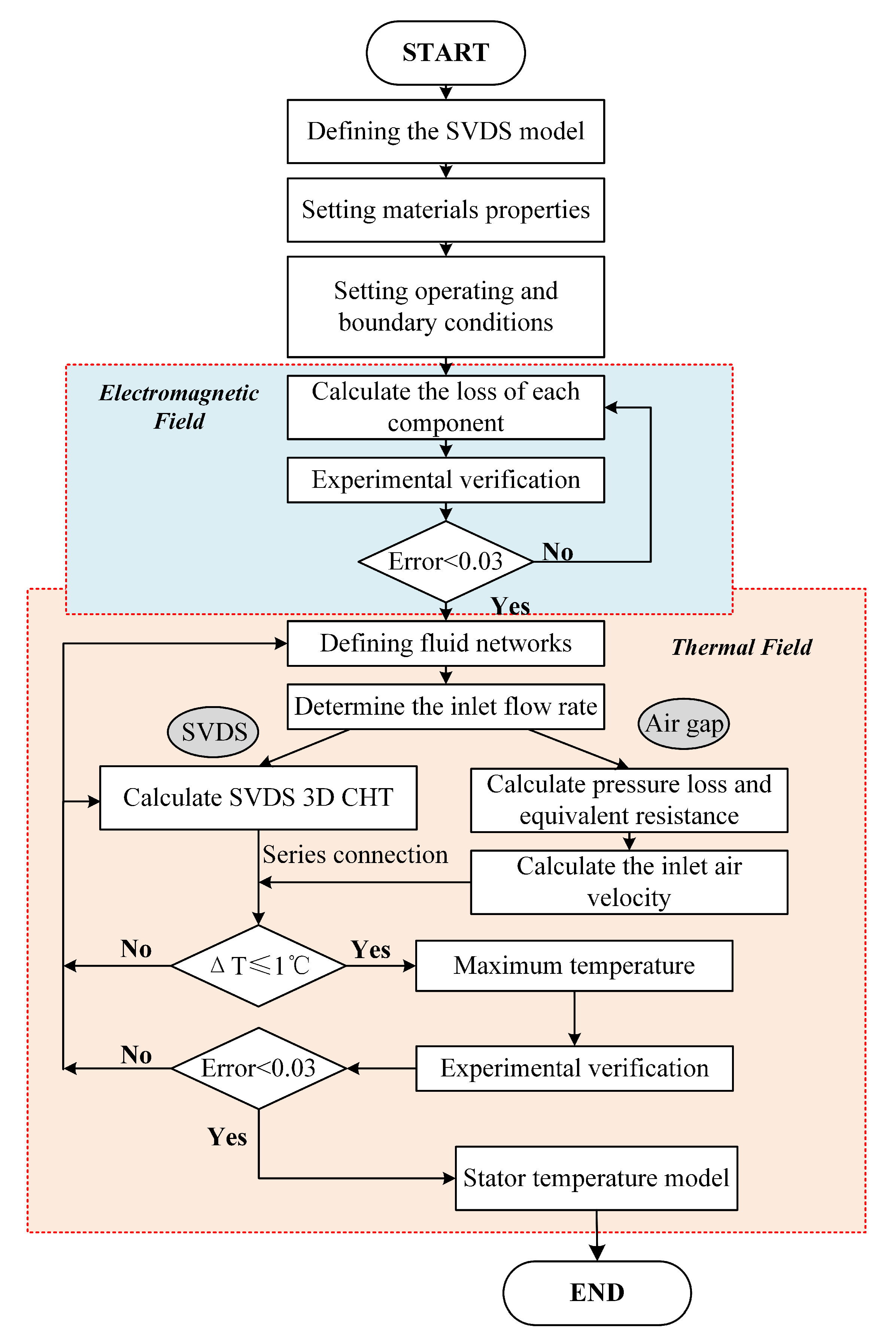
In this section, the single ventilation duct subsystem (SVDS) modelling process and the magnetic-thermal calculations are explained in detail. It is divided into four subsections: model introduction, loss calculation, conjugate heat transfer in SVDS, and fluid analysis within the air gap. The process of establishing the stator temperature model is shown in
Figure 1. The SVDS calculation model and the corresponding boundary conditions are firstly determined by analysing the stator structure, heat generation and removal as well as by appropriate engineering judgement. Following this, the identification of the main objectives and the analysis of the mechanisms are the basis for the loss calculation. After defining the source of heat loss, temperature analysis is conducted. Through analysis of the cooling air flow characteristics and heat transfer characteristics within the SVDS and air gap, the relationship between the model geometry parameters and the object temperature can be established.
2.1. Modelling
In this paper, the considered generator is a wound-rotor, non-salient-pole synchronous generator featuring two poles and 54 stator slots hosting a star-connected three-phase, bar-wound armature winding in a double-layer arrangement. The specifications of the generator are listed in
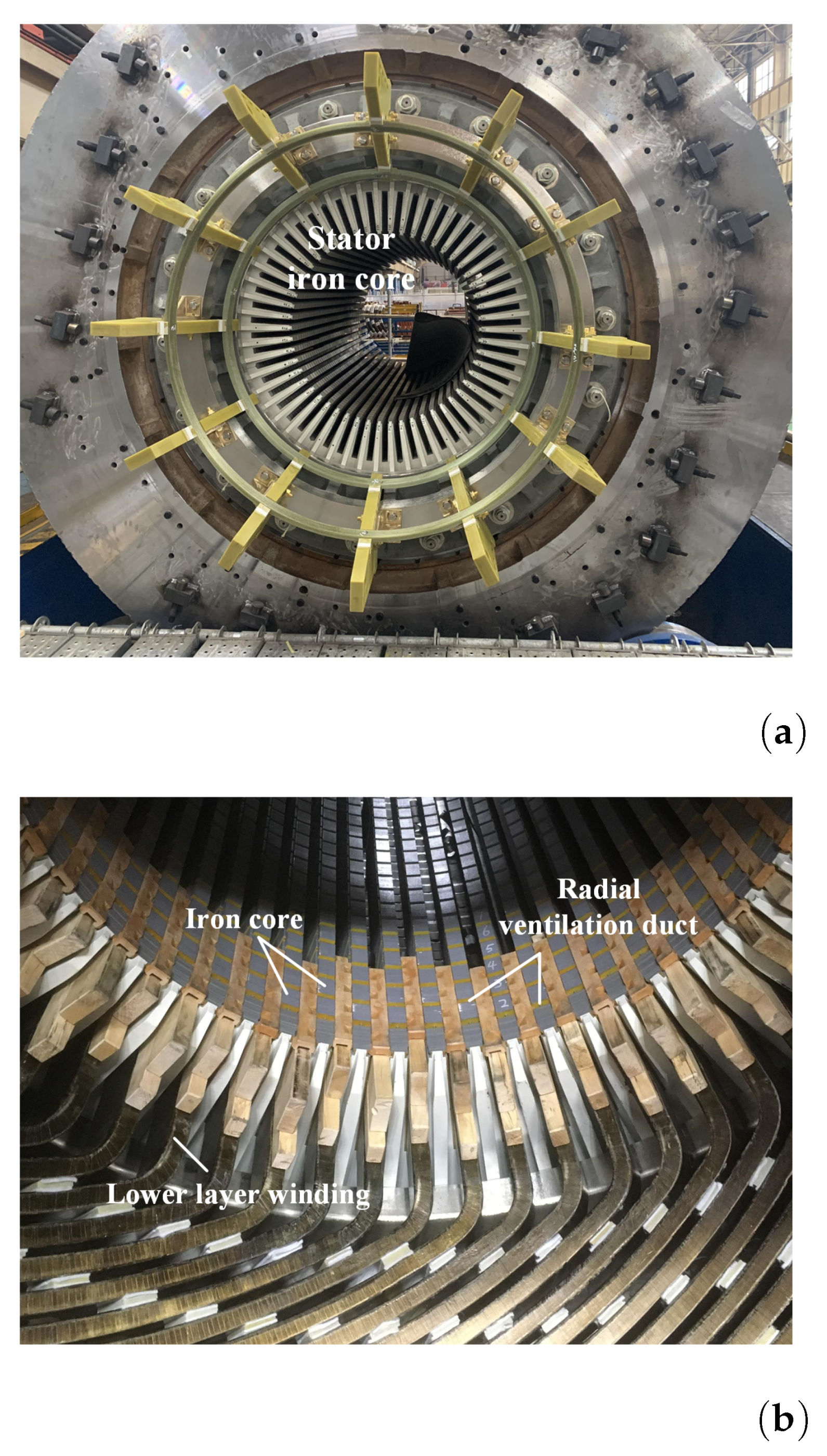
Table 1. The original stator has thirty-three radial ventilation ducts of equal width and which are evenly distributed in the axial direction. The generator adopts a closed loop for cooling, in which coolant air flows from the fan through the air gap to the radial ventilation ducts to cool the iron core and slot windings (Path 1), or the air from the fan directly cools the end windings (Path 2). The heated air from both paths enters the cooler before being recirculated. A schematic diagram of the structure and cooling paths is shown in
Figure 2a.
The research in this paper focuses specifically on Path 1, and assumes that the two paths are relatively independent of each other with no heat transfer between them. Exploiting the symmetry in the circumferential direction of the stator, one stator slot is used as the research domain. The number of conductors per slot is six. One layer of the winding in the stator slot is considered as a homogeneous medium thus ignoring internal temperature differences. Furthermore, it is assumed that the slot is filled with insulating material around the winding. The effects of rotor temperature rise on the air gap cooling air are also considered.
The SVDS is created with the intent to design stator radial ventilation ducts with non-equal widths and non-uniform position distribution. The procedure to design the geometry of each SVDS is based on the fluid state of the air gap, both in terms of heat generation and cooling, in order to achieve a uniform distribution of the stator temperature.
As shown in
Figure 2b, the SVDS is composed of a single radial ventilation duct and its corresponding iron core segment on both sides, together with the insulated wrapped windings. Within the subsystem, heat is generated primarily by winding losses and core losses, while the generated heat is removed from the convective surfaces by the cooling air flowing through the radial vent ducts. As for the arrangement of subsystems, it is assumed that each is closely aligned, maintaining continuity of heat transfer between them.
2.2. Loss Calculation
Loss calculations based on FEM have been extensively researched and applied, and very accurate results can be achieved [
17,
18]. The stator iron losses and winding losses are two key causes of stator heating. The iron losses consist of hysteresis losses, eddy current losses and excess losses [
19], of which are related to the frequency of alternating magnetization and to the amplitude of magnetic flux density. Moreover, the eddy current loss is in direct proportion to the square of the thickness of the stator silicon steel sheet. Once the magnetic field strength and stator materials have been determined, the density of losses is evaluated. The increase in iron core volume means an increase in loss, but it also means an improvement in output power. Regarding the winding copper losses, their value is directly related to the resistance of the winding material and the winding current. Furthermore, it should be noted that the losses themselves are temperature-dependent [
20,
21]. The temperature rise increases the winding resistance, which in turn increases the copper losses. The process will reach a steady state when heat generation and heat dissipation are equal.
In this work, the losses are calculated at the rated power operating condition of the generator. The iron losses are assumed to be constant in the design process. The calculated loss values are then transferred to the thermal model of the stator as the heat sources in the temperature calculation process. The interdependent process of stator temperature and copper losses will converge at a temperature variation of less than 1 °C.
2.3. Thermal and Fluid Analysis
Stator steady-state temperature is the state of equilibrium between heat generation and heat dissipation. The heat generated due to the losses is transferred to the surrounding cooling medium through the contact surface between the solid and the cooling medium and raises its temperature. The heat is removed from the stator with the flow of the cooling medium.
In this case heat conduction and convection are the main heat transfer methods within the stator. The closeness of the contact between the stator components affects the ability of heat conduction from the winding to the core [
22,
23]. Different manufacturing processes and technologies lead to differences in thermal conductivity, for which empirical coefficients are used. The efficiency of thermal convection is related to the local flow state of the cooling air, including the flow velocity of cooling air and the wind resistance in the cooling paths [
7].
The process of simultaneous heat conduction and convection between all the solid components inside this stator and the surrounding fluid region is called conjugate heat transfer [
23,
24]. In the case of three-dimensional heat steady problem for incompressible fluids, this process process is governed by continuity, momentum, and energy equation for a fluid and a conduction equation for body, as follows:
where
are velocity components [
];
is the volumetric thermal expansion coefficient;
and
are solid temperature and ambient temperature [
], respectively;
is thermal diffusivity [
];
is thermal conductivity [
];
is heat source [
].
For the multi-branch stator radial ventilation system, the fluid network is divided into multiple SVDSs and air gap. A diagram of the fluid network is shown in
Figure 3. The pressure loss
H varies with the geometric structure and flow rate
Q as described by [
25]:
The equivalent resistance
Z is:
In
Figure 3,
is the equivalent resistance for the pressure loss caused by the flow in the radial vent ducts, while
is the equivalent resistance for the pressure loss caused by the change in the fluid state of the air gap at the branch due to the subsystem shunt. In order to obtain an accurate temperature distribution, the thermal and fluid analysis within the subsystems is completed by CFD. The aforesaid two resistances are only used to illustrate the impact of the radial vent duct on the fluid state in the air gap. The aim of the fluid network here is to obtain the inlet air velocity of the SVDS.
Within the air gap, the resistances are mainly the ‘along-the-way’ frictional resistance
between the radial ventilation ducts, as well as the deceleration resistance
. The latter is caused by the decrease in the flow velocity within the air gap after the duct shunt, which is directly related to the shunt velocity. With the air gap inlet velocity known, the variation of the wind velocity in the air gap with axial position is shown in
Figure 4.
As the cooling air enters the air gap, it is in the turbulent state and the air velocity increases exponentially [
25]. It rises in the first quarter (up to 400 mm) of the axial position and reaches its maximum value. Subsequently, as the cooling air penetrates further axially within the air-gap, the flow velocity gradually decreases. Meanwhile, due to the shunt of each ventilation duct, there is a stepwise decrease in the flow velocity. The thickness of the boundary layer in the beginning section of the air gap is greater than that of the remaining sections, so there is a tendency for the flow velocity to increase. Furthermore, the cooling air also enters the subsystem at a faster velocity, which has a beneficial cooling effect on the subsystem. However, an increase in flow velocity leads to a thinning of the boundary layer of the air gap, which gradually stabilizes the cooling airflow.
In summary, the temperature within the SVDS can be calculated using CFD based on the 3D conjugate heat transfer and the inlet air velocity from the air gap. Each SVDS is connected in series with the air velocity in the air gap as the medium to form the entire stator temperature model.
3. Surrogate Model
The surrogate model is an approximate of the objective system in a black-box fashion, which establishes direct correlations between inputs and objective outputs without concern for the internal mechanisms of the system [
26,
27,
28,
29]. This facilitates the solution of computationally intensive problems that require a significant amount of time and computational resources.
In the development of the SVDS surrogate model, the design space is first sampled using the isometric sampling method (ISM), and then the sampling points calculated by the combined FEM and CFD approach are used to train RBFNN surrogate model. The model fits the relationship between the geometric parameters and maximum temperature of the SVDS. Finally, the accuracy of the model is verified by non-sampling points data.
3.1. Isometric Sampling Method
The selection of interpolation points in the design space, i.e., the sampling method, has a direct impact on the precision of the surrogate model. The common experimental sampling methods currently used are full factorial design [
8], Latin hypercube sampling (LHS) [
30], Taguchi orthogonal array [
29,
31,
32], Box–Behnken design (BBD), and centre composite design (CCD).
The full factorial design is the most comprehensive and detailed for the design space, but at the same time it is the costliest. Multidimensional and multi-level values aggravate the computational cost. Moreover, when sampling points are projected onto a certain axis, there are many overlapping points, which means that information collected in one dimension can overlap another [
33]. LHS is a hierarchical chunking sampling method that avoids overlapping of sampling in a certain dimension. Since the selection of sampling points in each block is random, this results in many different sampling schemes, and the sampling quality of those sampling schemes varies greatly, requiring screening of the sampling schemes [
33]. BBD and CCD have similar spatial sampling structures. Compared to BBD, CCD is better suited for fitting curved surfaces. Taguchi orthogonal arrays are widely used in industry for robust design and optimization due to their superiority in number of samples [
29,
32]. In this study, a new isometric sampling method is proposed in terms of the number of sampling points and the distance between sampling points.
Isometric sampling method is defined as an equal Euclidean distance between adjacent sample points in the design space. Equal distances between sampling points allow for a uniform distribution of sampling points in the design space, avoiding inconsistent space-filling of each region. At the same time, it is well known that the accuracy of a surrogate model at a non-sampled point is related to the distance of that point from the sampled point. As the distance from the sampled point increases, the accuracy of the model decreases [
28,
33]. The filling of the design space by isometric sampling points is shown in
Figure 5.
In the isometric sampling method, the distance between two known sampled points can be controlled by the number of parameters and levels. The accuracy of the surrogate model at non-sampled points can thus be ensured by setting the number of points to avoid large deviations in the accuracy of the model at different spatial locations.
To assess the distribution of sampling methods in the design space, the maximin metric is used as a criterion, which is one of the most widely-used measures to evaluate the uniformity of a sampling method [
34]. In this study, the following scalar-valued criterion function defined by Morris and Mitchell is used to evaluate the space-filling properties
for the sampling method [
35]:
where
is Euclidean norm between all possible pairs of points in a sampling method
;
is the number of pairs of points in
separated by the distance
;
q is an exponent of this function. The larger the sampling method, the smaller the
q required [
35].
In this sampling plan, the inlet air velocity, radial vent duct width, and iron core segment width are used as design parameters. Regarding the determination of the level values, the upper and lower limits of the parameter interval are taken as the upper and lower levels respectively, and the middle value of the interval is considered as the middle level. For reference, the levels of these three design parameters are shown in the
Table 2.
In the end, the three three-level parameters sampling scheme can be obtained from the ISM, and their corresponding maximum temperatures can be calculated. These sampled data are subsequently used to train the RBFNN surrogate model of SVDS.
3.2. RBFNN Model
Radial basis function neural networks (RBFNNs) are feedforward neural networks with good function approximation performance. Generally, the approximation ability of RBFNN is determined by the centre and the width of radial basis function, the number of neurons and the connection weights [
36]. Under a certain number of neurons, the learning process of neural network is to use the input and output data samples to adjust the connection weights of the network through the predetermined learning algorithm [
37]. The error distribution of the RBFNN model is similar to the radial basis function value, where the error increases with increasing distance from the centre. Furthermore, the width of the function determines the rate of variation of error with the distance. Therefore, the approximate accuracy of the RBFNN model can be adjusted in a uniform manner through the sampling points of the ISM.
In this paper, the RBFNN model of SVDS based on the ISM sampling points is developed to approximate the relationship between the design parameters of the SVDS and maximum temperature. It is a surrogate model to the objective function that is used to optimize the maximum temperature of SVDS.
The radial basis function is a non-negative real function that is radially symmetric at the centre point and the value of which depends only on the distance from the centre point [
33]. Commonly used RBFs use Euclidean distance and Gaussian function. While taking
c as the centre point of the Gaussian function of the hidden layer, the radial basis function
is expressed as:
where
is the maximum distance between centre points and
M is the number of centre points.
The structure of a typical RBFNN includes the input layer, hidden layer and output layer, as shown in
Figure 6. In this paper, the input neurons of RBFNN are the sampling points of the ISM for the inlet air velocity
, radial ventilation duct width
and iron core segment width
of the SVDS, while the output neurons are the maximum temperature
corresponding to each sampling point. The hidden layer is a high-scale dimension, which promotes a linear transformation of input space dimension by computing radial functions in their neurons [
16]. Then the RBFNN surrogate model of SVDS can be trained as follows:
where
represents the connection weights between layers.
4. Optimization Using GA
As a final step of the stator non-uniform radial ventilation duct design, a genetic algorithm (GA) is used to provide optimal design solutions for each subsystem geometry.
GAs are popularly applied to the optimal design of electrical machines due to their effectiveness in solving highly nonlinear problems [
38]. GAs are optimization algorithms that simulate natural evolutionary processes. The algorithm starts with a random initial population, i.e., the first generation of chromosomes. Each chromosome obtains its corresponding fitness value by calculating the fitness function, and this value is used to assess the probability that the next generation will be selected. A small number of chromosomes with optimal fitness values, termed elite children, are transmitted directly to the next generation. “Evolution” is achieved by altering existing chromosomes through crossover and mutation to become the next generation of chromosomes. The process is repeated until at least one stopping condition is met [
39].
Figure 7 gives the optimization flowchart for GA.
In this work, considering the impact of subsystem geometry on temperature, the heat generation within the subsystem can be controlled by the iron core width, while the cooling can be controlled by the width of the radial ventilation duct. This design process takes the width of radial ventilation duct
and the width of iron core segment
as optimization parameters and the stator maximum temperature
as optimization objective. The fitness function is as follows:
where
and
are the total length of the stator and the effective length of the stator, respectively. These two constraints are defined to maintain the power density of the generator and prevent the increase in winding current density due to a decrease in the effective length of the iron core.
5. Experimental Validation
In the experimental process of model validation, this paper introduces the ‘digital twin’ (DT), which can be defined as a computer-based model that can simulate, emulate and mirror physical entities. A DT is the virtual counterpart of a physical entity. It follows the operation mechanism of its physical twin to optimize its function [
40]. In this paper, a DT based on EM FEM and CFD model was established for the electromagnetic and thermal fields of a turbo-generator to simulate the loss and temperature distribution of the stator physical entity. After correcting the errors in the loss and temperature characteristics between the DT and the physical entity, the subsequent optimization of the design and verification of the results can be performed on the basis of the DT.
To ensure the consistency between the simulation and experimental result, the initial conditions of the SVDS temperature model were set based on the experimentally measured values. The total flow rate and air gap inlet air flow rate were measured with a pre-positioned Pitot tube to obtain the initial cooling capacity of the cooling air. Meanwhile, the surface resistance of the iron core laminations and copper windings were measured to obtain accurate losses. The results show that the calculated iron and copper losses are 56.6 kW and 67.1 kW, respectively, which are 0.23% and 0.15% different from the experimentally measured results. The instrumented turboalternator stator is shown in
Figure 8.
To measure the stator temperature, the temperature sensors were placed in the stator winding, stator teeth and stator yoke. The sensors were positioned at the inlet (A) and outlet (E) of the air gap, and at 1/4 (B), 1/2 (C) and 3/4 (D) of the stator axial sections. The schematic diagram of the sensor placement position is shown in
Figure 9. The measurements were taken at rated power conditions and 0.8 power factor. The generator ran for multiple hours to ensure thermal steady-state conditions were reached.
The comparison between the stator temperature calculations and the experimental results is given in
Figure 10. The temperature of the upper and lower layer windings of the stator as well as the stator teeth have a similar trend, with an initial decrease followed by an increase in temperature with axial position. The temperature trend in the axial direction can be explained by the variation of the air velocity of the cooling air in the air-gap, where the rapid flow of the cooling air means that heat is carried away from the heat source with high heat transfer efficiency. However, the measured temperature of the stator teeth at point A fails to conform to this trend due to the fact that the initial inlet temperature of the cooling air has a more pronounced effect on the temperature of the core laminations rather than the winding.
The temperature distribution of the SVDS and fluid flow behaviour of cooling air are shown in
Figure 11. The maximum temperature of the stator appears on the windings, not only because of the high heat density of the windings, but also because they are surrounded by insulating materials, which makes heat dissipation difficult. Compared to the lower layer winding, the upper layer winding dissipates heat better because it is closer to the cooling air in the air gap. The temperature of the stator iron core increases in the direction of fluid flow. This is because as air flows more and more heat is transferred to it, resulting in a decreasing temperature difference between the cooling air and the solids, and thus the cooling capacity also decreases.
As for the shunting of cooling air, a portion of the cooling air enters the radial ventilation duct from the air gap, cooling the stator teeth, windings, and stator yoke in turn, and finally taking the heat away from the back of the stator. As the hydraulic diameter of the fluid decreases, the cooling air entering the radial ventilation duct flows rapidly through the sides of the insulation-wrapped windings. From the above results and the foregoing analysis, the flow state of the cooling air in the SVDS is consistent with the analysis of the fluid network model.
6. Results
6.1. Comparison of Sampling Methods
From the maximin metric and scalar-valued criterion function, the space-filling properties of the isometric sampling method (ISM) and other common sampling methods were obtained.
Table 3 shows the corresponding
for the number of different parameters at three-level for several sampling methods. The smaller the value of
, the better the space-filling properties of
X were. The Latin hypercube sampling (LHS) used for comparison in this table is the scheme that was optimized in accordance with the scalar-valued criterion function. Face-centred central composite design (FCCD) is the special case where the central composite design (CCD) was at alpha equal to one moment, such that all sampling points of the sampling method used for comparison were between the unified upper and lower limits.
The sampling points of full factorial design, Taguchi orthogonal array and FCCD were the same at the two three-level parameters. At three three-level parameters, Box–Behnken design (BBD) and ISM had a very similar distribution of sampling points, and ISM can be seen as a translation and symmetry of the BBD. For the four parameters, Taguchi orthogonal array exhibited the smallest because it had the smallest number of samples. Furthermore BBD, FCCD and ISM show similar characteristics.
From the consistency of the distance between sampling points, BBD and ISM were more advantageous than FCCD. ISM provided a somewhat better description of the space than BBD when considering the sampling method for the edge of the design space.
6.2. RBFNN Surrogate Model
Based on the ISM sampled points, an RBFNN surrogate model reflecting the direct relationship between the stator design parameters and the maximum temperature was developed. It was used as an alternative to the optimization objective function for iterative calculations in the optimization algorithm and to find the optimal design parameters.
Regarding the accuracy of the surrogate model, it was ascertained that the model could precisely describe the output characteristics of the physical entity at the sampled points. As for the accuracy of the model at non-sampled points in the design space, the model needed to be detected and analysed through a validation dataset to determine whether its performance needed to be further improved. Therefore, this study selected and computed a set of non-sampled points in the design space to serve as a validation dataset.
Considering that the distance between non-sampled and sampled points is a function of model error, the selected validation points were located at the position of maximum model error and are uniformly distributed in the design space. It should be noted that the union of the selected validation points and the sampled points was the total combination of design parameters in the design space.
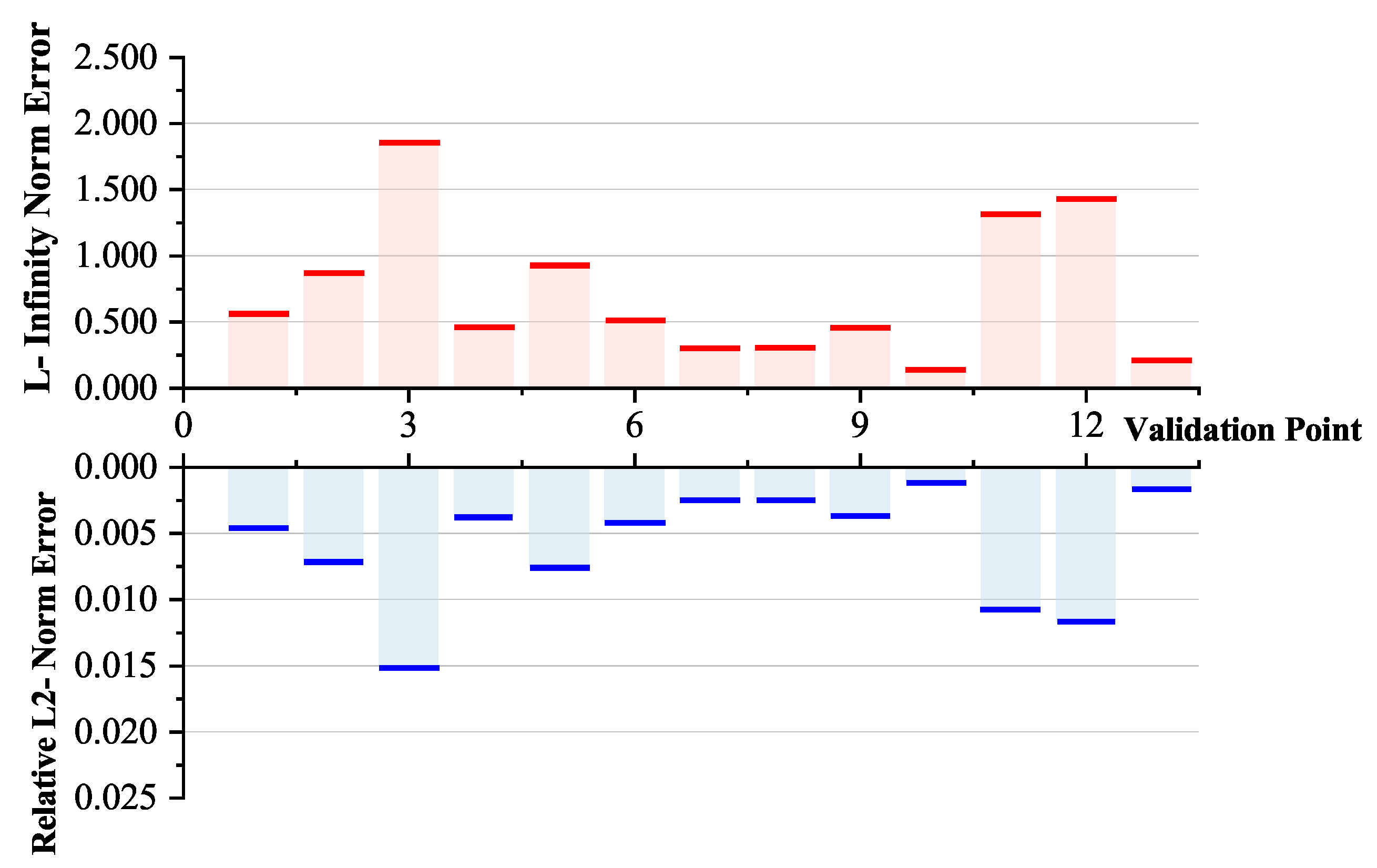
The process of model validation began by using the design parameters from the validation dataset as input to the constructed surrogate model, and then comparing the results obtained from the model calculations with the original results in the dataset. The L-infinity norm error and relative L2 norm error for each validation point are shown in
Figure 12. Three of the points in the results performed slightly below the overall level, and although the accuracy could be improved by continuing to train the surrogate model by interpolating point fills, this paper will not further improve the performance of the model as its errors were in line with the initial expectations.
The accuracy of the model was also verified by comparing the temperature calculated based on the surrogate model with the experimental results, since the design parameters in the original design were not included in the sampling points of the ISM.
6.3. Optimization Results
When the RBFNN as a surrogate model of the optimization objective function was successfully developed and verified for accuracy, a genetic algorithm (GA) was next used to find the optimal ventilation ducts’ design scheme for the stator geometry. Under pre-set constraints, the width of the iron core segment and the width of the radial ventilation duct of SVDS were optimized within the design space to reduce the maximum temperature of the stator.
Figure 13 shows the iron core segment widths and radial ventilation duct widths for each SVDS (33 in total) before and after optimization. The grey dots in the figure represent the uniform duct dimensions within the original alternator of
Figure 8. It was evident from the optimization results that the trend of the iron core segment widths along the axial direction was opposite to the trend of the radial ventilation duct widths. The width of the iron core segment increased in the initial quarter of the axial direction, while the width of the radial ventilation duct continued to decrease. Compared to the original design, the maximum width of the optimized iron core segment increased by 4.6 mm and the minimum width of the radial ventilation duct decreased by 0.78 mm.
Regarding the cause of this variation in width, it can be rooted to the state of flow of the cooling air in the air gap, which increased in the initial quarter of the axial direction, as discussed earlier on in
Figure 4. Correspondingly, its cooling capacity also rose in the initial segment, and the heat in the stator was efficiently dissipated. As a result, this initial section placed wider iron core segments and more heat generation sources than the remaining section. At the same time, the width of the radial ventilation ducts was reduced in order to avoid excessive consumption of the cooling capacity in the initial section, so that more cooling air could flow to the places where the heat was not easily dissipated (i.e., towards the back section).
Indeed, in the original design with uniform duct design, the initial section consumed a large amount of cooling air, which significantly reduced the temperature, but left the remaining back-sections with insufficient cooling capacity which translates to a temperature rise therein (and also a temperature gradient).
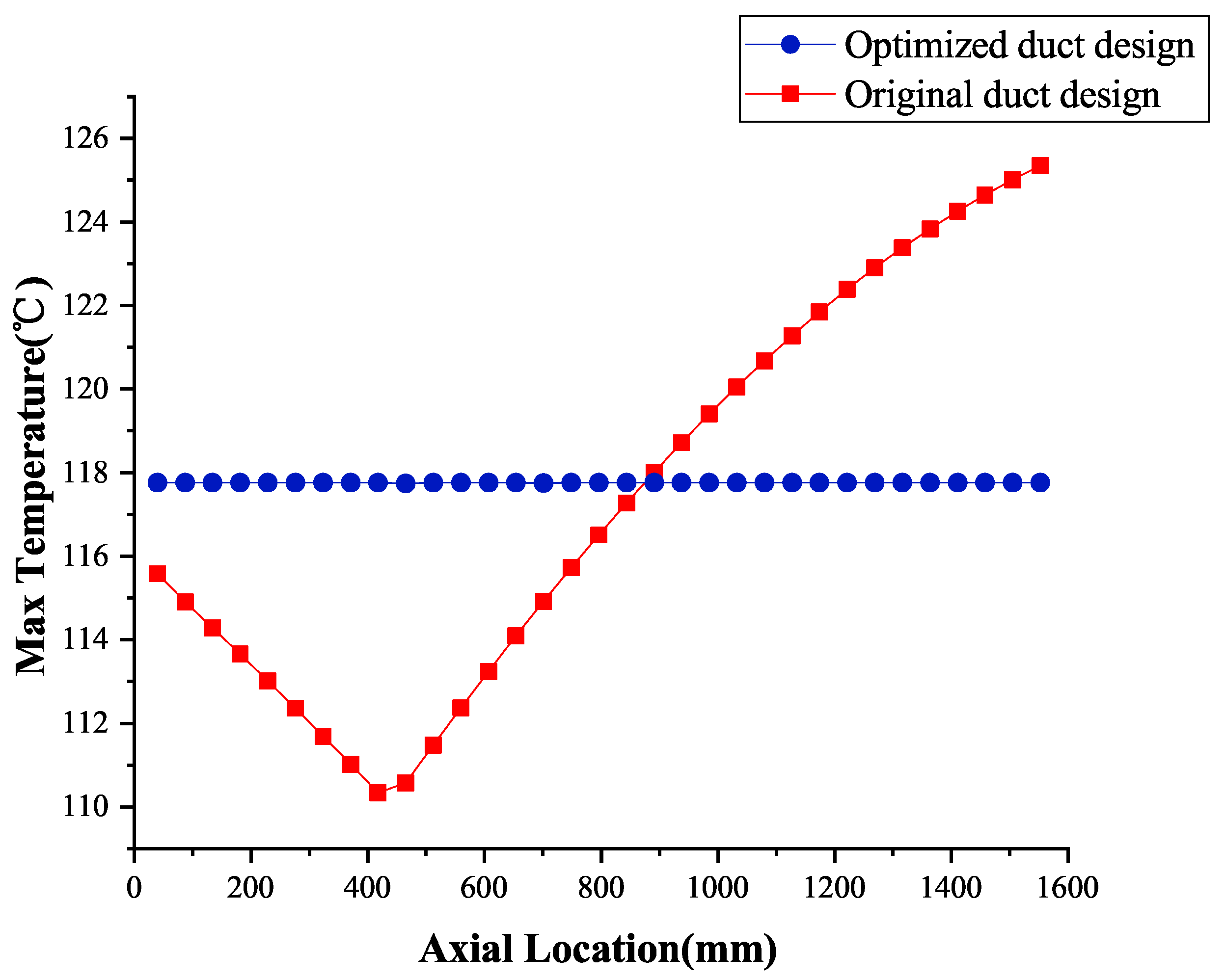
Figure 14 presents the maximum temperature for each axially distributed SVDS before and after optimization. In the original design, the axial temperature difference reached 15 °C, while with the optimized design the temperature was uniformly distributed at 117 °C. The maximum temperature of the stator was thus reduced by a significant 7.6 °C. Considering that the maximum temperature is of key importance to electrical machine reliability, a uniform temperature distribution is beneficial to machine performance.
8. Conclusions
In this paper a novel design methodology of the stator non-uniform radial ventilation ducts for large high-power MW-class alternators is presented. Through the design of the specific geometries and axial position of each duct, the maximum stator temperature is reduced while markedly narrowing the differences in the axial distribution of the stator temperatures.
To simplify the model complexity and reduce the computational volume of the model, the stator is axially decomposed into several SVDSs connected in series during the numerical-based electromagnetic and temperature analysis calculations. The dimensions of the SVDS are optimized by NSGA II and RBFNN surrogate model according to the dependence of the cooling effect and the heat generation of the stator on the geometry. The ISM method that trade-offs the number of numerical calculations with the accuracy of the fit is proposed in this paper to improve the efficiency of the RBFNN model approximation. The optimization with the proposed method resulted in a 7.6 °C reduction in the maximum temperature and a more uniform axial temperature compared to the original 15MW baseline design.
Finally, the accuracy of the SVDS and the RBFNN surrogate model were experimentally verified on an alternator. The stator non-uniform ventilation ducts design methodology proposed in this paper provides an integral and comprehensive design scheme for the analysis of electromagnetic-thermal coupled fields in high-power MW-class alternators. It not only presents novel solutions for model simplification and the surrogate model sampling, but also significantly reduces the computational cost of the entire procedure.


