Article

Integrating a Heat Sink into Concentrated Wound Coils to Improve the Current Density of an Axial Flux, Direct Liquid Cooled Electrical Machine with Segmented Stator

by
Robert Camilleri
1,* and
Malcolm D. McCulloch
2
1
Institute of Aerospace Technologies, University of Malta, MSD2080 Msida, Malta
2
Department of Engineering Science, University of Oxford, Oxford OX13PJ, UK
*
Author to whom correspondence should be addressed.
Energies 2021, 14(12), 3619; https://doi.org/10.3390/en14123619
Submission received: 11 March 2021 / Revised: 10 April 2021 / Accepted: 20 May 2021 / Published: 17 June 2021
(This article belongs to the Special Issue Thermal Management in Electrical Machines)

Abstract

:
This paper proposes a new construction with a heat sink integrated into the concentrated wound coils of an axial flux, direct liquid cooled electrical machine. A preliminary assessment of the effectiveness of the heat sink and its position is made using computational fluid dynamics. Lumped-parameter thermal models are also developed, thus allowing accurate comparison of the thermal profile of the two constructions. Following experimental calibration of the model and thermal validation, the temperature profile of the new construction is compared to that from a traditional concentrated wound coil. The model is then used to estimate the effect of the new construction on the current density of the stator windings. The paper demonstrates that for an axial flux motor run at a typical operating point of 300 Nm and 1500 rpm, the maximum temperature is reduced by 87 K. The current density can be increased by 140% before the limiting maximum coil temperature is achieved.

1. Introduction

The demanding requirements of the electric powertrain has resulted in a continuous research efforts to improve the current densities of electrical machines. High current density electrical machines require the active material to be as small as possible. However, as the machine designs become compact, space becomes more valuable. The manufacturing of small stator windings is challenging. Concentrated windings have been shown to offer a significant reduction in active material for machine sizes smaller than 300 kW [1]. Compared to traditional machines with one slot per pole and per phase, concentrated windings achieve reduced Joule losses, therefore improving the efficiency of the machine [2]. Concentrated windings also offer a high slot-fill factor, low cogging torque and greater fault tolerance [2]. Their simple manufacturing process lowers manufacturing costs [3]. This makes concentrated windings the preferred type for high current density electrical machines.
However, concentrated windings suffer from a severe temperature gradient [4]. Furthermore, the maximum winding temperature was shown to provide a major limitation for increasing the current and torque densities of the machines. The I2R losses in electrical machine windings generate heat. If not extracted, this raises their temperature. Since the winding insulation is rated for a maximum operating temperature and degrades by the Arrhenius chemical reaction [5], high temperatures in the stator windings limits the life and rating of the machine. An increase in machine current density requires both the electromagnetic and thermal aspects of the machine to be optimized [6]. This paper aims to improve the current density by developing a new construction of a concentrated winding in which a heat sink is integrated into the coil. This allows for a more effective cooling of the inner coils by reducing the thermal resistance. Hence, the temperature in the windings is reduced. For the same maximum temperature, the current flow through the windings can be increased.
This paper uses the geometry of the permanent magnet Yokeless and Segmented Armature (YASA) electrical machine as a case study. This machine is derived from the NS Torus-S topology with external rotor and internal stator. The machine design has its stator yoke removed and the pitch of the teeth enlarged. This allows for high fill factor short end winding concentrated coils with square cross sectioned wire wrapped around the individual stator poles, thus reducing the iron in the stator by around 50%. The stator is enclosed in a casing allowing liquid coolant to be injected into the stator, in direct contact with the windings, as shown in Figure 1. When compared to other axial flux machines, the YASA machine has its torque density increased by around 20%, with a peak efficiency over 95% [7]. Studies of the flow distribution and the convective heat transfer in this machine have been reported in [8,9], respectively. This architecture has received increasing attention, and several variants are now found in the literature [10,11,12,13,14,15]. While traditional air cooling and indirect liquid cooling are found to reach current density limits between 15–20 A/mm2 [16], direct liquid cooling reduces the thermal resistance along the thermal path, enabling lower winding temperature or higher current densities. Methods for reducing the thermal resistances between the electrical coils and the coolant have been the subject of other publications [17].
Semidey and Mayor presented a micro-channel integrated between two tooth-coil sides within the same slot [18]. They show that such technology could improve the current density from 15 A/mm2 to 25 A/mm2 under steady state conditions. Reinap et al. produced channels within laminated windings so as to enhance forced air convective heat transfer from the machine coil. The authors reported that this allowed them to reach current densities as high as 30 A/mm2 [19]. Wohlers et al. [20] presented a novel cast coil which integrateed channels to allow direct liquid cooling on every individual conductor. When tested with deionized water, a current density of up to 100 A/mm2 was shown to be achievable. Deionized water has a much larger specific heat capacity, lower Prandtl number, and lower viscosity than oil, thus leading to a higher Reynolds number, which in turn provides higher heat transfer coefficients. However, it also has a tendency to form ions and therefore further action is required to maintain the low conductivity of the fluid.
This paper presents a means for improving current density by addressing the heat transfer from electrical machine windings, and is organized in the following manner. A conceptual development of the new windings with integrated heat sink is presented in Section 2. A preliminary assessment of the concept using CFD is provided in Section 3. This exercise is used not only to gauge the heat sink effectiveness but also to determine its position within the windings for maximum impact. While CFD models often provide insight into the problem and foresight to improve future designs, this is time consuming. Therefore, the paper also develops a Lumped Parameter (LP) thermal model in parallel. The LP model is used to compare the temperature profile of the traditional windings and the new winding constructions, thus investigating the effectiveness of the new design. The LP model is presented in Section 4. The model is calibrated and validated experimentally in Section 5. Section 6 presents the test results, while a discussion and conclusion are presented in Section 7.

2. Conceptual Development of the Windings

2.1. The Impact of Winding Construction on Current Density

The current density of an electrical machine can be shown to be heavily dependent on both convective and conductive heat transfer from the windings [21]. This can be reflected by Equation (1).
J = T s T f 1 h A + x k e q A . 1 ρ T V c 0.5
where Ts is the stator temperature and Tf is the coolant temperature. 1 h A is the convective heat transfer where h is the convective heat transfer coefficient and A is the heat transfer area. x k e q A represents the conductive term where x is the stator thickness and k e q the equivalent stator conductivity. ρ T is the electrical resistivity of the coil and V c is the volume of the coil. It can be shown that while the convective heat transfer term can be improved by switching to more effective cooling such as direct liquid cooling [11], further increase to the current density will be hindered by the thermal conductivity of the coils. Although copper wire has a thermal conductivity of 350 W/mK, it is coated by a polyamide/imide insulation which has a very low thermal conductivity (<1 W/mK). Furthermore, the coils are grouped together and epoxy may sometimes be injected to fill in the airgaps. This gives the coils a heterogeneous property with the overall equivalent conductivity reduced to between 1–3 W/mK [22]. This, in turn limits the current density. Despite the fact that that there have been efforts to improve the thermal conductivity of epoxy [23], it does not produce the desired step increase in stator current density. Therefore, new designs are required.

2.2. A New Construction with Integrated Heat Sink

In direct liquid cooled machines, heat generated in the windings is transferred radially outwards from one winding layer to the next, until it is eventually absorbed by the coolant. The inner winding layers experiencing the longest thermal path (and highest thermal resistance) suffer from the highest temperature in the windings. Therefore, to avoid damage to the electrical insulation of the inner coils, the current density of the machine has to be capped. The new construction presented in this paper stems from the need to bypass the chain of inter-winding thermal resistances that the inner coils are faced with by introducing a heat sink within the electrical conductors. This allows heat to travel along the heat sink, maintaining the inner coils at lower temperatures. Figure 2 shows how the new construction is formed by integrating a heat sink into traditional concentrated windings. To assess the effectivity of the novel construction, a CFD model was developed.

3. A Preliminary Assessment of the Concept through CFD Modelling

3.1. CFD Analysis of the Machine Windings

CFD modelling of electrical machine windings is complex and challenging. Difficulties mainly stem from the difference in scale between the current conductor and the insulation. The modelling of individual insulated conductors requires an inefficient fine-meshing process [24] which adds complexity, computational effort, and long solution times. To simplify the problem, the windings are sometimes treated as a homogeneous material with equivalent thermal properties [25,26,27,28,29,30]. Yet, this approach lacks detail. The technique is also unable to analyze new designs such as the construction with an integrated heat sink proposed here. In direct liquid cooled machines, the coil is surrounded by coolant. Hence the heat generated by the individual pole pieces is transferred radially across the coils and dissipated into the coolant. Therefore, by neglecting axial heat transfer, the concentrated coil is simplified into radial layers, as shown in Figure 3. The windings used here are AWG14, hence each turn is considered as a layer. Adjacent winding layers are then interfaced to each other through a thermal contact resistance. The CFD process is described in [31].

3.2. Setup of the CFD Simulation

The computer-aided design (CAD) geometry of a single pole piece with representative flow domain highlighted in Figure 1 was developed. The CAD model was developed for traditional concentrated windings and a new construction, as shown in Figure 4. The simulation was run with the synthetic dielectric coolant Opticool. The properties of fluid are found to vary significantly with temperature and are described in Table 1. The pole pieces were modelled using the thermal properties of soft magnetic compound (SMC) iron thermal and copper coils as shown in Table 2. The boundary conditions were set as shown in Figure 5, having an inlet flow rate, and coolant temperature and an outlet gauge static pressure of 0 Pa to simulate the flow-out direction. This was used as reference by the Autodesk CFD Simulation software (Autodesk, San Rafael, CA, USA) to compute the pressure upstream [32]. Heat loads were applied to the pole piece components.
The 3D mesh was formed from tetrahedral elements with minimum refinement length set to 0.5 the maximum size set to 1.8 at the surfaces. The boundary layer mesh was made of 15 layers with a factor of 0.75 and gradation of 1.15. A grid sensitivity analysis was performed. The final mesh, shown in Figure 6, consisted of 3.6 M elements. The authors experimented with fixed and temperature-dependent coolant properties, conjugate and segregated simulations and different advection schemes, which govern transport quantities such as velocities and temperature through the flow domain. Details of the advection schemes are provided in [32]. The oil coolant was found to produce low Reynolds numbers across all channels (10 < Re < 200), and therefore the simulation was run with a laminar model. For simulations on the new geometry, a typical thermal contact resistance of 0.2 K/W was adopted between the heat sink and the adjacent windings. The model was found to be most accurate when a conjugate, laminar model using ADV 4 settings and temperature-dependent coolant properties. The simulation was repeated with tighter mesh settings until the temperature variation of the pole piece was <2%. A solution was produced in approximately 12 h.

3.3. Post Processing of the CFD Model

Post processing of CFD models allows the user to visualize the results of the simulation. This provides the thermal designer with the insight of these mechanisms and the foresight to improve the design. The CFD model was used to compare the temperature maps of new construction and traditional concentrated windings. The effectiveness of the heat sink for different locations within the winding layers was also investigated for various loads. Figure 7 shows an example of a temperature map of the windings. It can be seen that when applied to direct liquid cooled machines, traditional concentrated windings experience the highest temperature at the inner windings and the iron. The effectiveness of the heat sink on the windings was found to be highest when it was mounted between the inner and middle windings. The design with the integrated heat sink between the inner and middle windings was therefore the design of choice.

4. LP Modelling of Concentrated Windings

While CFD models provide an accurate visualization of the concept, they are computationally intensive. To enable an efficient way to compare the temperature profiles between the conventional construction and the new geometry, a lumped parameter (LP) thermal model was also developed in parallel.

4.1. Definition of the Thermal Network

The performance of the LP model is as good as the definition of the thermal network, the location of the temperature nodes, and the governing equations. The LP model uses the same heat flux assumptions described earlier for the CFD analysis. Thus, the windings were simplified into layers. A temperature node was placed on the iron bobbin and each winding layer. For symmetrical liquid cooling, the pole piece can be thermally modelled by four nodes: one on the iron and one on each of the three winding layers, as shown in Figure 8. Each node within the model has a uniform thermal capacitance defined by the product of the volume, specific heat capacity and density. Each thermal node was linked to its neighboring node through thermal resistance Rth. A MATLAB script (Mathworks, Natick, MA, USA) was developed to solve the differential equations of the LP model using the 4th-order Runge Kutta method.

4.2. Adjusting the LP Model for the New Construction

The LP model was adapted for the new construction with integrated heat sink. In this case, a new thermal node for the heat sink was introduced between the inner and middle windings. The heat sink node had thermal capacitance CHS, and was connected to the adjacent windings through the thermal resistances R2 and R2. The heat sink node was also connected to the fluid through an additional thermal resistance RFin. Figure 9 shows a schematic of the LP model for the new construction.

5. Experimental Work

5.1. Manufacturing the Prototypes

Concentrated windings are simple to manufacture. Moreover, segmented stators offer an additional benefit during the design and testing phase. as they allow for the thermal analysis of single pole pieces [26]. A traditional concentrated winding and a prototype of the new construction were manufactured. Each was instrumented with temperature sensors. To manufacture the prototypes, a winding machine, shown in Figure 10, was used. The machine is made of two main components: a lathe with controllable speed and modified jaws to grab the pole pieces, and a copper reel clamp coupled to a fixed speed electric motor via a clutch with controllable slip. During the winding process, the copper was subjected to tension caused by the electric motor holding the winding reel and the lathe rotating in opposite directions. The tension was adjusted by adjusting the slippage on the clutch. A mold for the bobbin was designed and 3D printed, thus allowing the jaws of the lathe to clamp the fragile bobbin without damaging it. The pole piece was wound with a square copper wire of size AWG14 (1.62 mm), at a tension of 30 N. To improve their mechanical rigidity and provide ingress protection, pole pieces are sometimes treated with epoxy encapsulation. Common techniques include vacuum pressure impregnation (VPI), epoxy painting or coating in varnish or epoxy. VPI requires a specialist vacuum chamber which sucks out the air and forces epoxy into the coil to fill the voids between the windings. On the other hand, painting and coating require no specialist equipment. Epoxy painting was adopted for this paper: a viscous layer of filler Stycast epoxy was painted on each winding layer before the next layer was wound. The properties of Stycast epoxy are shown in Table 3.
Thermocouple sensors were mounted midway in the coil height, on each side of the pole piece, during the winding process; between the iron and the first copper layer, between the first and second copper layers, and between the second and third copper layers. In the manufacturing of the new construction, the flat state of the heat sink was designed and produced from a copper sheet. The CAD geometry of the heat sink is shown in Figure 11. While very thin sheets would limit the heat transfer capacity, thick sheets were found to be very brittle when worked upon. The compromise of a heat sink thickness of 0.1 mm was established. The heat sink was added to the windings after the first layer. Winding was then continued, as shown in Figure 12. The copper flat sheet was later folded into the heat sink. The prototype, traditional, and new constructions are shown in Figure 13.

5.2. Test Setup

To measure the temperature profile across the instrumented pole pieces, a representative experiment was set up. Each instrumented pole piece was mounted on a plastic base and assembled in a test box. The test box was also fitted with two non-energized half poles, one on each side of the test piece, thus recreating the flow channels between the pole pieces, as shown in Figure 14. The plastic base acts as a thermal insulator and limits the heat transfer to the test box. The copper windings and the SMC iron bobbin were each connected to a DC power supply and energized separately, thus simulating the respective Joule losses. The iron losses were kept at 20% of the total pole piece losses, as per manufacturer recommendations. Current meters and differential voltage probes were used to measure the current and voltage supplied to the windings. The heat input was calculated as the product of the current and the voltage. The coolant was re-circulated from a reservoir into the test rig, and then pumped through a heat exchanger, expelling heat to ambient. The reservoir was also fitted with a heating element to control the inlet temperature of the fluid into the test section. The power input to the coolant heater and hence the coolant temperature was regulated through a transformer. The flow rate was regulated using a globe valve and measured using a variable area flow meter, as shown in Figure 15.

5.3. Calibration of the Thermal Models

Calibration processes are typical to LP techniques [28,29,33]. These were achieved by running a number of transient experiments, whereby the coil was provided with a short heat input. The temperature of the coil was measured. The first data set was used to fully characterize the thermal resistances of the LP model. The remaining experiments were used to verify the calibration parameters of the model at different conditions. During these tests, the oil flow was set and run at a fixed flow rate. The heat input to the winding and the iron were set and energized simultaneously. The increase in the temperature of the windings was monitored and recorded. The windings were de-energized to capture the cooling curve of the pole piece. The heating and cooling portions allowed us to check the heat capacity used in the model. Details of the parameters of the transient calibration of the traditional concentrated windings and the new construction are shown in Table 4 and Table 5, respectively.

5.4. Steady State Thermal Validation of the Windings

A series of steady state measurements were also recorded. These were intended to capture the temperature gradient across the concentrated windings. Steady state tests were run for approximately two hours to ensure that steady-state conditions were reached. The experimental procedure was repeated for both the traditional and the new construction. Details for the steady state experiments are shown in Table 6 and Table 7.

6. Test Results

6.1. Transient Calibration of the Model

An example of a thermal characterization chart of conventional concentrated windings is shown in Figure 16. The inter-winding thermal resistances and thermal capacitances of each winding layer and SMC bobbin were identified by fitting the model to the first experimental data. The calibrated parameters of the conventional concentrated windings are shown in Table 8. The calibrated parameters of the new construction are shown in Table 9.

6.2. Steady State Temperature Profile of the Windings

The steady state experiment established the temperature profile across the windings. The thermal models of the traditional and the new construction were compared to the experimental measurements. An example is shown in Figure 17. The plotted temperature profiles were referenced to temperature sensors mounted along the line AA’ shown in Figure 14. The calibrated models were found to match the measurements to within 3%.

7. Discussion and Conclusions

Having established the thermal characteristics of the thermal models and validated their accuracy, the LP models were used to get an accurate comparison of the temperature profile for the traditional pole piece and for the new construction for a range of coil power ratings. The heat load in the coils and the iron were increased proportionally until the hotspot temperature of the AWG 14 square magnetic wire with an insulation IEC60085 rating of 250 °C was reached. A plot of current density vs. maximum coil temperature is shown in Figure 18. The new construction was found to reduce the maximum temperature by 87 K. The new construction was found to improve the steady state current density of the coil by approximately 140% before the same hotspot temperature of the conventional construction was reached. It should be noted that this analysis is limited to matching the maximum temperature in the overall pole piece. Due to the heat sink design, the hotspot was now shifted to the iron.
This paper presents a new construction for concentrated windings. The new construction integrates a heat sink between the inner and middle winding layers, creating a thermal bypass across the poorer conductivity of the adjacent winding layers. The new construction was found to reduce the maximum temperature by approximately 87 K at a typical operating point of 300 Nm and 1500 rpm. The reduced temperature can offer three advantages to the electrical machine, namely:
  • A reduction in coil temperature and therefore an increase in the winding life time.
  • The reduction in coil temperatures will also produce a reduction in the winding resistive losses and therefore an increase in machine efficiency.
  • When operated at its maximum operating temperature, the current density of the stator is increased.
This paper applies the new construction to an AFPM machine with a direct oil cooled segmented stator. However, the benefits of the new construction are not limited to a specific machine and can be applied to various machine topologies with concentrated wound pole pieces. For example, switched reluctance (SR) machines are of great interest to the automotive sector as they are fault tolerant, cost effective, and do not make use of permanent magnets. However, SR machines suffer from a torque density that is about 50% lower than that achieved by PM machines, [34]. This new winding construction may hence be adapted to address such a challenge.
The author is aware that further analysis is required with respect to the electromagnetic effects and eddy losses of the integrated heat sink, cost analysis, and testing with a full motor. This is beyond the scope of this paper, which provides a route for improvement in current density, and will be investigated in a separate study. Further improvement of the heat sink, for example, through micro-features, is also possible, and is also the subject of an ongoing investigation.

Author Contributions

Conceptualization, R.C.; methodology, R.C.; software, R.C.; validation, R.C.; formal analysis, R.C.; investigation, R.C.; resources, R.C.; data curation, R.C.; writing—original draft preparation, R.C.; writing—review and editing, R.C.; visualization, R.C.; supervision, M.D.M.; All authors have read and agreed to the published version of the manuscript.
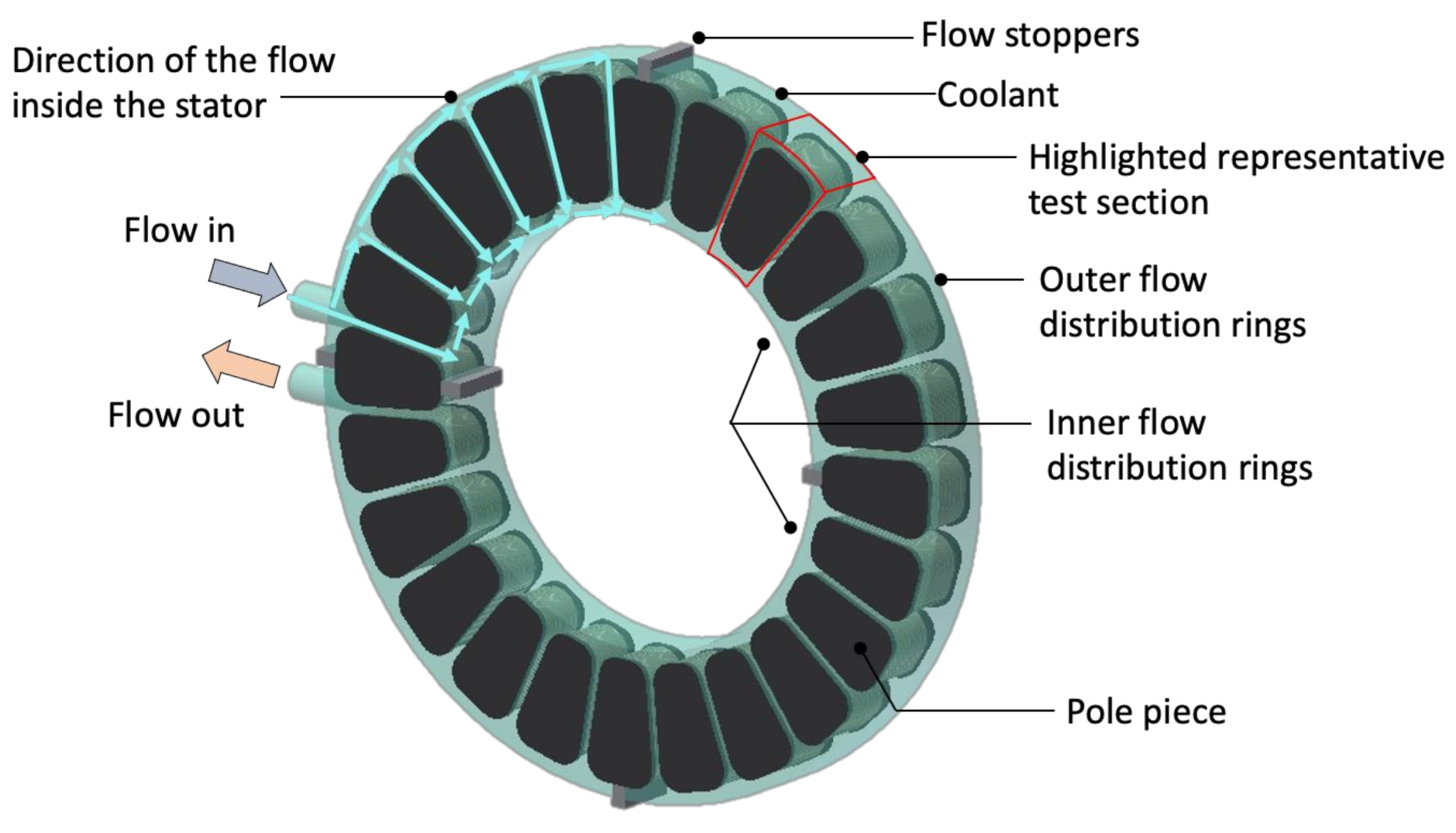
Funding

This research received no external funding.

Institutional Review Board Statement

Not applicable.

Informed Consent Statement

Not applicable.

Conflicts of Interest

The authors declare no conflict of interest.

References

  1. Potgieter, J.; Kamper, M.J. Evaluation, Application and Comparison of a Double-Rotor Toothed Toroidal Wining Wind Generator Over a Wide Power Range. In Proceedings of the International Conference on Electrical Machines (ICEM 2014), Berlin, Germany, 2–5 September 2014. [Google Scholar]
  2. Cros, J.; Viarouge, P. Synthesis of High-Performance PM Motors with Concentrated Windings. IEEE Trans. Energy Conv. 2002, 17, 248–253. [Google Scholar] [CrossRef]
  3. Dajaku, G.; Gerling, D. Low Costs and High-Efficiency Electric Machines. In Proceedings of the 2nd International Electric Drives Production Conference, (EDPC 2012), Nuremberg, Germany, 15–18 October 2012. [Google Scholar]
  4. Camilleri, R.; Woolmer, T.; Court, A.; McCulloch, M.D. Investigation into the temperature profile of a liquid cooled YASA AFPM Machine. In Proceedings of the 6th IET International Conference on Power Electronics, Machines and Drives (PEMD 2012), Bristol, UK, 27–29 March 2012. [Google Scholar]
  5. Dakin, T.W. Electrical Insulation Deterioration Treated as a Chemical Rate Phenomenon. Trans. Am. Inst. Electr. Eng. 1948, 67, 113–122. [Google Scholar] [CrossRef]
  6. Boglietti, A. Guest Editorial. IEEE Trans. Ind. Electron. 2008, 55, 3498–3499. [Google Scholar] [CrossRef]
  7. Woolmer, T.J.; McCulloch, M.D. Analysis of the yokeless and segmented armature machine. In Proceedings of the IEEE International Electric Machines and Drives Conference, IEMDC’07, Antalya, Turkey, 3–5 May 2007. [Google Scholar]
  8. Camilleri, R.; Howey, D.A.; McCulloch, M.D. Predicting the Temperature and Flow Distribution in a Direct Oil-Cooled Electrical Machine with Segmented Stator. IEEE Trans. Industr. Electron. 2016, 63, 82–91. [Google Scholar] [CrossRef] [Green Version]
  9. Camilleri, R.; Beard, P.; Howey, D.A.; McCulloch, M.D. Prediction and Measurement of the Heat Transfer Coefficient in a Direct Oil-Cooled Electrical Machine with Segmented Stator. IEEE Trans. Industr. Electron. 2018, 65, 94–102. [Google Scholar] [CrossRef]
  10. Vansompel, H.; Sergeant, P.; Dupre, L.; Van den Bossche, A. A Combined Wye-Delta Connection to Increase the Performance of Axial-Flux PM Machines with Concentrated Windings. IEEE Trans. Energy Conv. 2012, 27, 403–410. [Google Scholar] [CrossRef]
  11. Vansompel, H.; Leijnen, P.; Sergeant, P. Multiphysics Analysis of a Stator Construction Method in Yokeless and Segmented Armature Axial Flux PM Machines. IEEE Trans. Energy Conv. 2018. [Google Scholar] [CrossRef]
  12. Zhang, B.; Doppelbauer, M. Numerical iron loss calculation of a new axial flux machine with segmented armature torus topology. In Proceedings of the 7th IET International Conference on Power Electronics, Machines and Drives (PEMD 2014), Manchester, UK, 8–10 April 2014. [Google Scholar]
  13. Fei, W.; Luk, P.; Jinupun, K. A new axial flux permanent magnet segmented armature torus machine for in-wheel direct drive applications. In Proceedings of the IEEE Power Electronics Specialists Conference PESC2008, Rhodes, IA, USA, 15–19 June 2008. [Google Scholar]
  14. Khatab, M.F.H.; Zhu, Z.Q.; Li, H.Y.; Liu, Y. Optimal design of a novel axial flux magnetically geared PM machine. In Proceedings of the Twelfth International Conference on Ecological Vehicles and Renewable Energies (EVER), Monte Carlo, Monaco, 11–13 April 2017. [Google Scholar]
  15. Vun, S.T.; McCulloch, M.D.; Leong, C.Y. The development of an electromagnetic analytical design tool for megawatt-scale YASA generators. In Proceedings of the 2011 IET Renewable Power Generation Conference, Edinburgh, UK; 2011. [Google Scholar]
  16. Yeadon, W.H.; Frustaglio, B.M. Current Density. In Proceedings of the SMMA Fall Conference, St. Louis, MO, USA, 9–11 November 2010. [Google Scholar]
  17. Camilleri, R.; McCulloch, M.D. Assessing the temperature and current density of flat winding coils for concentrated windings within a segmented stator machine. IEEE Trans. Ind. Appl. 2021. [Google Scholar] [CrossRef]
  18. Semiday, S.A.; Mayor, J.R. Experimentation of a Electric Machine Technology Demonstrator Incorporating Direct Winding Heat Exchangers. IEEE Trans. Ind. Electron. 2014, 61, 5771–5778. [Google Scholar] [CrossRef]
  19. Reinap, A.; Marquez-Fernandez, F.J.; Andersson, R.; Hogmark, C.; Alakula, M.; Goransson, A. Heat transfer analysis of a traction machine with directly cooled laminated windings. In Proceedings of the Electric Drives Production Conference EDPC, Nuremberg, Germany, 30 September–1 October 2014. [Google Scholar]
  20. Wohlers, C.; Juris, P.; Kabelac, S.; Ponick, B. Design and direct liquid cooling of tooth-coil windings. Electr. Eng. 2018, 100, 2299–2308. [Google Scholar] [CrossRef]
  21. Camilleri, R.; McCulloch, M.D. A new flat winding construction for direct liquid cooled axial flux machine with segmented stators. In Proceedings of the International Conference on Electrical Machines and Systems (ICEMS 2018), Alexandroupoli, Greece, 3–6 September 2018. [Google Scholar]
  22. Simpson, N.; Wrobel, R.; Mellor, P.H. Estimation of Equivalent Thermal Parameters of Impregnated Electrical Windings. IEEE Trans. Industr. Appl. 2013, 49, 2505–2515. [Google Scholar] [CrossRef]
  23. Nategh, S.; Krings, S.; Wallmark, O.; Leksell, M. Evaluation of Impregnation Materials for Thermal Management of Liquid Cooled Electric Machines. IEEE Trans. Ind. Electron. 2014, 61, 5956–5965. [Google Scholar] [CrossRef]
  24. Siesing, L.; Reinap, A.; Andersson, M. Thermal properties on high fill factor electrical windings: Infiltrated vs non infiltrated. In Proceedings of the International Conference on Electrical Machines (ICEM 2014), Berlin, Germany, 2–5 September 2014. [Google Scholar]
  25. Kanzaki, H.; Sato, K.; Kumugai, M. A Study of an Estimated Method for Predicting the Equivalent Thermal Conductivity of an Electric Coil. Heat Transf. Res. Jpn. 1992, 21, 123–138. [Google Scholar]
  26. Wrobel, R.; Mellor, P.H.; Holliday, D. Thermal Modelling of a Segmented Stator Winding Design. IEEE Trans. Industr. Appl. 2011, 47, 2023–2030. [Google Scholar] [CrossRef]
  27. Wrobel, R.; Mellor, P.H. Thermal Design of High Energy Density Wound Components. IEEE Trans. Industr. Electron. 2011, 58, 4096–4104. [Google Scholar] [CrossRef]
  28. Wrobel, R.; McNeill, N.; Mellor, P.H. Performance Analysis and Thermal Modelling of a High Energy Density Prebiased Inductor. IEEE Trans. Industr. Electron. 2010, 57, 201–208. [Google Scholar] [CrossRef]
  29. Ayat, S.; Wrobel, R.; Goss, J.; Drury, D. Estimation of equivalent thermal conductivity for impregnated electrical windings formed from profiled rectangular conductors. In Proceedings of the 8th IET International Conference on Power Electronics, Machines and Drives (PEMD 2016), Glasgow, Scotland, 19–22 April 2016. [Google Scholar]
  30. Wrobel, R.; Ayat, S.; Baker, J.L. Analytical methods for estimating equivalent thermal conductivity in impregnated electrical windings formed using Litz wire. In Proceedings of the 2017 IEEE International Electric Machines & Drives (IEMDC), Miami, FL, USA, 21–27 May 2017. [Google Scholar]
  31. Camilleri, R. CFD modelling and experimental calibration of concentrated windings in a direct oil cooled segmented stator. In Proceedings of the 16th UK Heat Transfer Conference, Nottingham, UK, 8–10 September 2019. [Google Scholar]
  32. Autodesk CFD Simulation Help. Available online: https://knowledge.autodesk.com/support/cfd (accessed on 11 November 2015).
  33. Boglietti, A.; Cossale, M.; Popescu, M.; Staton, D. Calibration Techniques of Electrical Machines Thermal Models. In Proceedings of the International Conference on Electrical Machines (ICEM 2018), Alexandroupoli, Greece, 3–6 September 2018. [Google Scholar]
  34. Gao, Y.; McCulloch, M.D. A Review of High-Power Density Switched Reluctance Machines Suitable for Automotive Applications. In Proceedings of the International Conference on Electrical Machines (ICEM2012), Marseille, France, 2–5 September 2012. [Google Scholar]
Figure 1. Schematic of the direct liquid-cooled stator used as a test case. Highlighted section: pole piece channel used for modelling and testing.
Energies 14 03619 g001
Figure 2. Concept for integrated heat sink: (a) Computer-aided design model showing traditional concentrated windings; (b) design of heat sink to be integrated in the windings; (c) final form the new construction.
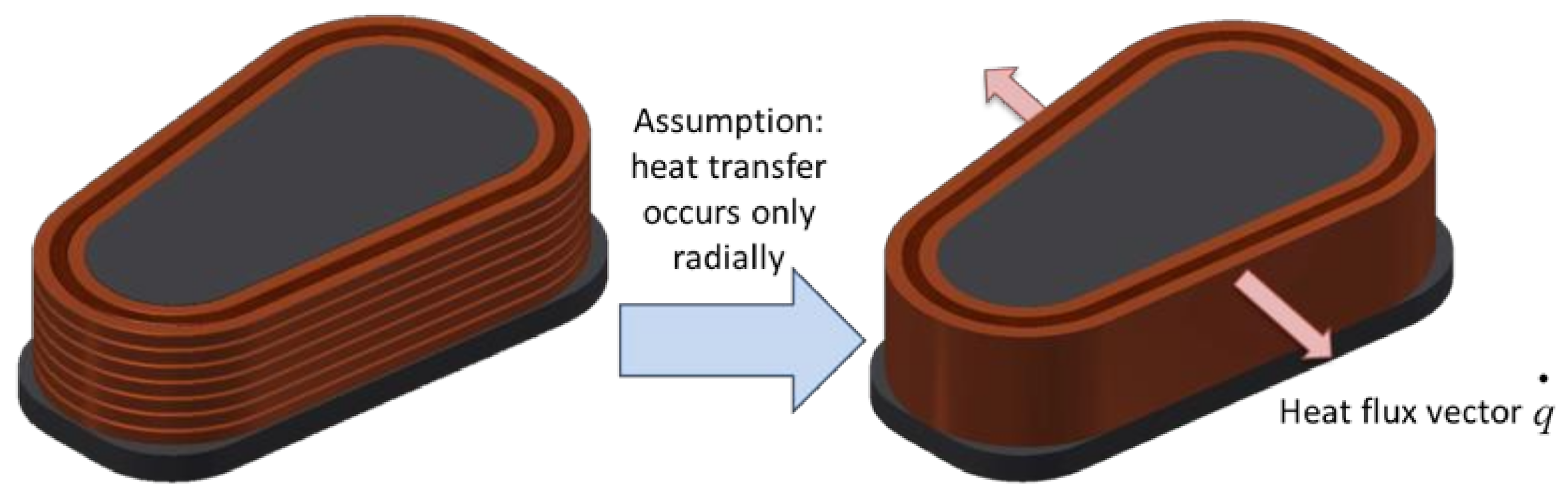
Energies 14 03619 g002
Figure 3. Simplification of the winding geometry. (Figure showing a cross section of the pole piece for better demonstration purposes).
Energies 14 03619 g003
Figure 4. Example of the comparison between (a) the traditional pole piece and (b) the new construction with heat sink integrated within the windings.
Energies 14 03619 g004
Figure 5. 3D CAD geometry and Boundary conditions for the single channel.
Energies 14 03619 g005
Figure 6. Mesh of the liquid channel in 3D CFD with details of the boundary layer.
Energies 14 03619 g006
Figure 7. Temperature profiles for (a) conventional concentrated windings with three layers, (b) a new construction with the heat sink mounted on the SMC iron, (c) new construction with the heat sink mounted between the 1st and 2nd layers. The results are for iron losses of 11 W and copper losses of 47 W.
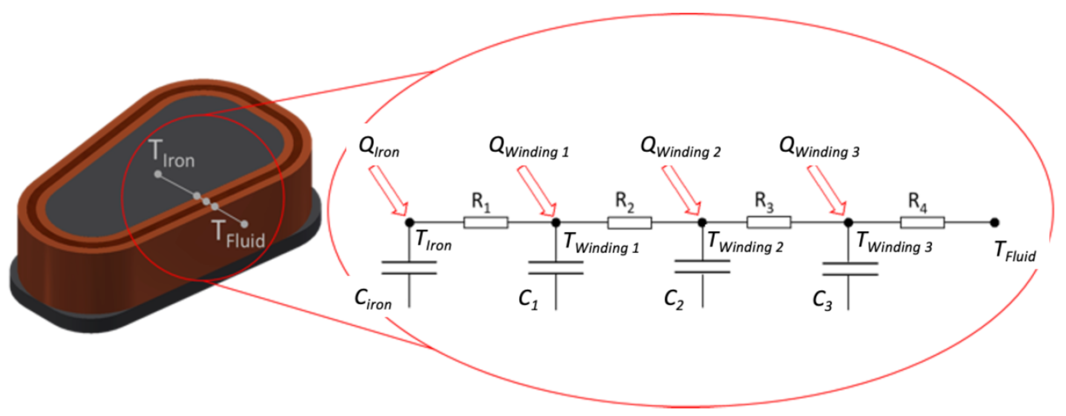
Energies 14 03619 g007
Figure 8. LP thermal model with nodes on each winding layer. (Insert) Thermal resistance network. The parameters Qiron and Qwinding are the heat loads supplied to the iron and the winding nodes, respectively. C1–C4 are the thermal capacity at each node. R1–R3 are the thermal resistances between the layers. R4 is the convective thermal resistance.
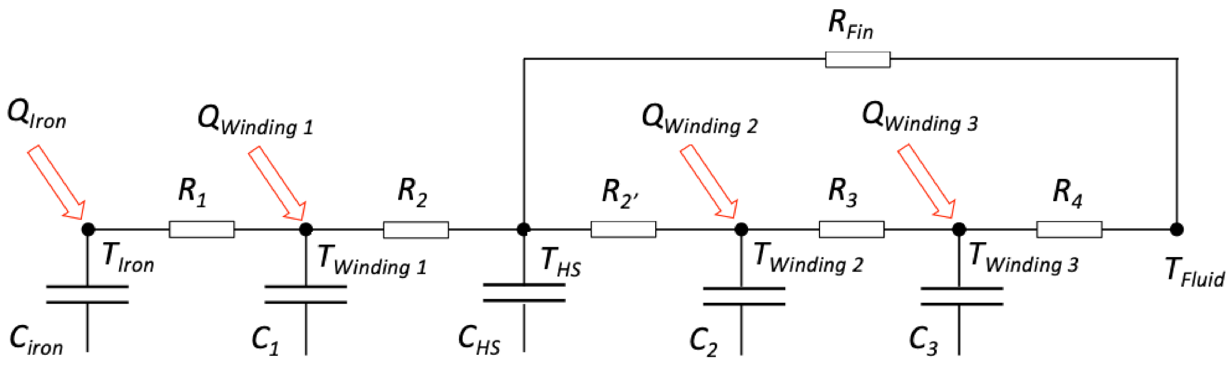
Energies 14 03619 g008
Figure 9. LP thermal model with a thermal node on each winding layer. The parameters Qiron and Qwinding are the heat loads supplied to the iron and windings, respectively. C1–C4 are the thermal capacity at each node. R1–R3 are inter-layer thermal resistances. R4 is the convective thermal resistance.
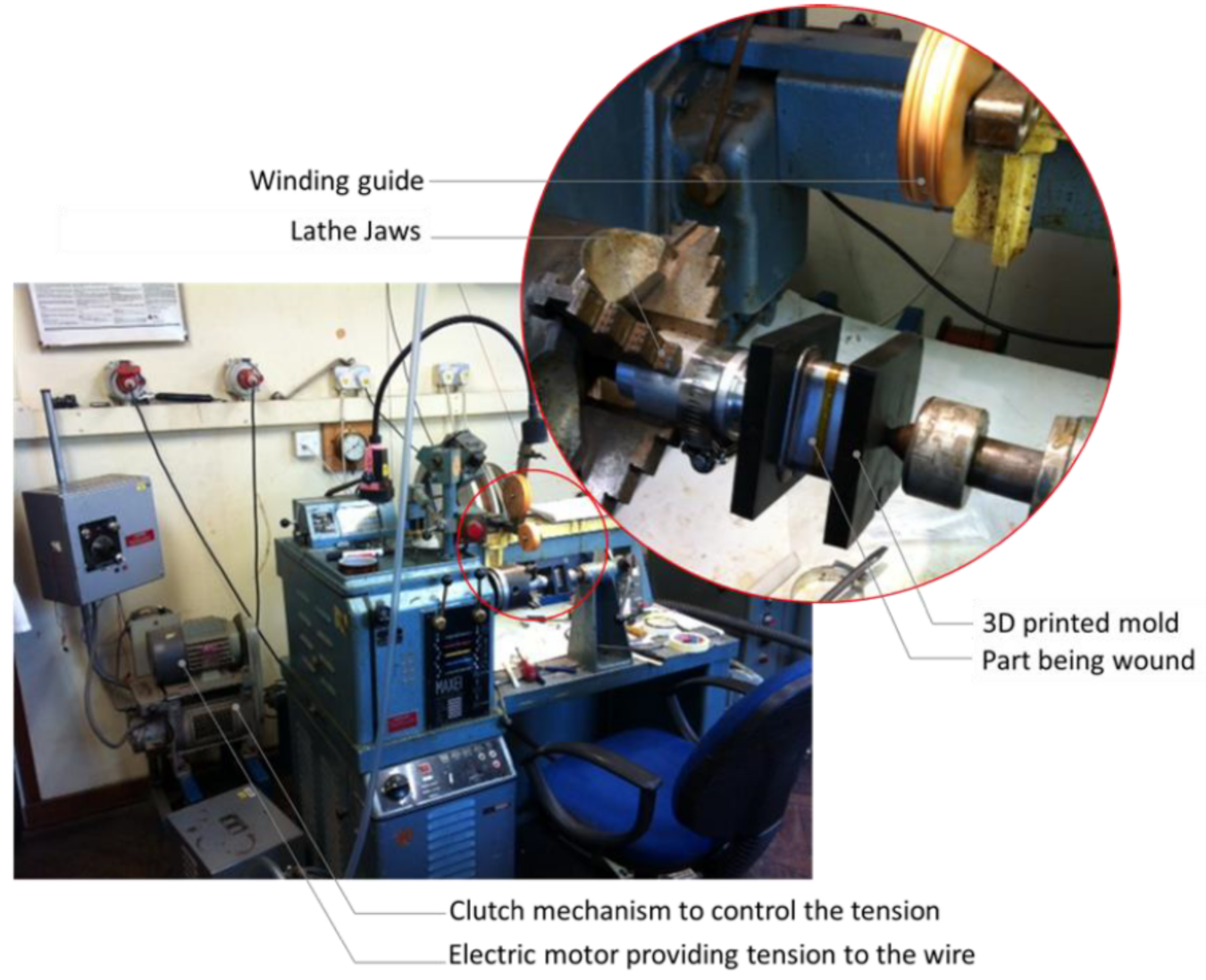
Energies 14 03619 g009
Figure 10. Details of the winding machine. (Insert) Details of the clamped pole.
Energies 14 03619 g010
Figure 11. CAD model for the heat sink.
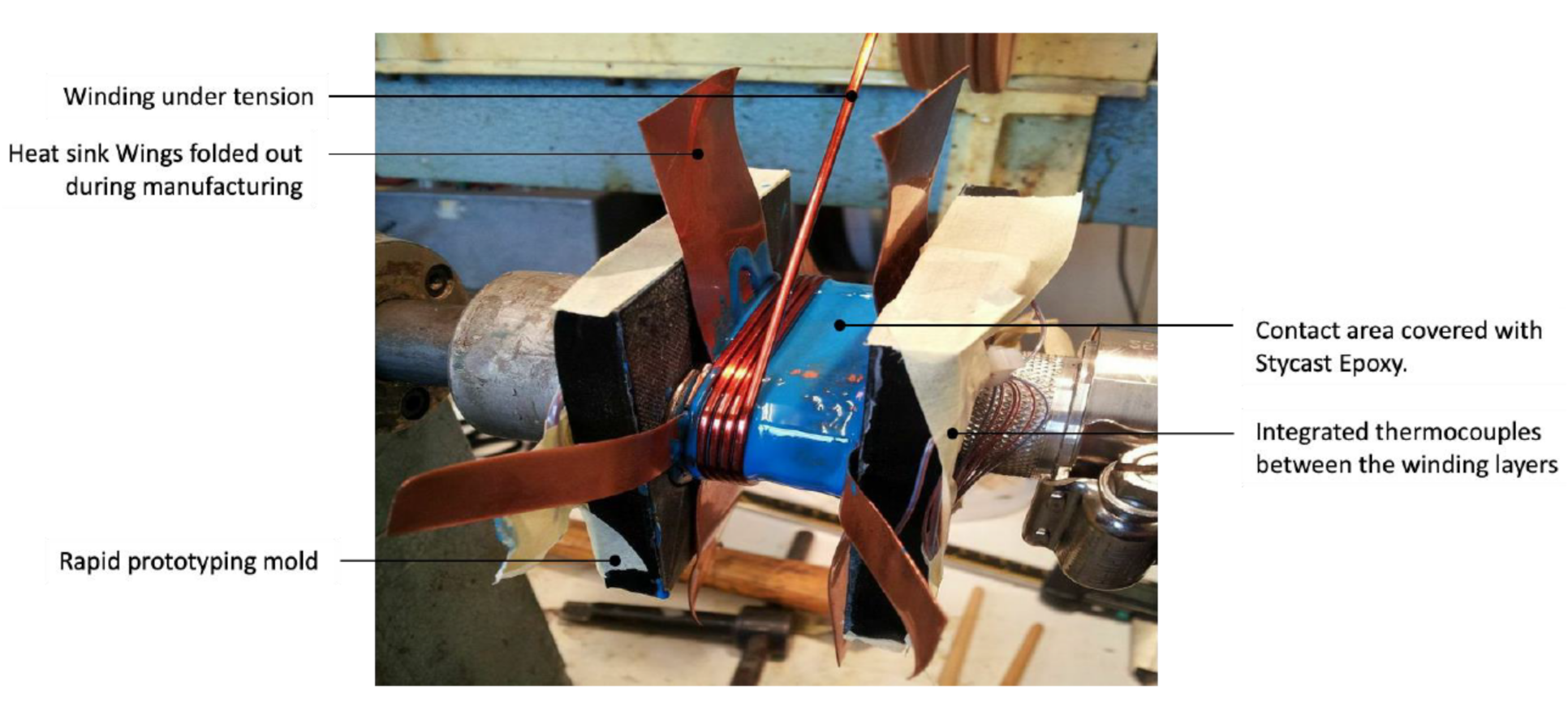
Energies 14 03619 g011
Figure 12. Details of the winding process with thermocouples mounted on the iron pole and between the winding layers.
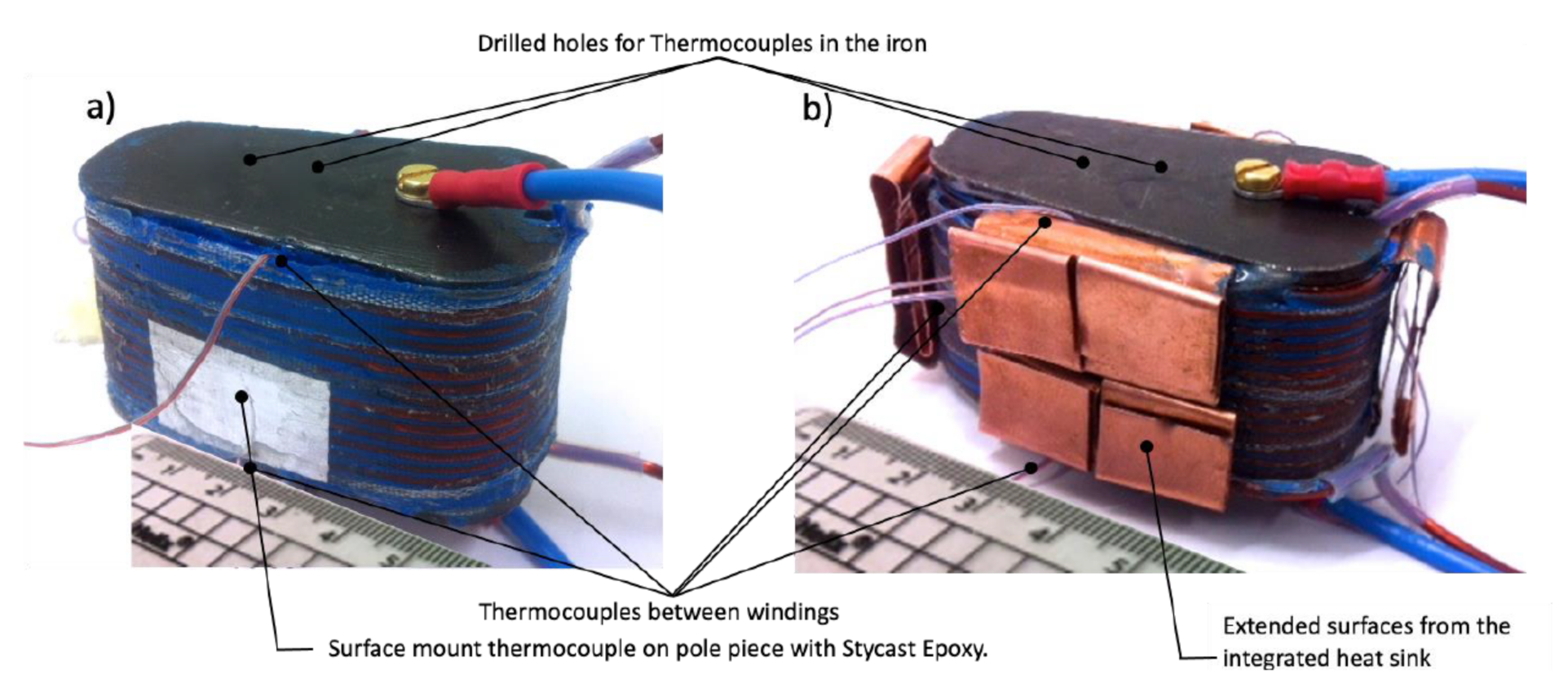
Energies 14 03619 g012
Figure 13. Prototypes of: (a) the traditional concentrated wound pole piece, and (b) the new construction.
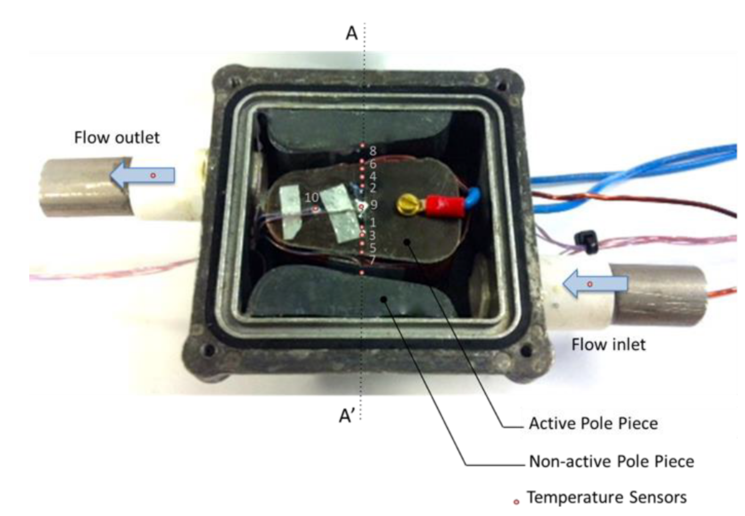
Energies 14 03619 g013
Figure 14. Test section recreating the flow geometry with the mounted instrumented pole piece. Line AA’ is used as a reference for the temperature profile.
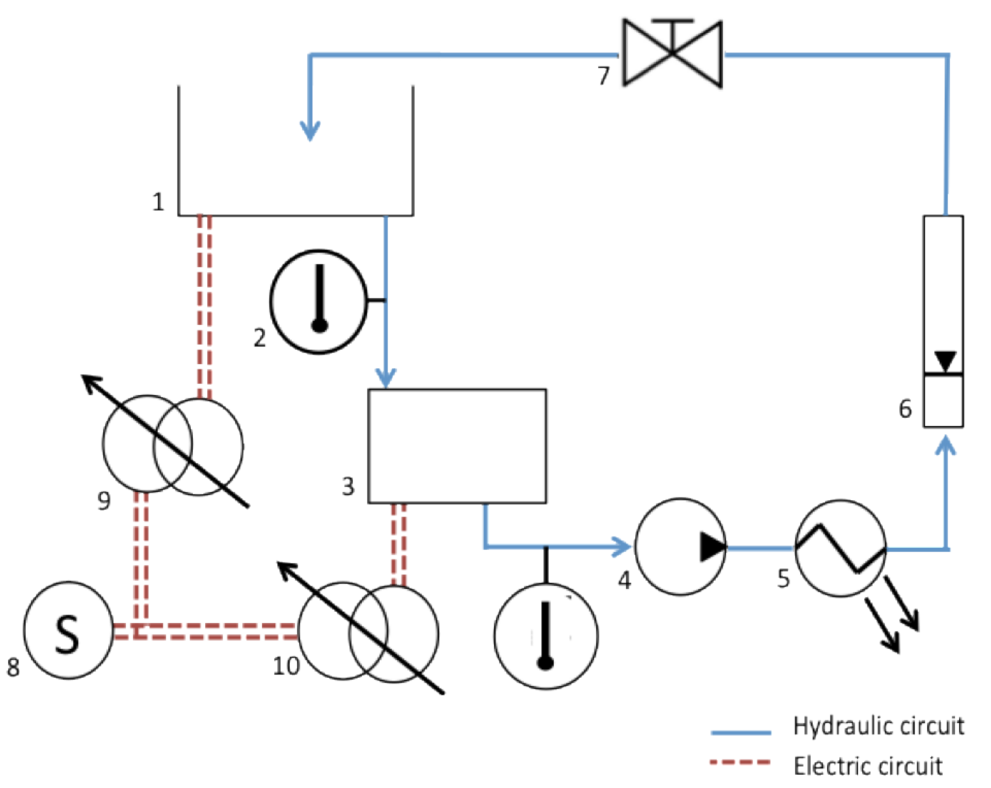
Energies 14 03619 g014
Figure 15. Test setup with (1) oil reservoir, (2) temperature sensors, (3) test box, (4) pump, (5) heat exchanger, (6) variable area flow meter, (7) globe valve, (8) AC power supply, (9) variable transformer powering fluid heater, (10) and the variable transformer powering pole piece heaters.
Energies 14 03619 g015
Figure 16. Thermal characterization of the model for a conventional pole piece and experiment conditions; also shown in Table 3, Test No. 1.
Energies 14 03619 g016
Figure 17. Comparison of the modelled and measured temperature profiles for a traditional pole piece under steady state conditions.
Energies 14 03619 g017
Figure 18. Comparison of the current density and coil temperature of a traditional coil and the new construction.
Energies 14 03619 g018
Table 1. Variation of coolant properties with temperature T, °C.
Opticool PropertiesEquationEquation No.
Density, ρ , kg/m3 ρ = 0.0052 T 2 + 0.2667 T + 786.76 (2)
Dynamic viscosity, μ , Pa.s μ = 0.0079 e 0.02 T (3)
Specific Heat Capacity, c , J/kgK c = 0.028 T 2 + 6.9105 T + 2044.9 (4)
Thermal conductivity, k , W/mK k = 1 e 7 T 2 8 e 5 T + 0.1376 (5)
Table 2. List of properties for SMC and copper windings.
Material PropertiesSMC IronCopper Windings
Density, ρ , kg/m375758800
Volume, m2.008 × 10−51.632 × 10⁻⁵
Specific Heat Capacity, c , J/kgK300400
Thermal conductivity, k , W/mK35300
Table 3. Specifications for Stycast Epoxy.
Material PropertiesValue
Epoxy NameStycast Epoxy
Dielectric Strength, kV/mm14.4
Thermal conductivity, W/mk1.25
Coefficient of thermal expansion, K−135 × 10−6
Density, kg/m32350–2450
Table 4. Transient calibration of the conventional windings.
Test No.Coolant Inlet Temperature °CFlow Rate m3/s (×10−6)SMC Heat Input WCoil Heat Input 1 W
123.961.623.182.6
223.961.610.946.0
339.580.023.080.2
438.678.310.236.7
1 Heat input for the windings at time = 0 s.
Table 5. Transient calibration of the new construction.
Test No.Coolant Inlet Temperature °CFlow rate m3/s (×10−6)SMC Heat Input WCoil Heat Input 1 W
123.961.621.86110.03
224.661.610.2072.80
324.041.622.06108.6
424.341.610.1671.16
1 Heat input for the windings at time = 0 s.
Table 6. Transient calibration of the conventional windings.
Test No.Coolant Inlet Temperature °CFlow Rate m3/s (×10−6)SMC Heat Input WCoil Heat Input 1 W
121.058.310.948.4
224.843.310.947.4
324.661.624.4114.9
424.843.324.4115.8
541.181.610.847.5
639.956.610.650.6
740.480.024.2114.6
839.958.324.3112.4
1 Heat input of the experiment running at steady state.
Table 7. Transient calibration of the new construction.
Test No.Coolant Inlet Temperature °CFlow Rate m3/s (×10−6)SMC Heat Input WCoil Heat Input 2 W
124.361.69.6848.88
223.941.610.1851.8
325.063.321.66108.4
425.143.322.1674.62
539.980.010.1853.15
639.656.610.2153.54
740.581.621.82112.44
841.660.022.2879.86
2 Heat input of the experiment running at steady state.
Table 8. Experimental fit for Rth for conventional windings.
DescriptionDesignateValue
Rth between pole piece and inner coil, K/WR10.12
Rth between inner and middle coils, K/WR20.18
Rth between middle and outer coils, K/WR30.45
SMC Specific heat capacity, J/kgK 300
Copper Specific heat capacity, J/kgK 400
Table 9. Experimental fit for Rth for conventional windings.
DescriptionDesignateValue
Rth between pole piece and inner coil, K/WR10.8
Rth between inner coil and heat sink, K/WR20.14
Rth between heat sink and middle coil, K/WR30.15
Rth between middle and outer coil, K/WR40.12
SMC Specific heat capacity, J/kgK 300
Copper Specific heat capacity, J/kgK 400
Publisher’s Note: MDPI stays neutral with regard to jurisdictional claims in published maps and institutional affiliations.

