Abstract
Conventional deadbeat control strategies for permanent magnet synchronous machines (PMSMs) are commonly developed reference frames, however, coupling dynamics affect the performance drive, and rotational transformations are required for the synthesis of the final voltage vector (VV). To improve robustness against parameter variations and to directly synthesize the reference voltage vector, in this paper a deadbeat predictive torque and flux control for a PMSM is presented. The proposed controller is developed in the stationary reference frame (). First, the reference VV is obtained from a predictive deadbeat controller. Then, the reference VV is applied to the power inverter by the combination of two voltage vectors. A duty cycle optimization is employed to calculate the required time for the application of each voltage vector. Experimental results based on an FPGA and a comparison of the conventional and the proposed deadbeat controller are presented to validate the proposed methodology.
1. Introduction
Model predictive control (MPC) has been one of the most popular control schemes for power electronics in the last years [1]. This popularity has increased with the advent of digital platforms with more computational power, leading MPC with the possibility to perform control of multiple-input multiple-output systems with physical constraints and nonlinear dynamics [2,3]. In the field of electrical drives, the application of MPC leads to a simple and intuitive control design. Furthermore, MPC has the advantage to perform the control without using rotational reference frame transformations or modulators, and MPC is commonly performed to control in a direct way the switching states of the power converter. Since the number of control actions in the power converter is limited, MPC becomes a constrained optimal control problem commonly known as finite set MPC (FS-MPC) [4].
Since FS-MPC is a discrete-time controller, the operation of FS-MPC is restricted to the switching transitions to the discrete-time instants of the sampling time, therefore, this parameter is an important factor that affects the performance of FS-MPC. When the sampling time is not properly selected, the performance of FS-MPC can hardly show better performance than conventional vector control schemes such as field oriented control (FOC) and direct torque control (DTC). In this way, the granularity of switching (ratio between the sampling frequency and the switching frequency) needs to be increased as much as possible [5].
A possible approach to increase the granularity of switching is to divide the sampling time into intervals to apply two or three switching states, i.e., voltages vectors (VVs), of the power converter during each control cycle [5]. This implies an increment of the granularity of switching by a factor of two or three. Some control schemes where the duty cycle of the applied VV is optimized can increase granularity of switching. For instance, in [6,7] the application of one active VV and one zero VV is performed; in [8,9], the application of two active VV and one zero VV is performed; in [10,11], the modulation is calculated based on a variable switching point.
Two approaches can be observed when duty cycle control is introduced in FS-MPC. In the first approach, the selection of the optimal VV is performed as in the conventional FS-MPC, and subsequently, the application time is computed [7,12,13]. This first approach may lead to sub-optimal results. In the second approach, the duty cycle computation is introduced into the control algorithm of FS-MPC and computed for each VV [6,14,15]. This second approach is computationally more expensive. An alternative to avoid the evaluation of all feasible VV and its corresponding duty cycles, is to use deadbeat control [16,17,18,19,20,21,22]. In theory, deadbeat control forces the torque and flux errors to zero in one sampling period and can be used to determine one single VV reference, which can be synthesized by a PWM modulator for application to the power inverter.
The application of the deadbeat predictive control for the PMSM has been widely researched. In [16], a deadbeat controller in the reference frame is proposed, deadbeat solution is used for the selection of the VV reference, and a cost function is evaluated for the final selection of the optimal VV. In [17], the combination of deadbeat control with sliding mode theory is presented, hence sliding mode control is used to control the speed of the machine and to deal with uncertainties. In [18], the deadbeat control with discrete space vector modulation (DSVM) is employed, here the reference voltage is selected based on deadbeat control, and the final application is performed on DSVM. In [19], a stator flux oriented deadbeat controller is proposed to avoid the rotor reference frame. In [20], a deadbeat controller with a perturbation observer is presented, the observer is used to compensate disturbances in the system. In [21], an analysis of some observers used in deadbeat control is presented. In [22], a deadbeat control with optimal switching sequence is presented. To apply the final VV selected based on the deadbeat solution, an optimal switching sequence is proposed.
The aforementioned deadbeat control strategies are developed in the rotor reference frame (), which can be considered as the conventional approach. One of the main problems of rotor frame, is that the machine model has coupling dynamics, which may affect the control performance by the relationship of the state variables. Furthermore, the final VV is applied to the PMSM by a modulation technique, therefore, a rotational transformation is necessary. Unlike conventional deadbeat control, this paper proposes a deadbeat predictive control for the torque and flux control of a PMSM in the stator reference frame (), which is the main contribution of this work. The main difference with previous approaches is the selection of the reference frame to formulate the predictive control. In the proposed approach, the current model of the PMSM is used to simplify the torque dynamic equation, and by the combination with the stator flux trajectory, the required reference voltage for application in the PMSM is obtained.
The proposed control scheme can be summarized in two steps. First, the torque and flux dynamics in the reference frame are used to formulate a predictive deadbeat control, which results in the components of required voltage of the reference voltage vector. Second, in contrast to the common formulation of deadbeat control where the final VV is applied based on the space vector modulation, the reference voltage vector is applied to the power inverter by using the method proposed by [22]. The combination of the proposed deadbeat control and the modulation introduced in [22], leads to better performance and stronger robustness against parameter variation than the conventional deadbeat controller. These assessments are validated by experimental results in a surface permanent magnet synchronous motor (PMSM) drive. The implementation of the proposed control scheme is performed in a field programmable gate array (FPGA), however, the proposed control algorithm can be implemented in a different digital platform.
The remainder of the paper is organized as follow. In Section 2, the theoretical background of the proposed methodology is presented; in Section 3, the main contribution of the presented paper is presented; in Section 4 the experimental results are presented; in Section 5 the discussion of the results is presented; in Section 6 the conclusions of the paper are presented.
2. Theoretical Background
PMSM Mathematical Model
The torque and flux control of the PMSM is commonly performed in the stationary reference frame , therefore, the mathematical model of a surface PMSM can be described in the stationary reference frame as [23]:
where:
in (1)–(2), , and are the orthogonal components of voltage, current and flux in - reference frame, respectively; is the stator inductance; is the stator resistance; is the electrical rotor position; is the electrical speed; p is the number of pole pairs; and is the flux linkage of the permanent magnets of the rotor. Predictive control is performed in discrete time, therefore, the continuous time PMSM model is used for the prediction of the machine variables. A discretization of the mathematical model of the PMSM can be performed based on the Euler forward differentiation method as in [24].
3. Proposed Deadbeat Predictive Control
As discussed in the introduction, the conventional deadbeat control is designed in the rotor reference frame. In this approach, the voltage required to force the torque and flux response to their corresponded references in one sampling period is determined. Then, the final voltages need to be transformed to the stator reference frame to be applied through the space vector modulation. Although the deadbeat control reference frame has been widely investigated [16,17,18,20,21,22], the application of the final voltage has to be performed in the stator reference frame. Therefore, the selection of stator reference frame can be seen as a more natural reference frame to design the deadbeat control of the PMSM. This results in a controller where the dynamics are decoupled, and rotational transformations are no longer required. Since coupling dynamics are not presented, in the proposed deadbeat control, the robustness against parameter variation is stronger than the conventional deadbeat control.
The proposed deadbeat controller is designed in the stator reference frame by using the model of the PMSM. Thus, rotational transformations are avoided, and the final VV can be directly synthesized by the PWM modulator. In this paper, the application of the final VV is performed based on the idea introduced in [22,25], where the optimal times of the switching states of the power converter are calculated. In summary, the proposed deadbeat controller is used to determine the reference VV, and then the final reference VV is synthesized based on the optimal times determined as proposed in [22,25].
3.1. Stator Fixed Deadbeat Predictive Control
In order to perform deadbeat control, torque dynamics are considered. However, when using (1c) to determine the torque derivative, the flux and current derivatives are presented in the resulting equation. To simplify the expression that describes torque dynamics, the stator flux equations can be written as
By using (3) and (1c), the torque of the PMSM can be determined as
and torque dynamics can be obtained from (4) as follows
where
The sampling time of the controller can be considered fast enough to give sufficient accuracy in the discrete approximation of (7), and the speed can be considered constant along one sampling period. Hence, the discrete time form of (7) in the instant time can be obtained as
It can be considered that torque of the PMSM varies linearly from one sampling time to the next sampling time. Then, the change in the torque can be expressed as
According to deadbeat control principle, the developed torque reaches the reference in the next sampling period. Therefore, , and can be rewritten as
and (8) can be rewritten in the form of (11). It can be seen than the rate of change in the torque of the PMSM is based on a linear relationship for the voltages and the commanded change in the torque of the PMSM. This linear relation can be expressed in terms of the stator voltages as shown in (12).
where
The solution of (12) would yield multiple possible stator voltages, therefore, a deadbeat torque control can be obtained. However, some restrictions must be considered in the selection of the possible stator voltages. In principle, the stator voltages are limited in the practical, and can no be selected higher than the available DC-bus voltage. Moreover, these voltages have a direct effect in the stator flux of the machine, which should be considered in the control design. Assuming that the stator flux is following a circular trajectory with constant magnitude according to the stator flux reference, the stator flux reference can be written as a combination of its components as
The stator flux given by (14) can be further expanded by using the discrete approximation of (2), (12), and by neglecting the voltage drop in the resistance results in (15).
The reference stator flux can be considered constant below the flux weakening region. Since flux weakening operation is not considered in this paper, , and (15) can be given by
By solving (16) for the voltage, a quadratic function is obtained. The solution for results in
where
The application of (12) and (17) will result in the required voltages components of the reference VV, i.e., and . This reference VV will be applied to reach the torque and flux reference in the next sampling period. It can be seen from (17) that two solutions are obtained, and in combination with (12), results in two possible reference VVs for application in the power inverter. The selection of the appropriate final VV should be done based on the magnitude of the resulting reference VV, therefore, the reference VV with small magnitude should be selected as the final reference VV for application in the power inverter.
3.2. Duty Cycle Calculation
In conventional deadbeat control, the reference stator voltage is synthesized based on the space vector modulation (SVM). However, according to [22,25] the duty cycles of the switching states for the application of the reference vector are not optimal. Nevertheless, it is possible to define a cost function to calculate the optimal duty cycles of the switching states.
Similarly to the SVM, the space VVs of the power inverter can divide the plane as shown in Figure 1. The sector m where the reference voltage vector lies can be used to select the two nearest adjacent VVs to synthesize the final VV. The angle of the reference stator voltage vector can be calculated as
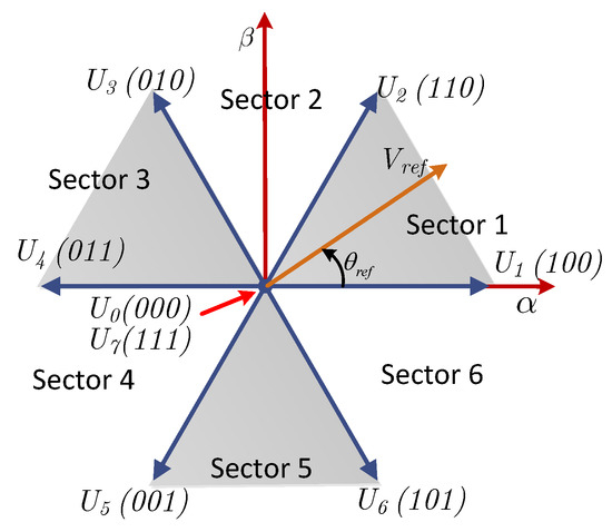
Figure 1.
Representation of the voltage vector of the power inverter in the plane.
The reference voltage is then applied by the combination of the VV , and a zero VV in their respective times , , and . In this way, the components of the reference voltage synthesized by the PWM principle can be given as
where , are the components of the synthesized reference voltage; are the components of the VVs , and zero VV, respectively; are the components of the VVs , and zero VV, respectively; and and are the application times of the VVs , , and zero VV, respectively. The duty cycles can be rewritten as the ratio between the sampling time and the application time of each VV, therefore, the components of the synthesized reference voltage are given by
where and are the duration ratio of the VVs , and zero VV, respectively. The optimal duration ration of and can be obtained from the formulation of the following cost function [25]:
The optimal duration ratio satisfies the following expressions:
The solution of (22), based on (20) and (21) leads to the optimal duration ratios given as
where
According to (23), the duration ratio of the VVs to synthesize the reference voltage is obtained. The final application of the optimal times is performed in a similar way to the SVM, and to minimize the switching losses the zero VV is used at the beginning, in the middle, and at the end of the control cycle.
3.3. Overall Control Algorithm of the Proposed Deadbeat Control
A simplified representation of the proposed controller is shown in Figure 2. The following steps are required to implement the proposed control algorithm:
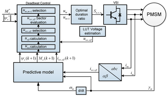
Figure 2.
Simplified representation of the proposed control scheme.
- Apply the previously calculated reference voltage using the calculated duty cycles.
- Sample the position and currents of the PMSM, and transform the currents to the reference frame.
- Predict the machine variables at the sampling time (k + 1) by using the predictive model and the applied reference voltage.
- Calculate based on (17).
- Calculate based on (12).
- Discard the VV with higher amplitude from the solutions of (12) and (17).
- Calculate the angle of the reference voltage vector using (18).
- Select the two nearest adjacent VV to the reference voltage vector.
- Calculate the optimal duration ratios of the synthesized reference voltage vector based on (23).
- Calculate the duty cycles similar to the SVM for the next control cycle.
- Repeat 1 in the next sampling time
4. Experimental Results
A simplified diagram of the experimental setup is shown in Figure 3. The experimental validation is carried out in a surface PMSM connected to a SEMIKRON two level voltage source inverter. The nominal parameters of the machine used are shown in Table 1. The control is implemented in an FPGA development board with a Cyclone IV EP4CE115. Currents are measured using the LTS-25np hall sensor, and the position is obtained from a quadrature encoder of 2024 ppr. The voltage of the DC bus is set at 300 VDC. The sampling frequency of the evaluated control schemes is set at 18 kHz. In the experimental results, the currents are directly measured by a current probe, and the waveforms of the remaining variables are shown in the scope through the digital analog converter (DAC) of a custom board. In order to perform a comparison, the conventional deadbeat controller is implemented and compared with the proposed deadbeat controller. The control algorithms are implemented using VHDL code with an architecture based on 32 bits fixed point (1 bit for the sign, 15 bits for the real part, and 16 bits for the decimal part).
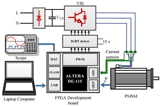
Figure 3.
Simplified block diagram of the experimental setup.

Table 1.
PMSM Parameters.
In order to evaluate the torque response of the system, an experimental evaluation with rated torque is performed for the conventional and the proposed deadbeat control, respectively. The experimental results under steady state are shown if Figure 4 and Figure 5 for the conventional and the proposed deadbeat control, respectively. In order to evaluate the torque ripple and flux ripple , the standard deviation is calculated as
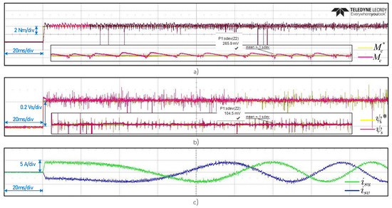
Figure 4.
Steady state experimental results of the conventional deadbeat control. (a) Electromagnetic torque. (b) Stator flux. (c) Stator currents.
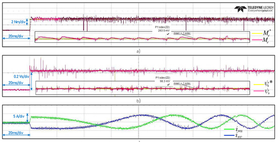
Figure 5.
Steady state experimental results of the proposed deadbeat control. (a) Electromagnetic torque. (b) Stator flux. (c) Stator currents.
In this experimental evaluation, the torque reference is set from 0 to 4 Nm; and the flux reference is set to 0.22 Vs. The reference flux has been calculated according to the maximum torque value. The experimental results shown a fast dynamic torque and flux response, which successfully follows the torque and flux reference. In Figure 4a and Figure 5a, the torque response reach the reference value in approximately 2 ms for both controllers. According to the scope measurements, the torque ripple of the conventional deadbeat control is equal to 0.265 Nm, and for the proposed deadbeat control is 0.254 Nm. In a similar way, in Figure 4b and Figure 5b the flux response reach the reference value in less than 1 ms. It can be observed some noise introduced in the flux measurement, this is attributed to the low resolution of the DAC used. In the flux results, a flux ripple of 0.104 Vs is obtained in the conventional deadbeat control, and a flux ripple of 0.098 Vs is obtained for the proposed deadbeat control. A detailed response of the machine variables is shown inside Figure 4a,b and Figure 5a,b, where a zoom is shown in the bottom of each figure. It can be noted that the torque and flux of the machine follow the reference successfully.
In order to evaluate the flux and torque ripple in steady state, similar experiments are performed for different values of torque with constant flux. These results are summarized in Figure 6. The results show that the torque and flux ripple of the conventional deadbeat control is larger than the torque and flux ripple of the proposed deadbeat control.
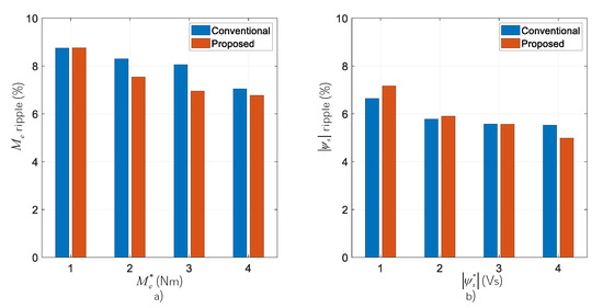
Figure 6.
Steady state experimental evaluation of the conventional and the proposed deadbeat control. (a) Electromagnetic torque ripple percentage. (b) Stator flux ripple percentage.
The evaluation of the dynamic response of the control schemes is shown in Figure 7. In this evaluation, the torque reference is initially set to −4 Nm, then, a positive torque reference of 4 Nm is commanded to the PMSM. It can be observed in Figure 7a–c that the dynamic torque response of the PMSM is similar for both deadbeat control schemes. However, the torque ripple in the proposed deadbeat control is lower than conventional deadbeat control. In a similar way, in Figure 7b–d the flux response during dynamic evaluation shows a similar response for the conventional and the proposed deadbeat control.
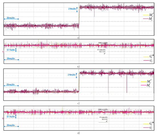
Figure 7.
Dynamic state experimental results. (a) Electromagnetic torque conventional deadbeat control. (b) Stator flux conventional deadbeat control. (c) Electromagnetic torque proposed deadbeat control. (d) Stator flux proposed deadbeat control.
In order to evaluate the robustness against parameter variations of the proposed control scheme, an experimental evaluation where the stator resistance and stator inductance are varied is presented. This evaluation is performed for a 50% and a 80% variation of nominal parameters. The experimental evaluation of the robustness against parameter variation is performed under constant torque demand. In this test, the torque reference is set to 4 Nm and the flux reference is set to 0.2 Vs. The variation of the PMSM parameter is externally applied at the startup of the machine.
The experimental results when and are varied 50% from the nominal values are shown in Figure 8. As shown in Figure 8a,b, the torque response of the conventional and the proposed deadbeat control are similar, and both controllers are capable of following the reference successfully. However, the torque ripple of both controllers increases to 0.325 Nm and to 0.311 Nm for the conventional and the proposed deadbeat control, respectively. On the other hand, the flux of the PMSM is more affected in both controllers when the parameters vary. In this results, an increment to 0.148 Vs and to 0.142 Vs flux ripple is obtained for the conventional and the proposed deadbeat control, respectively.
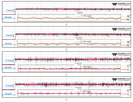
Figure 8.
Experimental results under parameter variation of 50% from nominal parameters. (a) Electromagnetic torque conventional deadbeat control. (b) Stator flux conventional deadbeat control. (c) Electromagnetic torque proposed deadbeat control. (d) Stator flux proposed deadbeat control.
Finally, the experimental results when the parameters of the PMSM are varied 80% from nominal values are shown in Figure 9. In this evaluation, the torque response of the conventional and the proposed deadbeat controller follows the reference successfully as shown in Figure 9a,b, however, the torque ripple is increased to 0.320 Nm and to 0.318 Nm for the conventional and the proposed deadbeat control, respectively. In this evaluation test, the flux of the PMSM is considerable affected by the parameter variation. In this test, the flux ripple of the conventional deadbeat control is equal to 0.621 Vs, and for the proposed deadbeat control is equal to 0.607 Vs. It can be seen that the proposed control is less affected by parameter variations.
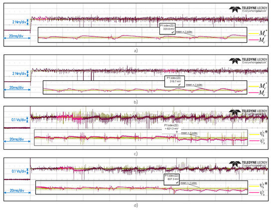
Figure 9.
Experimental results under parameter variation of 80% from nominal parameters. (a) Electromagnetic torque conventional deadbeat control. (b) Stator flux conventional deadbeat control. (c) Electromagnetic torque proposed deadbeat control. (d) Stator flux proposed deadbeat control.
5. Discussion of the Results
Experimental results have shown that the proposed deadbeat control scheme is capable of tracking the reference torque and flux effectively in the steady and dynamic state. Based on the experimental results, and in comparison with the conventional deadbeat torque and flux control, it can be concluded that similar performance is obtained if a deadbeat control is designed for stator reference frame. However, when the parameters variation are introduced in the PMSM, the proposed deadbeat control has stronger robustness than the conventional deadbeat controller. This can be associated with the natural dynamics of the PMSM. As it is known, PMSM rotor frame equations present coupled dynamics. In contrast, stator frame equations give strong robustness because stator flux does not have coupled dynamics.
The experimental results have shown that several steps are required to reach the torque and flux reference under the proposed predictive deadbeat control, mainly because of limitations in the DC bus voltage. Although theoretically, in deadbeat control, the commanded reference is reached in one sampling time, this requires the application of control actions with large amplitude. However, this is not possible in real systems, in the case of the PMSM, the voltage and current need to be limited to nominal values, which affect dynamic response, but keep the machine in safe operation. In the proposed predictive deadbeat control, the voltage is limited to the lineal region of the power inverter.
Since the proposed deadbeat control is highly dependent on the PMSM parameters, and the flux and torque of the PMSM are estimated based on a stator flux observer designed with the current model (by using the predictive model); the application of robust observers may improve the control performance by the compensation of the parameter variation.
In comparison with conventional FS-MPC, the proposed deadbeat control has the advantage of the direct calculation of the reference voltage for application in the power inverter, therefore, the enumeration problem is avoided. Although the solution of the reference voltage vector is based on the calculation of a quadratic Equation (17), this does not represent a heavy computation burden. In the case of this paper, the solution of this equation is performed based on the coordinate rotation digital computer algorithm, which simplifies the solution of (17) to simple shifts and registers.
Finally, the experimental results suggest that the proposed deadbeat control can be used as a possible solution for high-performance drives. Furthermore, future research can be oriented to the design of robust observers to improve the control performance.
6. Conclusions
In this paper, a stator fixed deadbeat predictive torque and flux control for a PMSM drive is proposed. Compared to conventional approaches frame, the proposed predictive deadbeat control is developed in the stator reference frame, resulting in non-coupling dynamics, and no need for rotational transformations. The final reference voltage obtained from the proposed deadbeat predictive control is applied to the power inverter through the optimal calculation of the switching times.
An experimental comparison of the conventional deadbeat control and the proposed deadbeat control is performed to validate the proposed methodology. The experimental results show a fast torque and flux response in steady and dynamic operation, and a successful track of the commanded torque and flux reference by the electric drive. Compared to the conventional deadbeat control, the proposed predictive deadbeat control scheme presents better results in steady state, with a lower torque ripple.
An evaluation of robustness against parameter variation is performed. The experimental results shown that the proposed deadbeat predictive control is less sensitive to parameter variation than conventional deadbeat control, and successfully follows the torque and flux references despite parameter variations. Based on the results, the proposed control scheme can be considered as a possible solution for high-performance drives.
Author Contributions
The present work has been developed by the authors in charge of their expertise and capability: O.S.H. for investigation and experimental validation; J.S.C.-R., J.P.O.O., and C.C.C. for analysis, and writing. All authors have read and agreed to the published version of the manuscript.
Funding
This work was supported by the program for teacher professional development (PRODEP).
Institutional Review Board Statement
Not applicable.
Informed Consent Statement
Not applicable.
Conflicts of Interest
The authors declare no conflict of interest.
References
- Cortes, P.; Kazmierkowski, M.P.; Kennel, R.M.; Quevedo, D.E.; Rodriguez, J. Predictive Control in Power Electronics and Drives. IEEE Trans. Ind. Electron. 2008, 55, 4312–4324. [Google Scholar] [CrossRef]
- Camacho, E.F.; Bordons, C. Model Predictive Control, 3rd ed.; Springer: New York, NY, USA, 1999. [Google Scholar]
- Maciejowski, J.M. Predictive Control with Constraints, 1st ed.; Prentice-Hall: Hoboken, NJ, USA, 2002. [Google Scholar]
- Wang, F.; Li, S.; Mei, X.; Xie, W.; Rodríguez, J.; Kennel, R.M. Model-Based Predictive Direct Control Strategies for Electrical Drives: An Experimental Evaluation of PTC and PCC Methods. IEEE Trans. Ind. Inform. 2015, 11, 671–681. [Google Scholar] [CrossRef]
- Karamanakos, P.; Geyer, T. Guidelines for the Design of Finite Control Set Model Predictive Controllers. IEEE Trans. Power Electron. 2020, 35, 7434–7450. [Google Scholar] [CrossRef]
- Sandre Hernandez, O.; RangelMagdaleno, J.; Morales Caporal, R. Modified model predictive torque control for a PMSM-drive with torque ripple minimisation. IET Power Electron. 2019, 12, 1033–1042. [Google Scholar] [CrossRef]
- Zhang, Y.; Yang, H. Model Predictive Torque Control of Induction Motor Drives with Optimal Duty Cycle Control. IEEE Trans. Power Electron. 2014, 29, 6593–6603. [Google Scholar] [CrossRef]
- Zhang, Y.; Huang, L.; Xu, D.; Liu, J.; Jin, J. Performance evaluation of two-vector-based model predictive current control of PMSM drives. Chin. J. Electr. Eng. 2018, 4, 65–81. [Google Scholar]
- Zhang, X.; Hou, B. Double Vectors Model Predictive Torque Control without Weighting Factor Based on Voltage Tracking Error. IEEE Trans. Power Electron. 2018, 33, 2368–2380. [Google Scholar] [CrossRef]
- Karamanakos, P.; Stolze, P.; Kennel, R.M.; Manias, S.; du Toit Mouton, H. Variable Switching Point Predictive Torque Control of Induction Machines. IEEE J. Emerg. Sel. Top. Power Electron. 2014, 2, 285–295. [Google Scholar] [CrossRef]
- Wendel, S.; Karamanakos, P.; Dietz, A.; Kennel, R. Operating Point Dependent Variable Switching Point Predictive Current Control for PMSM Drives. In Proceedings of the 2019 IEEE International Symposium on Predictive Control of Electrical Drives and Power Electronics (PRECEDE), Quanzhou, China, 31 May–2 June 2019; pp. 1–6. [Google Scholar]
- Davari, S.A.; Khaburi, D.A.; Kennel, R. An Improved FCS–MPC Algorithm for an Induction Motor with an Imposed Optimized Weighting Factor. IEEE Trans. Power Electron. 2012, 27, 1540–1551. [Google Scholar] [CrossRef]
- Zhang, Y.; Yang, H. Model-Predictive Flux Control of Induction Motor Drives with Switching Instant Optimization. IEEE Trans. Energy Convers. 2015, 30, 1113–1122. [Google Scholar] [CrossRef]
- Bao, G.; Qi, W.; He, T. Direct Torque Control of PMSM with Modified Finite Set Model Predictive Control. Energies 2020, 13, 234. [Google Scholar] [CrossRef]
- Yuan, Q.; Ma, T.; Zhao, R.; Yang, Y. A General Double Vector-Based Model Predictive Current Control for the Dual Three-Phase Motors. Electronics 2020, 9, 2000. [Google Scholar] [CrossRef]
- Xie, W.; Wang, X.; Wang, F.; Xu, W.; Kennel, R.M.; Gerling, D.; Lorenz, R.D. Finite-Control-Set Model Predictive Torque Control with a Deadbeat Solution for PMSM Drives. IEEE Trans. Ind. Electron. 2015, 62, 5402–5410. [Google Scholar] [CrossRef]
- Jiang, Y.; Xu, W.; Mu, C.; Liu, Y. Improved Deadbeat Predictive Current Control Combined Sliding Mode Strategy for PMSM Drive System. IEEE Trans. Veh. Technol. 2018, 67, 251–263. [Google Scholar] [CrossRef]
- Wang, Y.; Wang, X.; Xie, W.; Wang, F.; Dou, M.; Kennel, R.M.; Lorenz, R.D.; Gerling, D. Deadbeat Model-Predictive Torque Control with Discrete Space-Vector Modulation for PMSM Drives. IEEE Trans. Ind. Electron. 2017, 64, 3537–3547. [Google Scholar] [CrossRef]
- Lin, X.; Huang, W.; Jiang, W.; Zhao, Y.; Zhu, S. Deadbeat Direct Torque and Flux Control for Permanent Magnet Synchronous Motor Based on Stator Flux Oriented. IEEE Trans. Power Electron. 2020, 35, 5078–5092. [Google Scholar] [CrossRef]
- Zhang, X.; Hou, B.; Mei, Y. Deadbeat Predictive Current Control of Permanent-Magnet Synchronous Motors with Stator Current and Disturbance Observer. IEEE Trans. Power Electron. 2017, 32, 3818–3834. [Google Scholar] [CrossRef]
- Lee, J. Stability Analysis of Deadbeat-Direct Torque and Flux Control for Permanent Magnet Synchronous Motor Drives with Respect to Parameter Variations. Energies 2018, 11, 2027. [Google Scholar] [CrossRef]
- Kang, S.; Soh, J.; Kim, R. Symmetrical Three-Vector-Based Model Predictive Control with Deadbeat Solution for IPMSM in Rotating Reference Frame. IEEE Trans. Ind. Electron. 2020, 67, 159–168. [Google Scholar] [CrossRef]
- Krishnan, R. Permanent Magnet Synchronous and Brushless DC Motor Drives, 1st ed.; CRC Press: London, UK, 2017. [Google Scholar]
- Sandre-Hernandez, O.; Rangel-Magdaleno, J.; Morales-Caporal, R. A Comparison on Finite-Set Model Predictive Torque Control Schemes for PMSMs. IEEE Trans. Power Electron. 2018, 33, 8838–8847. [Google Scholar] [CrossRef]
- Wang, Q.; Yu, H.; Li, C.; Lang, X.; Yeoh, S.S.; Yang, T.; Rivera, M.; Bozhko, S.; Wheeler, P. A Low-Complexity Optimal Switching Time-Modulated Model-Predictive Control for PMSM with Three-Level NPC Converter. IEEE Trans. Transp. Electrif. 2020, 6, 1188–1198. [Google Scholar] [CrossRef]


Publisher’s Note: MDPI stays neutral with regard to jurisdictional claims in published maps and institutional affiliations. |
© 2021 by the authors. Licensee MDPI, Basel, Switzerland. This article is an open access article distributed under the terms and conditions of the Creative Commons Attribution (CC BY) license (https://creativecommons.org/licenses/by/4.0/).