Article

WAMS-Supported Power Mismatch Optimization for Secure Intentional Islanding

Faculty of Electrical Engineering, University of Ljubljana, 1000 Ljubljana, Slovenia
*
Author to whom correspondence should be addressed.
Energies 2021, 14(10), 2790; https://doi.org/10.3390/en14102790
Submission received: 15 April 2021 / Revised: 7 May 2021 / Accepted: 9 May 2021 / Published: 12 May 2021

Abstract

:
It is expected that a coordinated operation of several system integrity protection schemes will become a necessity in the future. This research represents an innovative strategy for coordinating under-frequency load shedding and intentional controlled islanding schemes for improving electric power system stability and resilience. In the great majority of real-world cases, both approaches follow conventional tactics, i.e., disconnecting a fixed number of feeders at predefined frequency thresholds and isolating a predefined area of a power system regardless of the actual conditions. Under the newly arisen network conditions in which weather-dependent distributed energy sources introduce a significant level of intermittency, conventional approaches need to be upgraded in order to retain a high level of power system operation security. In this paper, a mixed-integer linear programming approach is used to adjust the island size, including/excluding additional substations according to the available amount of generation in the region. The fine-tuning of the power rebalancing is achieved by potentially blocking selected load shedding stages. This minimizes the power imbalance of the newly formed islands, which helps to reduce the number of partial or even total blackouts and also accelerates the power system’s restoration process. The optimization approach was tested on a generic IEEE 39-bus network and shows promising results along with the capability of coping with real-world applications using wide-area monitoring systems as a source of real-time measurements. The results also indicated the importance of appropriate load modelling since both voltage and frequency dependence are recognized to have a significant effect on intentional controlled islanding.

1. Introduction

By definition, an electric power system (EPS)’s operation is deemed stable when all state variables (such as frequency, rate of change of frequency, voltage magnitudes, etc.) are within the permissible bounds and steady. When these conditions are not met, corrective actions need to be taken to avoid cascade tripping that may result in an unsupervised EPS separation or even a widespread blackout. These actions are referred to as system integrity protection schemes (SIPSs) whose task is to eliminate the risk of severe socio-economic damage caused by a blackout. The most commonly applied SIPSs are under-frequency and under-voltage load shedding (UFLS and UVLS, respectively) schemes [1] that often suffice for EPS stabilization [2]. However, this is not always the case [3,4].
To set up an additional protection barrier, a so-called intentional controlled islanding (ICI) scheme has been presented and researched recently [5,6,7,8,9]. ICI is a corrective measure scheduled for activation only when the remaining set of SIPSs is fully exhausted and not capable of stabilizing the system on its own. Its aim is to split the EPS into multiple stable and self-sustainable islands. To this end, it is of the utmost importance to ensure a sufficient level of active power balance within the island.
In this respect, it has been shown in the existing literature that coordination between ICI and other SIPSs, such as UFLS, needs to be researched [10]. Namely, it turned out that an UFLS scheme operating by means of frequency and rate-of-change-of-frequency (RoCoF) relay tripping is not always able to avoid frequency instability.
Constructional limitations in steam and gas turbines dictate avoidance from operating below 47.5 Hz (in 50 Hz systems) and 57.0 Hz (in 60 Hz systems) [11]. The reason is that the life expectancy of the turbines below these thresholds starts to significantly decrease and they are exposed to potential physical damage due to the excitation of the resonant frequencies of the turbine blades. To avoid such undesired consequences, power plants using steam and gas technology are equipped with under-frequency protection. However, the malfunction or poor parameterization of under-frequency protection can also be the cause of a blackout. A good example to support this claim is the 2003 Italy blackout [4].
The most commonly used criterion by an ICI scheme for the determination of island boundaries is the minimization of a power exchange with the rest of the system. This approach is based on the real-time monitoring of the transmission line power flows [7,12]. In fact, this is very similar to minimizing the active power imbalance within the island ([8,13]) while other approaches focus on synchronous generator angle instability [12]. In several cases, the coherence criterion was used to determine groups of synchronous generators that do not experience significant electromechanical oscillations against each other [14,15,16] (i.e., finding coherent groups of generators and include them in the same island). The two most evident drawbacks of the latter approach are (i) the dependence of calculation results on the pre-incident equilibrium point and (ii) not considering topology changes. As an improvement of this approach, spectral clustering is often used in combination with the advances of the slow coherency approach [9]. Nevertheless, some of the drawbacks remain, such as ignoring the possibility of transient stability occurrence ([5,17]). Hence, researchers in [6] built multi-stage constrained spectral clustering, taking into account the simultaneous effect of frequency as well as the active and reactive powers. In [18], authors assume inter-area oscillations as a contingency. Therefore, it can be concluded that the existing literature reveals versatile ICI approaches.
The questions that need to be answered by an ICI concept are where and when the islanding should take place. In this paper, the focus is given to the question of where the most appropriate boundaries of the island are located. On the other hand, islanding will take place once the frequency reaches a predefined threshold and is, therefore, not considered as part of the optimization procedure. For this purpose, we selected a frequency threshold of 57.6 Hz (an equivalent for a 50 Hz system would be 47.9 Hz [19]).
With regard to the cause of critical EPS operation that requires ICI activation, authors in most of the existing publications assume a short-circuit fault whose consequences challenge the angle stability of synchronous generators. This type of contingency was recognized as an initiating event in 44% of the recorded blackouts [20]. This is why searching for coherent groups of generators makes sense. However, a power plant outage could also represent a plausible event with a low probability on the one hand, yet a high impact on the other. To the best of the authors’ knowledge, only a few research papers considered a power plant outage as an initial event, which is probably due to the fact that it was detected as an initiating event in only 11% of the cases [20]. In the course of EPS deterioration, generator tripping was indeed one of the consequences, but the operational issues began with a short-circuit fault [10,21].
Only a few researchers have discussed the coordination of UFLS and ICI [10]. Authors in [10] emphasize the need for further research on this topic and claim that this is an open question for further research. The potential of including other SIPS in ICI is also emphasized because voltage instability often occurs prior to transient stability and thus needs to be researched urgently ([10,22]). Furthermore, by foreseeing possible dynamic stability issues during the restoration process, the existing ICI could be further improved [23,24]. For this purpose, we used mixed-integer linear programming (MILP), which is widely used in various energy management system applications. Its simplicity and efficiency make it applicable in areas such as ICI [10,21], post-disaster utility reaction [25], peak operation of gas-fired generating units [26], using renewable energy sources (RES) for frequency stability in an islanded network following a major fault [27] or even minimizing CO2 emissions from the steelwork industry [28].
The novelty of this paper is the establishment of efficient coordination between UFLS and ICI schemes with the aim of forming stable islands. In addition, further actions are not required after island separation (such as load shedding or generator tripping), which differs from the existing literature according to the authors’ best knowledge. The methodology is independent of EPS configuration and adaptable to different operating conditions.
This paper is organized as follows: In Section 2, the problem to be solved is described alongside the network used for the case study. The methodology selected and adapted for an ICI based on MILP is discussed in Section 3. In Section 4, the results obtained from the proposed strategy applied on an IEEE 39-bus test system are given, alongside the discussion about the results and our future work. The conclusions are finally drawn in Section 5.

2. Problem Description
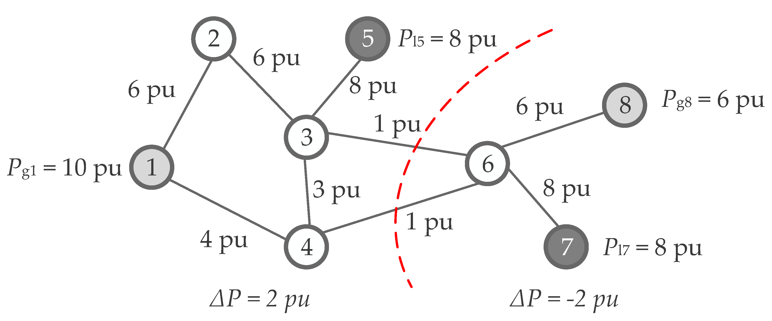
The current trends in EPS development indicate an increasing level of penetration of RES both in the distribution network in terms of distributed generation (DG) as well as the transmission system mostly in terms of wind parks. Many of these belong to the Converter-Interfaced Generation (CIG) type of units not contributing inherently to system inertia. Consequently, this trend results in the decrease and time volatility of EPS inertia masses since conventional power plants based on synchronous machine technology (coal and nuclear) are scheduled for closure, and RES availability significantly depends on weather conditions. In this way, spinning reserves are difficult to predict as are frequency excursions after power imbalance events [29], both in terms of frequency nadir as well as RoCoF. This means that the existing solutions for assuring EPS frequency stability need to be updated in order to adjust to volatile conditions in real time.
We consider that the coordination of multiple SIPS will be crucial in the future for performing a set of ultimate remedial actions involving load curtailment (UFLS) and system splitting (ICI). In the upcoming subsections, all relevant information about such a coordination between SIPS is provided, including the modelling of the electrical network and its elements, UFLS and a wide-area monitoring system (WAMS) as a provider of real-time system measurements.

2.1. Network

In this paper, the authors decided to employ one of the most commonly used test networks for such purposes, an IEEE 39-bus test system also known as the New England test system. It consists of 10 synchronous generators, 34 transmission lines (modelled with π sections), 12 transformers and 19 equivalent loads. The synchronous machines are modelled with a sixth-order representation along with respective governors and automatic voltage controllers. As most of the machines in this specific network are part of thermal power plants (five nuclear and three coal), the IEEEG1 governor model is used for all of them. For the sole hydro power plant (denoted as G10 in Figure 1), the IEEEG3 governor model is assumed. As for the excitation controller, all machines are equipped with an IEEET1 excitation model. Since power oscillation damping is not the focus of our work, power system stabilizers are not activated. The synchronous machine G1 represents the remaining part of the network, to which New England is interconnected. More information about the test system parameters can be accessed in [30].
Based on the technical reference [30], the rated current of an individual 345-kV transmission line is 1000 A. In terms of active power, this means approximately 600 MW of transmission capacity. G1 located at bus 39 is connected to two neighboring buses (i.e., bus 1 and bus 9) by means of double circuit lines, which corresponds to a doubled transmission capacity of 1200 MW.

2.2. UFLS Protection

Under-frequency relays, performing the task of UFLS protection, are assumed to be located in all substations that include an equivalent load (see Figure 1). The chosen UFLS setting follows the conventional approach with six stages represented by frequency thresholds and the amount of curtailed load in each of them. We made the decision to deliberately not consider any intentional time delays since it has been proven many times to worsen the EPS frequency response and the selectivity of UFLS [10,21]. Namely, intentional time delays may cause lower frequency nadir due to a slower relay trip signal and the overlapping of (otherwise consecutive) stages. The settings, summarized in Table 1, comply with the latest ENTSO-E regulations [31,32] and have been proven many times as robust. In publications [10,21], the authors regarded a 50% de-loading as the maximum UFLS reach, yet we decided to lower this value to 45% according to the recommendations for the continental European interconnection [31,32].
Since UFLS is to safeguard the overall system integrity, it is up to the transmission system operators (TSOs) to request its general requirements, whereas a tight collaboration with distribution system operators (DSOs) is needed to set up a list of specific medium voltage feeders that are to be included in individual UFLS stages. Usually, a selection of feeders is made based on their yearly or few-month average power consumption. However, on a shorter time scale, power fluctuations might significantly deviate from average values and, therefore, UFLS activation might not always yield the expected results. This is why we consider that real-time power measurements have the potential to improve this setback. This is definitely a requirement for a successful and stable transition into island operation.
One of the most important aspects in EPS modelling for UFLS and islanding studies is to carefully select an appropriate load model. In general, power consumption depends on both the voltage and the frequency. With regard to voltage, the most typical load model representatives are constant impedance (Z), constant current (I), constant power (P) or the exponential model. The latter enables the inclusion of frequency dependence as well. In this way, load modelling plays an important role in ameliorating the consequences of a power imbalance event [33]. It is up to the selected load parameters to determine to what extent this effect is present. One has to approach this task with care since an inappropriate setting could have a direct impact on whether a certain UFLS stage (or even ICI) is activated or not.
There are a lot of differences between the characteristics of a residential, industrial or any other type of load. Additionally, these characteristics are subject to time variation, e.g., seasonal, daily and/or hourly. The most common and, at the same time, the most basic equation representing load voltage and frequency dependence is as follows:
P ( t ) = P 0 ( U ( t ) U 0 ) k pu ( 1 + k pf Δ f ( t ) f 0 ) Q ( t ) = Q 0 ( U ( t ) U 0 ) k qu ( 1 + k qf Δ f ( t ) f 0 )
in which P(t), Q(t), U(t) and ∆f(t) are actual active power, reactive power, voltage magnitude and frequency deviation at the load bus in relation to time, respectively. P0, Q0, U0 and f0 are their corresponding values prior to the imbalance or, in other words, their steady-state values. The four parameters kpu, kqu, kpf and kqf determine how the load will react to variations in frequency and voltage. In this paper, multiple sets of these four coefficients will be used in order to verify EPS frequency response to a wide range of possible structures of consumers represented by an equivalent load. The selected sets of coefficients will include a constant power model, a constant impedance model with neglected frequency dependence, and a combination of voltage and frequency dependence based on the coefficients taken from [34]. For the residential load type, mean values for kpf and kpf are used.
In this paper, feeders controlled by UFLS frequency relays were considered an asset to ICI. Namely, the island power mismatch can be eliminated much more efficiently and accurately by having a possibility to include or exclude certain feeders from the last (or last two in certain cases) ULFS stages.

2.3. Phasor Measurement Units and Wide-Area Monitoring System

Phasor measurement units (PMUs) are handy devices to measure and report voltage and current synchrophasor measurements, frequency and RoCoF with a report rate in the range between 10 and 50/60 Hz, depending on the EPS nominal frequency [35,36,37]. A WAMS system integrates data streams provided by an arbitrary number of PMU devices and enables system operators to have almost real-time insight into the EPS operating conditions (during an ENTSO-E split in January 2021, the report rate was determined as 20 Hz [2]). For the purpose of this paper, PMUs need to be located in (i) all buses that might be subject to islanding and (ii) generator buses. One has to be aware that the number of PMUs could be optimized to provide sufficient system observability, yet this was not the focus of our research at this stage.

3. Methodology

Intentional Controlled Islanding

An EPS can be represented as an undirected graph model G = (V, E), where V denotes the system buses {v1, v2, …, vn}, while E denotes the edges ei,j   E, (i, j = 1, …, n). The latter is associated with the weight w i , j , representing the active power flow on the edge ei,j. A cut-set (2) removes a set of edges with the aim of splitting G into K islands (in this case, two islands V h and V k ) as described in:
cut ( V h ,   V k ) = i V h ,     j V k w i , j ,   h k .
In order to illustrate how the graph theory can be applied to the EPS, an illustrative (fictional) example is shown in Figure 2. The exemplary EPS consists of two generating buses (nodes denoted as 1 and 8) and two load buses (denoted as 5 and 7). Each power line or transformer is represented as a graph edge between two nodes. In order to compute the minimum cut, power lines 3–6 and 4–6 need to be disconnected, which is represented by a red dashed curve. With that action, we impose a certain power mismatch in each of the two formed islands, i.e., a power surplus of ∆P = 2 pu in the first and a power deficit of ∆P = −2 pu in the second. Power rebalancing would, therefore, require tripping some generation in the first island and load shedding in the second.
The optimization approach used in this paper is based on linear programming, more precisely mixed-integer linear programming (MILP). For the sake of simplicity, a DC power flow is used within the optimization for considering both the transmission line’s and the transformer’s active power limits. With that, we accept that losses are neglected but, at the same time, we gain some significant calculation speed. Our assumption was that losses do not have an immense impact on the overall power balancing problem, especially having in mind the uncertainties of actual load characteristics. In addition, with loads introducing quite significant uncertainties, we believe ignoring losses does not deteriorate the situation to an unacceptable level, especially when they are estimated to approximately 1–2% for an IEEE 39-bus test system.
In seeking the best possible power balance, we decided to assume that a governor reaction to frequency deviations is too slow to have a noticeable effect [38]. ICI is expected to activate in case UFLS is not able to rebalance the system by itself. Such conditions are without a doubt accompanied by extreme RoCoF values, which means that the frequency can deteriorate to a very low value in a very short period of time.
We designed the islanding concept to run in two subsequent steps. In the first step, the generated and consumed powers within the island are roughly matched. Seeking a minimum power flow disruption (PFD) is used for the splitting criteria as follows:
min ( i V h ,     j V k | P i , j | + | P j , i | 2 )
To perform the criteria (3) in the undirected graph G = (V, E) with edge weights w i , j , the partitioning cost could be described by:
min ( i , j ) E   1 2 ( 1 z i , j ) w i , j
s . t . ( i , j ) E   z i , j 2
where z i , j is a binary variable determining whether an edge is included in an island or not. By (5), we wanted to avoid single-generator islands in case it generates the lowest possible power by means of a technological minimum.
In this step, the algorithm determines to which island the individual buses will be connected. This is the so-called “island-formation” step which, of course, results in one island having a slight surplus of power and the other a deficit of power. In the second step, the remaining power mismatch will be eliminated by ordering either the blocking or the forced activation of certain feeders in the UFLS stages. In this way, we aim to maximize the supplied EPS load in both islands while fulfilling the frequency stability related constraints:
max i { V h ,   V k } P d , i  
i V h i V k P g , i i V h i V k P d , i
k min · P d , i start P d , i k max · P d , i start
where Pd,i represents the consumption in bus i (index i is selected among load buses in the selected island, either V h or V k ), Pg,i represents the generation at bus i (index i is selected among the generator buses in the selected island, either V h or V k ) and P d , i start represents the consumption at bus i before the main contingency occurs. Factors k min and k max depend on the sign of the power imbalance: in case of a power surplus k min = 0.55 and k max = 1 and in case of a power deficit k min = 0 and k max = 0.55. The value of 0.55 originates from having 55% of the system load in operation after UFLS is fully exhausted (see Table 1). We assumed that each feeder represents a 5% share of the total EPS load and is equipped with a frequency relay that constantly monitors the signal for activation/deactivation. This makes it possible to further decrease the loading in 5% steps.
As an additional constraint, the transmission capacity of the transformers and transmission lines is taken into consideration:
P i , j max δ i δ j X i , j P i , j min
where δ i and δ j denote voltage phase angles at buses i and j, and P i , j min and P i , j max denote the minimum and maximum allowable power transfer over the element between buses i and j with a reactance Xi,j. The DC power flow is used to check whether these limits are violated in the upcoming island formation. If the DC power flow indicates that the expected islands will not be sustainable, a selected cut-set is denoted as inappropriate.
According to (4)–(9), the calculation begins at the moment a contingency is detected by a WAMS system (see Figure 3). Therefore, the frequency relay settings and cut-sets limits are determined before the frequency reaches critical values that require ICI activation. For extreme RoCoF values, such as the one that appeared in Australia in 2016 (6 Hz/s) [3], one could assume several other robust solutions, e.g., either running the algorithm periodically when the EPS is still in the steady-state operating conditions, or considering RoCoF as an additional optimization parameter that would provide an indication on when to initiate the islanding.
In each time step of the simulation, the measurements from PowerFactory, such as bus frequency and load power, are obtained from the Python script, which is used for making a decision whether any actions are required. When a contingency is detected (i.e., the output power of one of the generators drops to zero), (4) and (5) are triggered to find a set of the most suitable lines to trip once the ICI activation frequency threshold is met. Based on this, two islands are expected. The idea is to maximize the overall consumption in both of the islands combined (6), regardless of whether there is a power deficit or a power surplus in individual islands. The condition that has to be considered in the process is that at the moment of islanding, the power generation in both of the islands must be greater than the consumption (7). The taken actions involve the redistribution of UFLS stages by manipulating each load in order to achieve (8). After that, the DC power flow calculation (9) is performed to verify the occurrence of bottlenecks that might endanger the stability of the islands. If there are none, then commands are sent to the load frequency relays carrying new settings. The entire process is performed prior to the first UFLS stage activation. Afterwards, the Python script waits for UFLS or ICI activation.
The approach from Figure 3 was tested using the PowerFactory DIgSILENT 2021 SP 1 software for RMS (root mean square) dynamic simulations in conjunction with Python. Namely, PowerFactory offers a feature of running an arbitrary Python code in each time step of the simulation.

4. Case Study

In order to invoke extreme frequency fluctuations, the tripping of multiple synchronous generators is the most obvious option (as exemplified in the IEEE 118 test system from [10,21] where two generators were tripped to reach and fully exhaust UFLS and eventually activate ICI). However, in this paper we decided to trip G1 instead, which represents an equivalent of the remaining network. It should be noted that generation tripping does not affect the network topology.
Furthermore, multiple scenarios were observed during the operation of all machines due to high system loading. In those conditions, we examined the effect of having different load models, ranging from constant P, constant Z, and down to the exponential model with/without frequency dependence.
In Figure 4, a frequency response of the observed test system is depicted for applying three different load models. As can be seen, the frequency drops below the selected ICI activation threshold in all three cases (see the red horizontal line), whereas the under-frequency protection of generators is activated only when the constant Z load model was used (with or without frequency dependence; see the black line). This is why in the continuation, only the constant Z model (with and without frequency dependence) is considered as a worst-case scenario.
At simulation time t = 1 s, generator G1 is tripped which causes an outage of 2900 MW. Prior to this contingency, the total generation equals 5646 MW. The frequency begins to decay, UFLS is activated and, finally, the system is split in half. The algorithm selected the cut-set on lines 15–16 and 16–17 as the most appropriate (denoted with the red dashed line in Figure 1). Portions of the network that are to operate either in island 1 or island 2 are also clearly marked in Figure 1. Without the coordination between ICI and UFLS, island 1 would initiate island operation with an active power deficit of 2254 MW, whereas island 2 would initiate island operation with a surplus of active power in the amount of 927 MW. Clearly, the mere range or these imbalance values is enough to conclude that both islands have little chance for successful stabilization, which was confirmed by our simulations (depicted with dashed curves in Figure 5 with the legend entry w/o). By applying the presented methodology, the frequency in both islands stabilized successfully (see solid lines in Figure 5 with the legend entry w). The orange and the red curves depict simulation results when the load is modelled with a constant impedance and, therefore, no frequency dependence. The blue and the green curves, on the other hand, additionally consider the load as frequency dependent (legend entry 1 refers to island number 1, legend entry 2 refers to island number 2).
In island 1, apart from UFLS as determined by Table 1, the algorithm dictated an additional disconnection of loads at buses 18, 25, 26, 27, 28, 29 and 31. At the same time, the load at bus 15 was decreased to 30% of its initial value. In island 2, the algorithm suggested to keep loads at buses 20, 21, 22, 23 and 24 in operation. Their tripping in accordance with UFLS was therefore blocked. In addition, the load at bus 16 was scheduled to 85% of its initial value. The analysis clearly showed that our approach has a beneficial impact on EPS operation and increases the probability for avoiding blackouts in critical operating conditions.
The impact of considering the frequency dependence of the load model can be observed by comparing the green and the red dashed curve (island 2), as well as the yellow with the blue curve (island 1), in Figure 5. One can observe slight differences in the overall frequency response. In the case without UFLS-ICI coordination, the frequency overshoot was reduced by 0.4 Hz (from 63.6 Hz to 63.2 Hz). With regard to the post-mortem value of the frequency in both islands, no significant differences can be observed.

5. Conclusions

The presented methodology for the coordination between UFLS and ICI by applying mixed-integer linear programming shows good results in increasing the probability for avoiding blackouts in critical operating conditions. The feasibility of the approach was tested on an IEEE 39-bus test system model, which is most commonly used for this type of research. The combination of minimum power flow disruption and minimum power imbalance is used for determining the most appropriate cut-set. The latter is achieved with the use of flexible UFLS stages.
The concept can be implemented in those EPSs that have WAMS installed with the support from a sufficient number of PMU devices. With regard to EPS modelling, we emphasized the need for putting proper focus on the modelling of the load whenever frequency-related events are simulated. Simulations showed that the selected load model has a huge impact on the EPS frequency response and can, therefore, play a crucial role in how real-life conditions can be represented by the dynamic model.
Results presented in this paper were obtained by means of RMS dynamic simulations. More accurate and realistic EMT dynamic simulations are expected in the near future by using a real-time digital simulator and a hardware-in-the-loop test set-up. Such analysis will consider several realistic limitations that were ignored in this paper, e.g., relay measuring accuracy, relay measuring, tripping delay, etc.

Author Contributions

Conceptualization, U.R. and J.G.; methodology, J.G.; software, J.G.; validation, J.G.; formal analysis, J.G.; investigation, J.G.; resources, R.M. and U.R.; data curation, J.G.; writing—original draft preparation, J.G.; writing—review and editing, R.M. and U.R.; visualization, J.G.; supervision, R.M. and U.R.; project administration, R.M. and U.R.; funding acquisition, R.M. and U.R. All authors have read and agreed to the published version of the manuscript.

Funding

This work was funded by the Slovenian Research Agency through the Electric Power Systems No. P2-0356 research program, the funding mechanism for young researchers and the resource management for low latency reliable communications in smart grids–LoLag, J2-9232 project.

Conflicts of Interest

The authors declare no conflict of interest.

Nomenclature

EPSElectric power system
ICIIntentional controlled islanding
MILPMixed-integer linear programming
RoCoFRate of change of frequency
SIPSSystem integrity protection schemes
UFLSUnder-frequency load shedding
UVLSUnder-voltage load shedding
WAMSWide-area monitoring system
GUndirected graph
VGraph vertices
EGraph edges
ei,jEdge from node i to node j
wi,jWeight edge from node i to node j
z i , j Binary variable showing edge status between node i and node j
Pi,jActive power flow from node i to node j
Xi,jReactance between nodes i and j
δiVoltage angle of ith node
P d , i Load active power at node i after UFLS activation
P d , i start Load active power at node i in steady state
P g , i Generator active power at node i after UFLS activation
k pu Exponential coefficient for voltage dependence of active power
k qu Exponential coefficient for voltage dependence of reactive power
k pf Frequency dependency coefficient for active power
k qf Frequency dependency coefficient for reactive power
{•}0Subscript for variables in steady state
{•}(t)Time-dependent variables
k min Minimum value for a load in pu in island transition
k max Maximum value for a load in pu in island transition

References

  1. Taylor, P.K.C.; Pourbeik, P. IEEE Task Force on Blackout Experience, Mitigation, and Role of New Technologies; IEEE Power and Energy Society: Piscataway, NJ, USA, 2007; Volume 238. [Google Scholar]
  2. ENTSO-E. Continental Europe Synchronous Area Separation on 8 January 2021, Interim Report 2021. Available online: https://eepublicdownloads.azureedge.net/clean-documents/Publications/Position%20papers%20and%20reports/entso-e_CESysSep_interim_report_210225.pdf (accessed on 12 January 2021).
  3. AEMO. Black System South Australia, 28 September 2016: Final Report; Australian Energy Market Operator: Sydney, Australia, 2017. [Google Scholar]
  4. Final Report of the Investigation Committee on the 28 September 2003 Blackout in Italy 2004. Available online: https://eepublicdownloads.entsoe.eu/clean-documents/pre2015/publications/ce/otherreports/20040427_UCTE_IC_Final_report.pdf (accessed on 12 January 2021).
  5. Naglic, M.; Popov, M.; van der Meijden, M.A.M.M.; Terzija, V. Synchronized Measurement Technology Supported Online Generator Slow Coherency Identification and Adaptive Tracking. IEEE Trans. Smart Grid 2020, 11, 3405–3417. [Google Scholar] [CrossRef] [Green Version]
  6. Dabbaghjamanesh, M.; Wang, B.; Kavousi-Fard, A.; Mehraeen, S.; Hatziargyriou, N.D.; Trakas, D.N.; Ferdowsi, F. A Novel Two-Stage Multi-Layer Constrained Spectral Clustering Strategy for Intentional Islanding of Power Grids. IEEE Trans. Power Deliv. 2020, 35, 560–570. [Google Scholar] [CrossRef]
  7. Babaei, M.; Muyeen, S.M.; Islam, S. Transiently Stable Intentional Controlled Islanding Considering Post-Islanding Voltage and Frequency Stability Constraints. Int. J. Electr. Power Energy Syst. 2021, 127, 106650. [Google Scholar] [CrossRef]
  8. Quiros-Tortos, J.; Demetriou, P.; Panteli, M.; Kyriakides, E.; Terzija, V. Intentional Controlled Islanding and Risk Assessment: A Unified Framework. IEEE Syst. J. 2018, 12, 3637–3648. [Google Scholar] [CrossRef] [Green Version]
  9. Tyuryukanov, I.; Popov, M.; van der Meijden, M.A.M.M.; Terzija, V. Slow Coherency Identification and Power System Dynamic Model Reduction by Using Orthogonal Structure of Electromechanical Eigenvectors. IEEE Trans. Power Syst. 2021, 36, 1482–1492. [Google Scholar] [CrossRef]
  10. Teymouri, F.; Amraee, T. An MILP Formulation for Controlled Islanding Coordinated with under Frequeny Load Shedding Plan. Electr. Power Syst. Res. 2019, 171, 116–126. [Google Scholar] [CrossRef]
  11. New, W.C. Load Shedding, Load Restoration, and Generator Protection Using Solid-State and Electromechanical Underfrequency Relays; General Electric Company, Power Systems Management: Atlanta, GA, USA, 1974. [Google Scholar]
  12. Awadalla, M.; Papadopoulos, P.N.; Milanovic, J.V. An Approach to Controlled Islanding Based on PMU Measurements. In 2017 IEEE Manchester PowerTech; IEEE: Manchester, UK, 2017; pp. 1–6. [Google Scholar]
  13. Demetriou, P.; Quiros-Tortos, J.; Kyriakides, E. When to Island for Blackout Prevention. IEEE Syst. J. 2019, 13, 3326–3336. [Google Scholar] [CrossRef]
  14. You, H.; Vittal, V.; Wang, X. Slow Coherency-Based Islanding. IEEE Trans. Power Syst. 2004, 19, 483–491. [Google Scholar] [CrossRef]
  15. Xu, G.; Vittal, V. Slow Coherency Based Cutset Determination Algorithm for Large Power Systems. IEEE Trans. Power Syst. 2010, 25, 877–884. [Google Scholar] [CrossRef]
  16. Xu, G.; Vittal, V.; Meklin, A.; Thalman, J.E. Controlled Islanding Demonstrations on the WECC System. IEEE Trans. Power Syst. 2011, 26, 334–343. [Google Scholar] [CrossRef]
  17. Esmaeilian, A.; Kezunovic, M. Prevention of Power Grid Blackouts Using Intentional Islanding Scheme. IEEE Trans. Ind. Appl. 2017, 53, 622–629. [Google Scholar] [CrossRef]
  18. Rezaee, M.; Moghadam, M.S.; Ranjbar, S. Online Estimation of Power System Separation as Controlled Islanding Scheme in the Presence of Inter-Area Oscillations. Sustain. Energy Grids Netw. 2020, 21, 100306. [Google Scholar] [CrossRef]
  19. Singh, M.; Meera, K.S.; Joshi, P.; Prakash, P. Islanding Scheme for Power Transmission Utilities. In Proceedings of the 2017 6th International Conference on Computer Applications in Electrical Engineering-Recent Advances (CERA), Roorkee, India, 5–7 October 2017; pp. 69–73. [Google Scholar]
  20. Lu, W.; Bésanger, Y.; Zamaï, E.; Radu, D. Blackouts: Description, Analysis and Classification. In Proceedings of the WSEAS International Conference on Electric Power Systems, Lisbon, Portugal, 22–24 September 2006; pp. 429–434. [Google Scholar]
  21. Teymouri, F.; Amraee, T.; Saberi, H.; Capitanescu, F. Toward Controlled Islanding for Enhancing Power Grid Resilience Considering Frequency Stability Constraints. IEEE Trans. Smart Grid 2019, 10, 1735–1746. [Google Scholar] [CrossRef]
  22. Shao, H.; Norris, S.; Lin, Z.; Bialek, J. Determination of When to Island by Analysing Dynamic Characteristics in Cascading Outages. In Proceedings of the 2013 IEEE Grenoble Conference, Grenoble, France, 16–20 June 2013; pp. 1–6. [Google Scholar]
  23. Adibi, M.M.; Kafka, R.J. Power System Restoration Issues. IEEE Comput. Appl. Power 1991, 4, 19–24. [Google Scholar] [CrossRef]
  24. Adibi, M.M.; Kafka, L.R.J.; Milanicz, D.P. Expert System Requirements for Power System Restoration. IEEE Trans. Power Syst. 1994, 9, 1592–1600. [Google Scholar] [CrossRef]
  25. Bahrami, M.; Vakilian, M.; Farzin, H.; Lehtonen, M. Multi-Step Island Formation and Repair Dispatch Reinforced by Mutual Assistance after Natural Disasters. Int. J. Electr. Power Energy Syst. 2021, 126, 106572. [Google Scholar] [CrossRef]
  26. Feng, Z.; Niu, W.; Wang, S.; Cheng, C.; Song, Z. Mixed Integer Linear Programming Model for Peak Operation of Gas-Fired Generating Units with Disjoint-Prohibited Operating Zones. Energies 2019, 12, 2179. [Google Scholar] [CrossRef] [Green Version]
  27. Alavi, S.A.; Ilea, V.; Saffarian, A.; Bovo, C.; Berizzi, A.; Seifossadat, S.G. Feasible Islanding Operation of Electric Networks with Large Penetration of Renewable Energy Sources Considering Security Constraints. Energies 2019, 12, 537. [Google Scholar] [CrossRef] [Green Version]
  28. Porzio, G.F.; Nastasi, G.; Colla, V.; Vannucci, M.; Branca, T.A. Comparison of Multi-Objective Optimization Techniques Applied to off-Gas Management within an Integrated Steelwork. Appl. Energy 2014, 136, 1085–1097. [Google Scholar] [CrossRef]
  29. SPD—Inertia TF Inertia and Rate of Change of Frequency (ROCOF) 2020. Available online: https://eepublicdownloads.azureedge.net/clean-documents/SOC%20documents/Inertia%20and%20RoCoF_v17_clean.pdf (accessed on 12 January 2021).
  30. Demetriou, P.; Asprou, M.; Quiros-Tortos, J.; Kyriakides, E. Dynamic IEEE Test Systems for Transient Analysis. IEEE Syst. J. 2017, 11, 2108–2117. [Google Scholar] [CrossRef]
  31. SAFA for RGCE, E.-E. Annex 5: Policy on Emergency and Restoration 2019. Available online: https://eepublicdownloads.entsoe.eu/clean-documents/Publications/SOC/safa/5_-_Policy__on_Emergency_and_Restoration.pdf (accessed on 12 January 2021).
  32. Commision Regulation (EU). 2017/2196—Establishing a Network Code on Electricity Emergency and Restoration; Official Journal of the European Union, EU: Luxembourg, 2017. [Google Scholar]
  33. Rudez, U.; Mihalic, R. WAMS-Based Underfrequency Load Shedding with Short-Term Frequency Prediction. IEEE Trans. Power Deliv. 2016, 31, 1912–1920. [Google Scholar] [CrossRef]
  34. Machowski, J.; Bialek, J.W.; Bumby, J.R. Power System Dynamics: Stability and Control; John Wiley & Sons, Ltd.: Abingdon, UK, 2008. [Google Scholar]
  35. Castello, P.; Lixia, M.; Muscas, C.; Pegoraro, P.A. Impact of the Model on the Accuracy of Synchrophasor Measurement. IEEE Trans. Instrum. Meas. 2012, 61, 2179–2188. [Google Scholar] [CrossRef]
  36. IEEE. IEEE Standard for Synchrophasor Measurements for Power Systems; IEEE Std C371181-2011 Revis. IEEE Std C37118-2005; IEEE: Piscataway, NJ, USA, 2011; pp. 1–61. [Google Scholar] [CrossRef]
  37. IEEE. IEEE Standard for Synchrophasor Data Transfer for Power Systems; IEEE Std C371182-2011 Revis. IEEE Std C37118-2005; IEEE: Piscataway, NJ, USA, 2011; pp. 1–53. [Google Scholar] [CrossRef]
  38. Esmaili, M.; Ghamsari-Yazdel, M.; Amjady, N.; Chung, C.Y. Convex Model for Controlled Islanding in Transmission Expansion Planning to Improve Frequency Stability. IEEE Trans. Power Syst. 2021, 36, 58–67. [Google Scholar] [CrossRef]
Figure 1. Single-line diagram of an IEEE 39-bus test system and the simulation results.
Energies 14 02790 g001
Figure 2. Illustrative (fictional) example of using the graph theory in an EPS.
Energies 14 02790 g002
Figure 3. Overall algorithm structure of the proposed approach.
Energies 14 02790 g003
Figure 4. Frequency response dependence on the selected load model.
Energies 14 02790 g004
Figure 5. Electrical-voltage frequencies at buses 3 and 20.
Energies 14 02790 g005
Table 1. Applied UFLS settings.
StageI.II.III.IV.V.VI.ICI
Load shed (% of total load)101010555/
Frequency threshold (Hz)59.559.35958.658.358.057.6
Publisher’s Note: MDPI stays neutral with regard to jurisdictional claims in published maps and institutional affiliations.

