
A Nonlinear Control Strategy for DC-DC Converter with Unknown Constant Power Load Using Damping and Interconnection Injecting


Abstract
:1. Introduction
2. Stability Analysis of DDBC Converter with CPL
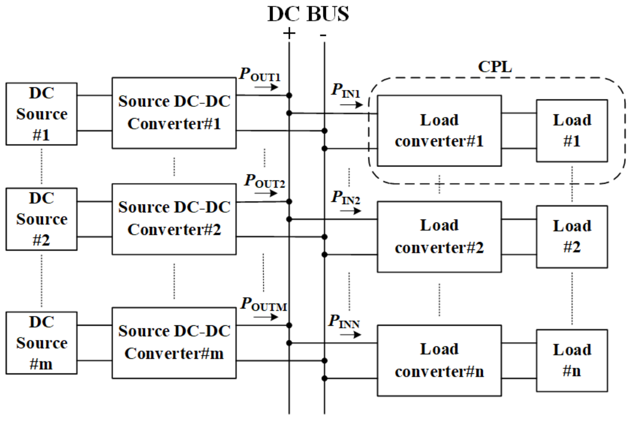
2.1. Constant Power Load Characteristic
2.2. Stability Analysis of DDBC with CPL Based on Passivity
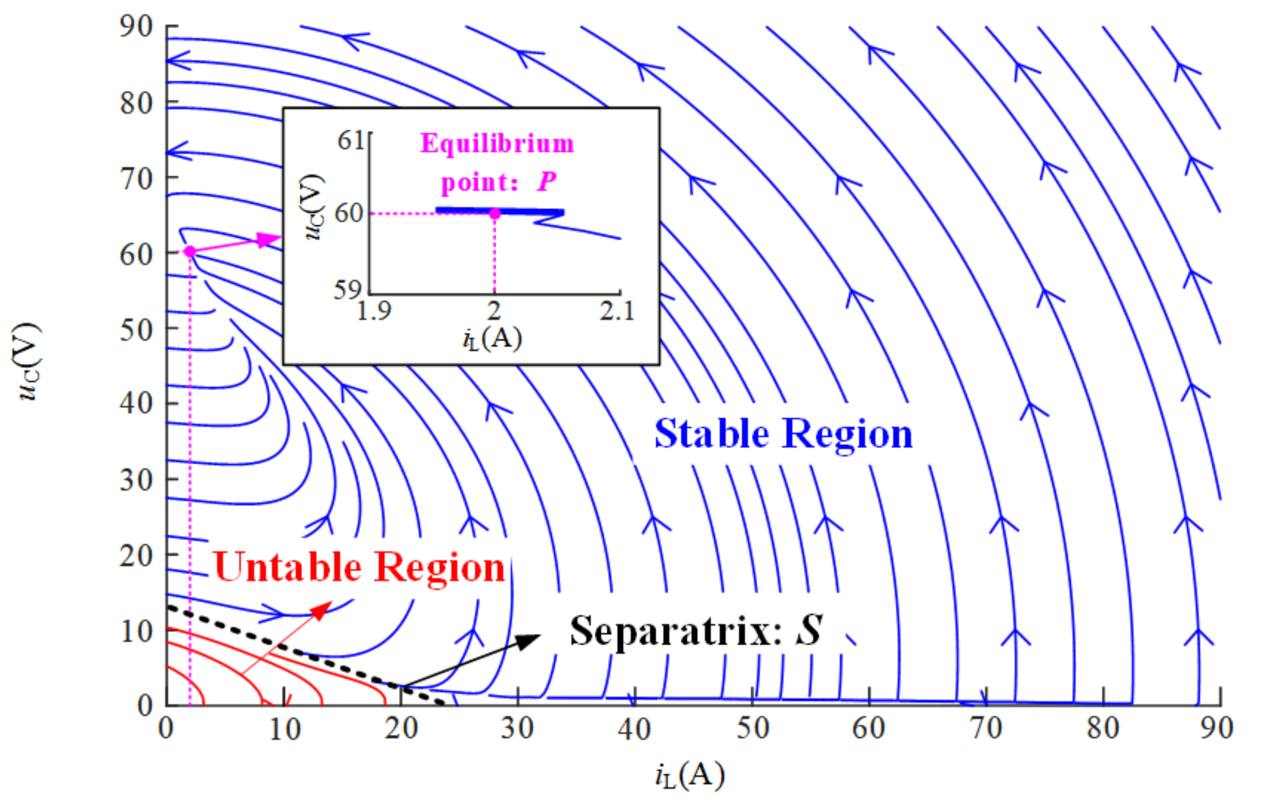
2.2.1. Effect of CPL on Stability of DDBC
2.2.2. Passivity Analysis of DDBC with CPL
3. IPBC of DDBC Based on PCHD Model
3.1. PCHD Model of DDBC
3.2. IPBC Design of DDBC
4. Unknown Nonlinear Power Observer and Preferences in IPBC
4.1. Nonlinear Power Observer of Unknown CPL
4.2. Design of Damping Injecting and Conductance Injecting for IPBC
4.3. Design of Interconnection Injecting for IPBC
- (1)
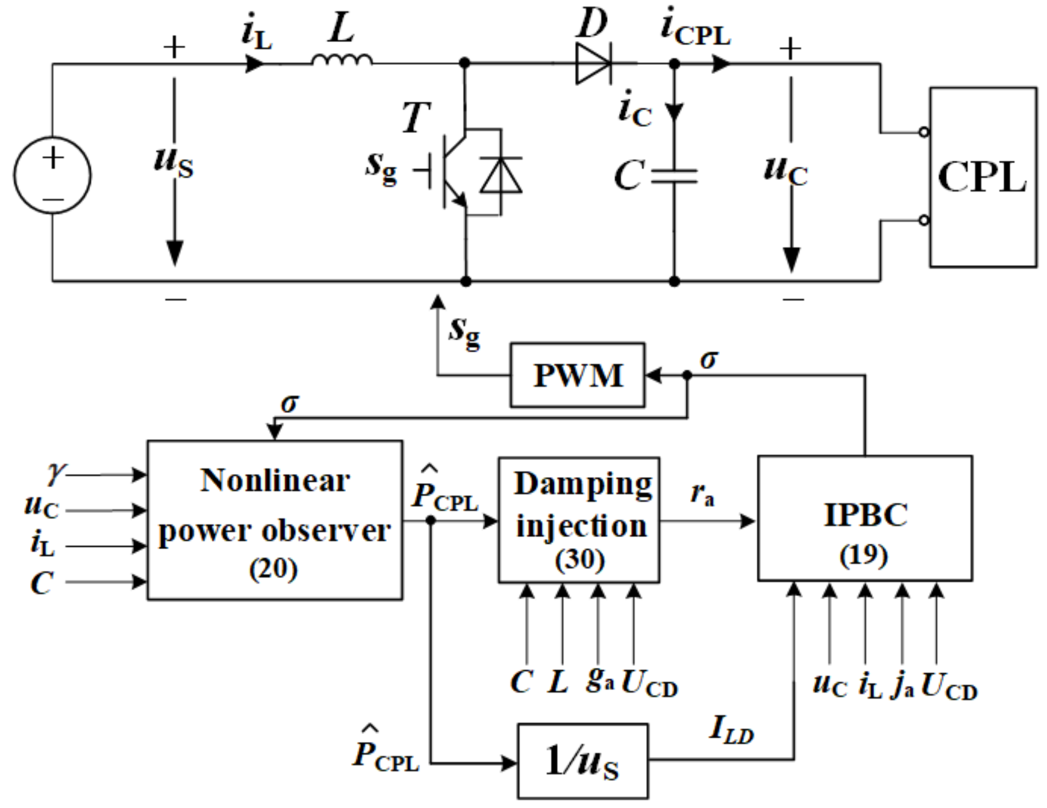
- First, the parameters γ, ra, and ja are designed according to (23), (30) and (31).
- (2)
- Second, the power of CPL is estimated according to (20), and ILD is calculated with the measured input voltage.
- (3)
- Finally, the duty cycle is calculated according to (19) with determined parameters and measured inductor current, output voltage, and input voltage.
5. Simulation and Experimental Results
5.1. Simulation Results
5.1.1. Tuning of Design Parameters
- NPO Gain
- 2.
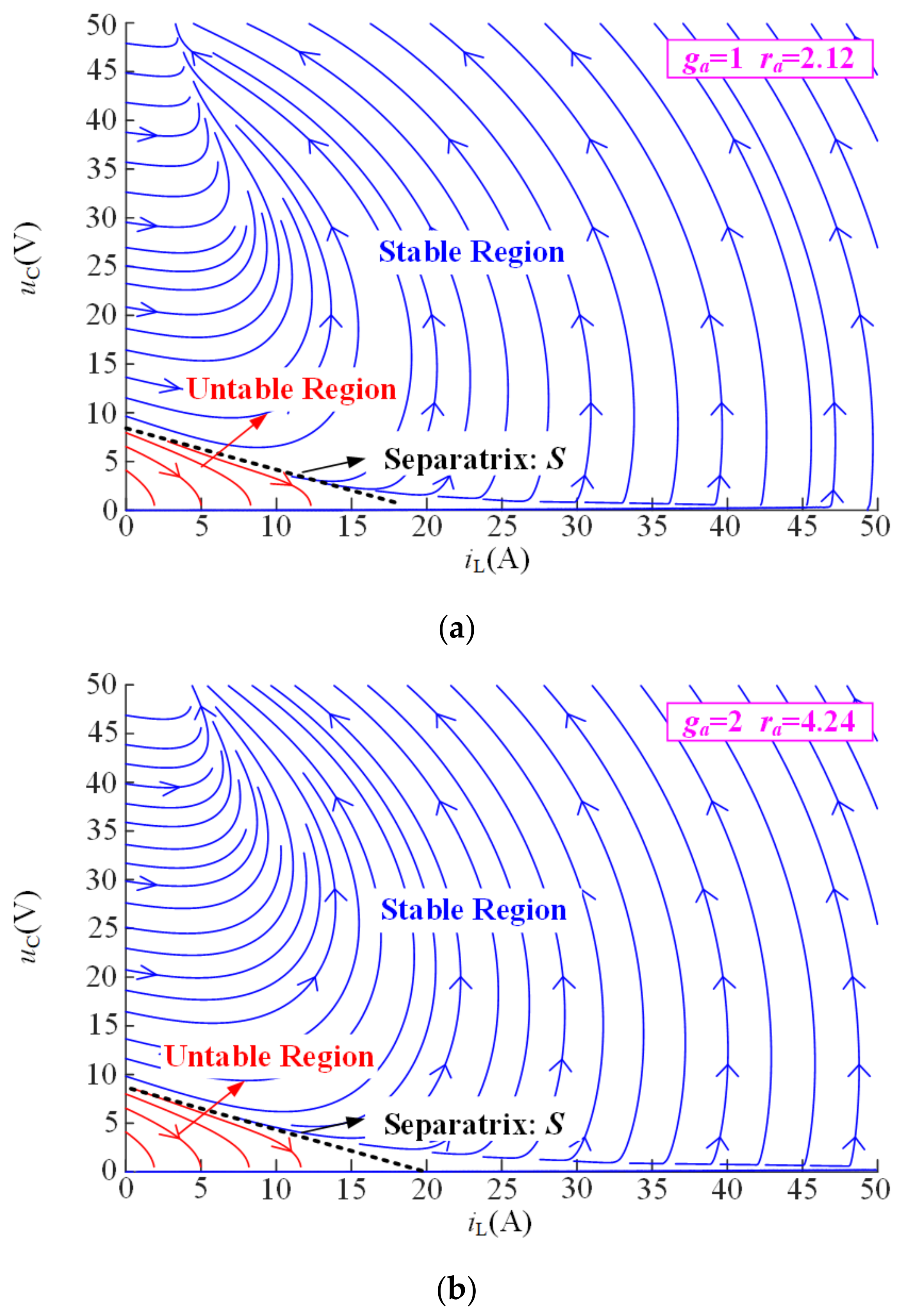
- Positive Damping Injecting and Conductance Injecting
- 3.
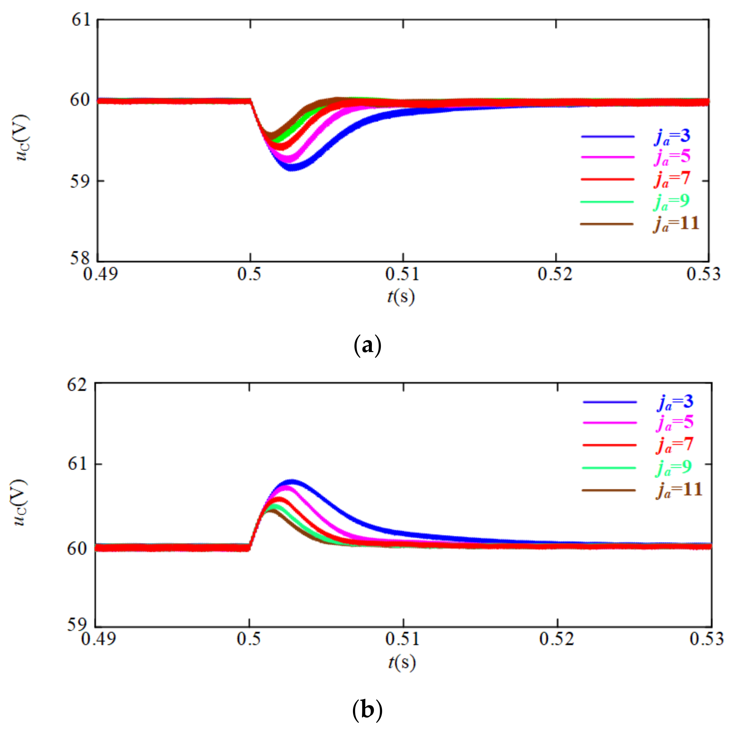
- Interconnection Injecting
5.1.2. Simulation Verification
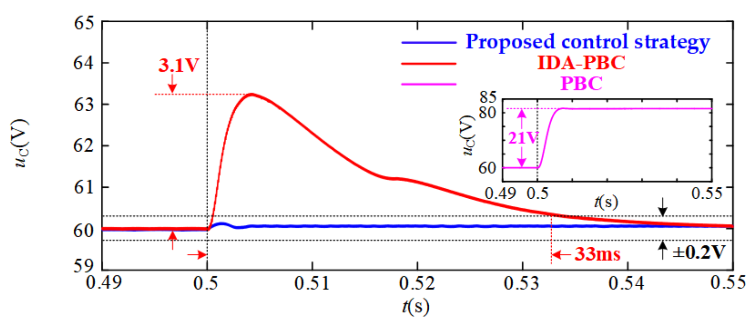
- Step Change in uS
- 2.
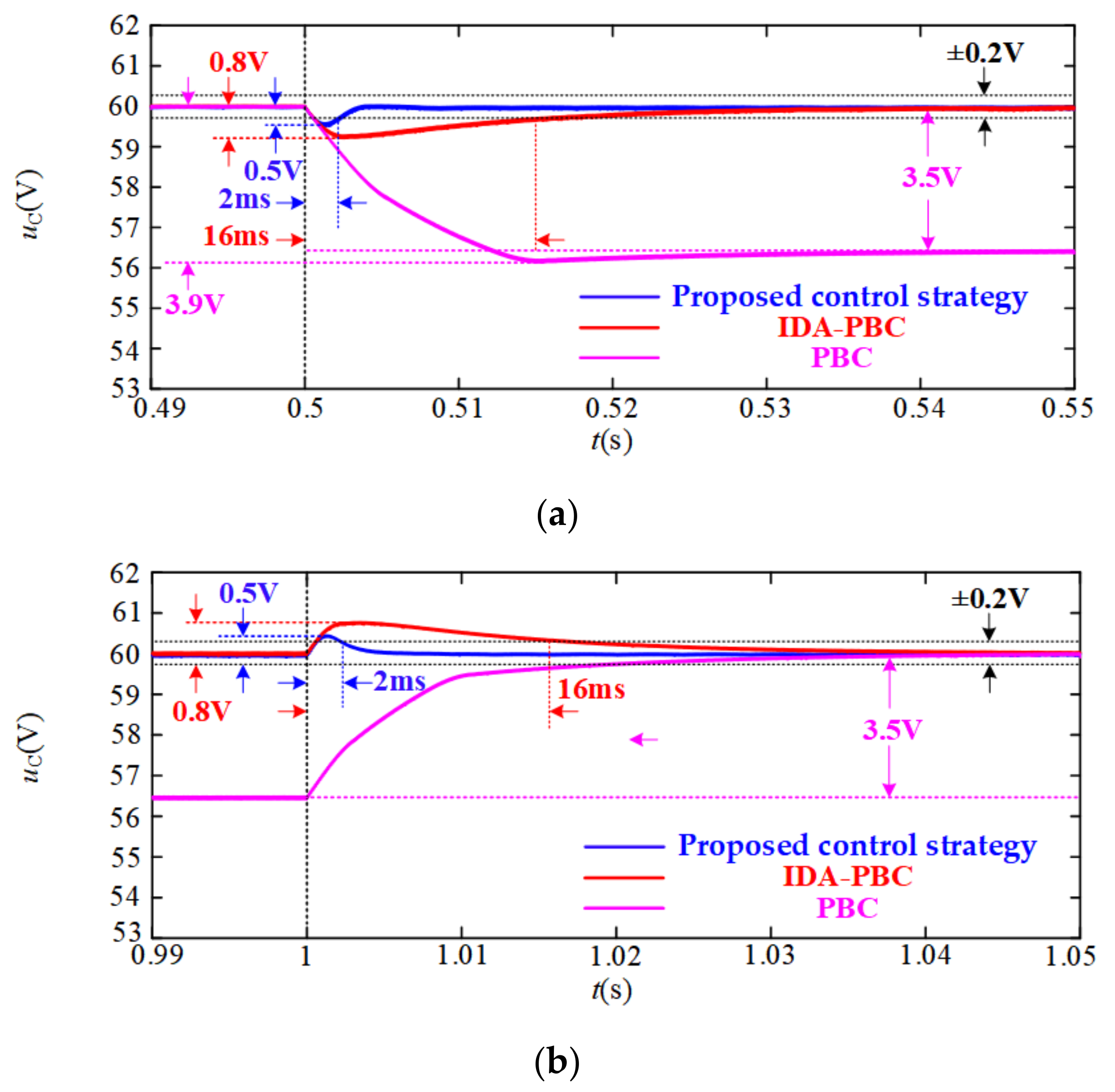
- Step Change in PCPL
5.2. Experimental Results
- Step Change in uS
- 2.
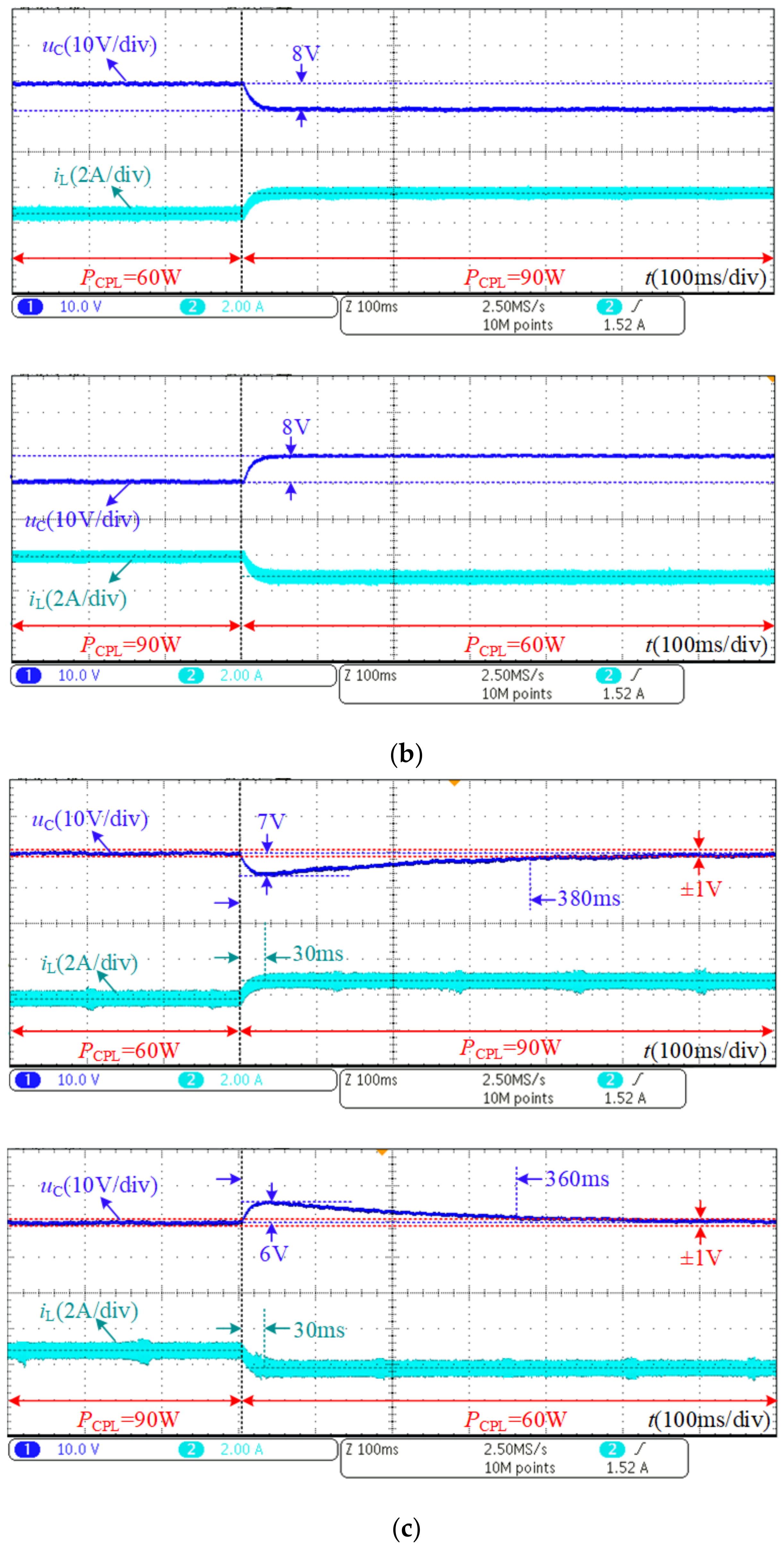
- Step Change in PCPL
6. Conclusions
Author Contributions
Funding
Institutional Review Board Statement
Informed Consent Statement
Data Availability Statement
Conflicts of Interest
Appendix A


References
- Hamzeh, M.; Ghazanfari, A.; Mohamed, Y.A.-R.I.; Karimi, Y. Modeling and Design of an Oscillatory Current-Sharing Control Strategy in DC Microgrids. IEEE Trans. Ind. Electron. 2015, 62, 6647–6657. [Google Scholar] [CrossRef]
- Huang, P.; Liu, P.; Xiao, W.; El Moursi, M.S. A novel droop-based average voltage sharing control strategy for DC mi-crogrids. IEEE Trans. Smart Grid 2015, 6, 1096–1106. [Google Scholar] [CrossRef]
- Kolluri, R.R.; Mareels, I.; De Hoog, J. Controlling DC microgrids in communities, buildings and data centers. IET Smart Grid 2020, 3, 376–384. [Google Scholar] [CrossRef]
- Dragičević, T.; Lu, X.; Vasquez, J.C.; Guerrero, J.M. DC Microgrids—Part I: A Review of Control Strategies and Stabiliza-tion Techniques. IEEE Trans. Power Electron. 2016, 31, 4876–4891. [Google Scholar]
- Su, M.; Liu, Z.J.; Sun, Y.; Han, H.; Hou, X. Stability analysis and stabilization methods of DC microgrid with multiple parallel-connected DC-DC converters Loaded by CPLs. IEEE Trans. Smart Grid 2018, 9, 132–142. [Google Scholar] [CrossRef]
- Farsizadeh, H.; Gheisarnejad, M.; Mosayebi, M.; Rafiei, M.; Khooban, M.H. An Intelligent and Fast Controller for DC/DC Converter Feeding CPL in a DC Microgrid. IEEE Trans. Circuits Syst. II Express Briefs 2020, 67, 1104–1108. [Google Scholar] [CrossRef]
- Hamidi, S.A.; Nasiri, A. Stability Analysis of a DC-DC Converter for Battery Energy Storage System Feeding CPL. In Proceedings of the 2015 IEEE International Telecommunications Energy Conference (INTELEC), Osaka, Japan, 18–22 October 2015; pp. 1–5. [Google Scholar]
- El Aroudi, A.; Haroun, R.; Al-Numay, M.S.; Calvente, J.; Giral, R. Fast-Scale Stability Analysis of a DC–DC Boost Converter With a Constant Power Load. IEEE J. Emerg. Sel. Top. Power Electron. 2021, 9, 549–558. [Google Scholar] [CrossRef]
- Lu, X.; Sun, K.; Guerrero, J.M.; Vasquez, J.C.; Huang, L.; Wang, J. Stability Enhancement Based on Virtual Impedance for DC Microgrids with Constant Power Loads. IEEE Trans. Smart Grid 2015, 6, 2770–2783. [Google Scholar] [CrossRef]
- Azizi, A.; Hamzeh, M. Stability Analysis of a DC Microgrid With Constant Power Loads Using Small-Signal Equivalent Circuit. In Proceedings of the 2020 11th Power Electronics, Drive Systems, and Technologies Conference (PEDSTC), Tehran, Iran, 4–6 February 2020; pp. 1–6. [Google Scholar]
- Liu, S.; Zhu, W.; Cheng, Y.; Xing, B. Modeling and Small-Signal Stability Analysis of an Islanded DC Microgrid with Dynamic Loads. In Proceedings of the 2015 IEEE 15th International Conference on Environment and Electrical Engineering (EEEIC), Rome, Italy, 10–13 June 2015; pp. 866–871. [Google Scholar]
- Yue, X.; Wang, X.; Blaabjerg, F. Review of Small-Signal Modeling Methods Including Frequency-Coupling Dynamics of Power Converters. IEEE Trans. Power Electron. 2019, 34, 3313–3328. [Google Scholar] [CrossRef]
- Tu, G.; Li, Y.; Xiang, J. A nonlinear boundary controller for buck converters feeding constant-power loads. In Proceedings of the 2017 36th Chinese Control Conference (CCC), Dalian, China, 26–28 July 2017; pp. 698–703. [Google Scholar]
- Bacha, S.; Munteanu, I.; Bratcu, A.I. Power Electronic Converters Modeling and Control; Springer: London, UK, 2014. [Google Scholar]
- Jiuhe, W. Advanced Nonlinear Control Theory and Application; Science Press: Beijing, China, 2011. [Google Scholar]
- Zhaohui, G.; Hui, L.; Xiaobin, Z. Exact Linearization and Optimal Tracking Control of Boost Converter with Constant Power Loads. Proc. CSEE 2007, 27, 70–75. (In Chinese) [Google Scholar]
- Arora, S.; Balsara, P.T.; Bhatia, D.K. Input–Output Linearization of a Boost Converter with Mixed Load (Constant Voltage Load and Constant Power Load). IEEE Trans. Power Electron. 2018, 34, 815–825. [Google Scholar] [CrossRef]
- Jingqing, H. Active Disturbance Rejection Control Technique—The Technique for Estimating and Compensating the Uncer-Tainties; National Defense Industry Press: Beijing, China, 2008. [Google Scholar]
- Ahmad, S.; Ahmad, A. Active disturbance rejection control of DC–DC boost converter: A review with modifications for improved performance. IET Power Electron. 2019, 12, 2095–2107. [Google Scholar] [CrossRef]
- Trevino, B.A.M.; El Aroudi, A.; Vidal-Idiarte, E.; Cid-Pastor, A.; Martinez-Salamero, L. Sliding-mode control of a boost converter under constant power loading conditions. IET Power Electron. 2019, 12, 521–529. [Google Scholar] [CrossRef]
- Wu, J.; Lu, Y. Adaptive Backstepping Sliding Mode Control for Boost Converter with Constant Power Load. IEEE Access 2019, 7, 50797–50807. [Google Scholar] [CrossRef]
- Ortega, R.; Loría, A.; Nicklasson, P.J.; Sira-Ramírez, H. Passivity-Based Control of Euler-Lagrange Systems; Springer: London, UK, 1998. [Google Scholar]
- Salimi, M.; Eghlim, A.L. Passivity-Based Control of the DC-DC buck Converters in High-Power Applications. In Proceedings of the TENCON 2014—2014 IEEE Region 10 Conference, Bangkok, Thailand, 22–25 October 2014; pp. 1–6. [Google Scholar]
- Linares-Flores, J.; Barahona-Avalos, J.L.; Sira-Ramirez, H.; Contreras-Ordaz, M.A. Robust Passivity-Based Control of a Buck–Boost-Converter/DC-Motor System: An Active Disturbance Rejection Approach. IEEE Trans. Ind. Appl. 2012, 48, 2362–2371. [Google Scholar] [CrossRef]
- Hernández-Márquez, E.; Silva-Ortigoza, R.; García-Sánchez, J.R.; Marcelino-Aranda, M.; Saldaña-González, G. A DC/DC Buck-Boost Converter–Inverter–DC Motor System: Sensorless Passivity-Based Control. IEEE Access 2018, 6, 31486–31492. [Google Scholar] [CrossRef]
- Wang, B.; Feng, H.; Bingyuan, W.; Hui, F. The Buck-Boost Converter Adopting Passivity-Based Adaptive Control Strategy and Its Application. In Proceedings of the 7th International Power Electronics and Motion Control Conference, Harbin, China, 2–5 June 2012; Volume 3, pp. 1877–1882. [Google Scholar]
- Ortega, R.; van der Schaft, A.; Maschke, B.; Escobar, G. Interconnection and damping assignment passivity-based control of port-controlled Hamiltonian systems. Automatica 2002, 38, 585–596. [Google Scholar] [CrossRef] [Green Version]
- Zeng, J.; Zhang, Z.; Qiao, W. An Interconnection and Damping Assignment Passivity-Based Controller for a DC–DC Boost Converter with a Constant Power Load. IEEE Trans. Ind. Appl. 2014, 50, 2314–2322. [Google Scholar] [CrossRef]
- Pang, S.; Nahid-Mobarakeh, B.; Pierfederici, S.; Huangfu, Y.; Luo, G.; Gao, F. Toward Stabilization of Constant Power Loads Using IDA-PBC for Cascaded LC Filter DC/DC Converters. IEEE J. Emerg. Sel. Top. Power Electron. 2021, 9, 1302–1314. [Google Scholar] [CrossRef]
- Bottrell, N.; Prodanovic, M.; Green, T.C. Dynamic Stability of a Microgrid with an Active Load. IEEE Trans. Power Electron. 2013, 28, 5107–5119. [Google Scholar] [CrossRef] [Green Version]
- Kovar, J.; Kolka, Z.; Biolek, D. Symbolic Analysis of DC-DC Converters Using Generalized Averaged Model of PWM Switch. In Proceedings of the 2009 MIXDES-16th International Conference Mixed Design of Integrated Circuits & Systems, Lodz, Poland, 25–27 June 2009; pp. 577–580. [Google Scholar]
- Wang, J.; Mu, X.; Li, Q.-K. Study of Passivity-Based Decoupling Control of T-NPC PV Grid-Connected Inverter. IEEE Trans. Ind. Electron. 2017, 64, 7542–7551. [Google Scholar] [CrossRef]
- Gandhi, M.R.; Rathore, S. Comparative Study of Different Passivity-Based Non-linear Control of DC-DC Boost Converter. In Proceedings of the 2019 Innovations in Power and Advanced Computing Technologies (i-PACT), Vellore, India, 22–23 March 2019; Volume 1, pp. 1–7. [Google Scholar]
- He, W.; Ortega, R. Design and Implementation of Adaptive Energy Shaping Control for DC–DC Converters With Constant Power Loads. IEEE Trans. Ind. Inform. 2019, 16, 5053–5064. [Google Scholar] [CrossRef]
- He, W.; Soriano-Rangel, C.A.; Ortega, R.; Astolfi, A.; Mancilla-David, F.; Li, S. DC-DC Buck-Boost Converters with Unknown CPL: An Adaptive PBC. In Proceedings of the 2018 Annual American Control Conference (ACC), Milwaukee, WI, USA, 27–29 June 2018; pp. 6749–6754. [Google Scholar]
- Xu, Q.; Xu, Y.; Zhang, C.; Wang, P. A Robust Droop-Based Autonomous Controller for Decentralized Power Sharing in DC Microgrid Considering Large-Signal Stability. IEEE Trans. Ind. Inform. 2019, 16, 1483–1494. [Google Scholar] [CrossRef]
- Xu, Q.; Zhang, C.; Wen, C.; Wang, P. A Novel Composite Nonlinear Controller for Stabilization of Constant Power Load in DC Microgrid. IEEE Trans. Smart Grid 2019, 10, 752–761. [Google Scholar] [CrossRef]


| Symbols | Parameter Names | Values |
|---|---|---|
| uS | Input voltage | 30 V |
| UCD | Desired average output voltage | 60 V |
| ILD | Desired average inductor current | 2 A |
| PCPL | Rated power | 60 W |
| C | Capacitance | 940 μF |
| L | Inductance | 2 mH |
| fS | Switching frequency | 10 kHz |
| ja | Interconnection injecting | 7 |
| ra | Positive damping injecting | 6.36 |
| ga | Conductance injecting | 3 |
| γ | Power observer gain | 2000 |
| Input Voltage Disturbance | Control Strategy | Fluctuation Peak Value of uC(V) | Transient Time of uC (ms) | Steady State Error (V) |
|---|---|---|---|---|
| 30 V to 40 V | Proposed control strategy | ≈0 | ≈0 | ≈0 |
| PBC [22] | 21 | - | 21 | |
| IDA-PBC [28] | 3.1 | 33 | ≈0 |
| CPL Disturbance | Control Strategy | Fluctuation Peak Value of uC(V) | Transient Time of uC (ms) | Steady State Error (V) |
|---|---|---|---|---|
| 60 W to 90 W | Proposed control strategy | 0.5 | 2 | ≈0 |
| PBC [22] | 3.9 | - | 3.5 | |
| IDA-PBC [28] | 0.8 | 16 | ≈0 | |
| 90 W to 60 W | Proposed control strategy | 0.5 | 2 | ≈0 |
| PBC [22] | 3.5 | - | 3.5 | |
| IDA-PBC [28] | 0.8 | 16 | ≈0 |
| Input Voltage Disturbance | Control Strategy | Fluctuation Peak Value of uC(V) | Transient Time of uC (ms) | Steady State Error (V) |
|---|---|---|---|---|
| 30 V to 40 V | Proposed control strategy | ≈0 | ≈0 | ≈0 |
| PBC [22] | 23 | - | 23 | |
| IDA-PBC [28] | 5 | 500 | ≈0 |
| CPL Disturbance | Control Strategy | Fluctuation Peak Value of uC(V) | Transient Time of uC (ms) | Steady State Error (V) |
|---|---|---|---|---|
| 60 W to 90 W | Proposed control strategy | <1 | ≈0 | ≈0 |
| PBC [22] | 8 | - | 8 | |
| IDA-PBC [28] | 7 | 380 | ≈0 | |
| 90 W to 60 W | Proposed control strategy | <1 | ≈0 | ≈0 |
| PBC [22] | 8 | - | 8 | |
| IDA-PBC [28] | 6 | 360 | ≈0 |
Publisher’s Note: MDPI stays neutral with regard to jurisdictional claims in published maps and institutional affiliations. |
© 2021 by the authors. Licensee MDPI, Basel, Switzerland. This article is an open access article distributed under the terms and conditions of the Creative Commons Attribution (CC BY) license (https://creativecommons.org/licenses/by/4.0/).
Share and Cite
Wang, M.; Tang, F.; Wu, X.; Niu, J.; Zhang, Y.; Wang, J. A Nonlinear Control Strategy for DC-DC Converter with Unknown Constant Power Load Using Damping and Interconnection Injecting. Energies 2021, 14, 3031. https://doi.org/10.3390/en14113031
Wang M, Tang F, Wu X, Niu J, Zhang Y, Wang J. A Nonlinear Control Strategy for DC-DC Converter with Unknown Constant Power Load Using Damping and Interconnection Injecting. Energies. 2021; 14(11):3031. https://doi.org/10.3390/en14113031
Chicago/Turabian StyleWang, Mian, Fen Tang, Xuezhi Wu, Jingkai Niu, Yajing Zhang, and Jiuhe Wang. 2021. "A Nonlinear Control Strategy for DC-DC Converter with Unknown Constant Power Load Using Damping and Interconnection Injecting" Energies 14, no. 11: 3031. https://doi.org/10.3390/en14113031