Review

The Importance of Optical Fibres for Internal Temperature Sensing in Lithium-ion Batteries during Operation

1
Department of Energy and Process Engineering & ENERSENSE, NTNU, 7491 Trondheim, Norway
2
Department of Electronic Systems & ENERSENSE, NTNU, 7491 Trondheim, Norway
*
Author to whom correspondence should be addressed.
Energies 2021, 14(12), 3617; https://doi.org/10.3390/en14123617
Submission received: 14 April 2021 / Revised: 19 May 2021 / Accepted: 15 June 2021 / Published: 17 June 2021
(This article belongs to the Special Issue Advanced Technology to Improve Energy Efficiency and Storage)

Abstract

:
Lithium-ion batteries (LiBs) are widely used as energy storage systems (ESSs). The biggest challenge they face is retaining intrinsic health under all conditions, and understanding internal thermal behaviour is crucial to this. The key concern is the potentially large temperature differences at high charge/discharge rates. Excess heat created during charge/discharge will accelerate irreversible aging, eventually leading to failure. As a consequence, it is important to keep battery states within their safe operating range, which is determined by voltage, temperature, and current windows. Due to the chemically aggressive and electrically noisy environment, internal temperature measurement is difficult. As a result, non-invasive sensors must be physically stable, electromagnetic interference-resistant, and chemically inert. These characteristics are provided by fibre Bragg grating (FBG) sensors, which are also multiplexable. This review article discusses the thermal problems that arise during LiB use, as well as their significance in terms of LiB durability and protection. FBG-based sensors are described as a technology, with emphasis on their importance for direct temperature measurement within the LiB cell.

1. Introduction

Lithium-ion batteries (LiBs) are commonly used as energy storage systems (ESSs) in portable devices, and hybrid and pure electric vehicles due to their high specific capacity, long life cycle, low self-discharge and compatibility with existing electric infrastructure [1,2,3,4,5]. The first and foremost challenge in developing a LiB device is to maintain its intrinsic stability under both normal and irregular circumstances. Awareness of internal thermal activity is key to this [6,7,8]. The main issue is the substantial temperature increase at elevated charge/discharge rates [5,9,10,11]. Excess heat produced during charge/discharge or in the presence of short circuits can cause irreversible cell damage and eventually lead to explosion or combustion [12,13]. Therefore, maintaining battery states within their healthy operating range, which is bounded by voltage, temperature, and current windows [14], is critical. A Battery Management System (BMS), including Thermal Management System (TMS), is a critical component for tracking and managing these states to ensure safe, stable and long-lived battery activity.
Literature indicates that the temperature near the cathode is higher than near the anode due to the lower electrical conductivity of most cathode active materials and the local reversible heat effects [7,15]. To establish a satisfactory thermal management strategy and increase LiB efficiency and lifespan, monitoring and management of both internal and external temperature is essential [16,17]. LiBs are typically thermally controlled on or near their surface using thermocouples or electro-mechanical sensors [18,19]. However, external surface sensors do not provide an accurate measurement of the specific internal thermal gradients and can be influenced by the external environment [20]. Internal control is difficult due to the chemically hostile and electrically noisy atmosphere. Therefore, non-invasive sensors that are mechanically robust, immune to electromagnetic interference and chemically inert are required. Fibre Bragg grating (FBG) sensors exhibit these characteristics and are also very thin, mobile, and have multiplexing capabilities. Moreover, these are chemically inert and have the ability of monitoring multiple points in the same optical fibre at once [10]. Many of these features make them ideal for tracking LiBs and fuel cells [8,21,22,23,24,25]. FBG sensors have also been used to track electrode strain in LiBs [26].
Previous reviews have covered different temperature indication methods applicable to LiBs extensively [27]. Still, the specific case of measuring the internal temperature with fibre-optic sensors should be addressed further, as this is where the optical sensors are considered to be superior over the electrical alternatives. Therefore, the challenge with the temperature/strain cross-sensitivity in the fibre-optic sensors requires additional study to achieve accurate internal temperature measurement. This is especially important in larger LiBs (e.g., in cars), where there is limited information on the thermal distributions available in the literature.
This review article covers the thermal issues related to LiB operation, and their importance with regard to LiB longevity and safety. A presentation of FBG-based sensors is given discussing their implementation into LiBs for direct measurement of temperatures within the cell. Finally, areas of research that need attention that are required to improve the utilisation of FBGs in LiBs are discussed in order to improve implementation of optical fibre sensors into battery cells.

2. LiBs and Thermal Issues
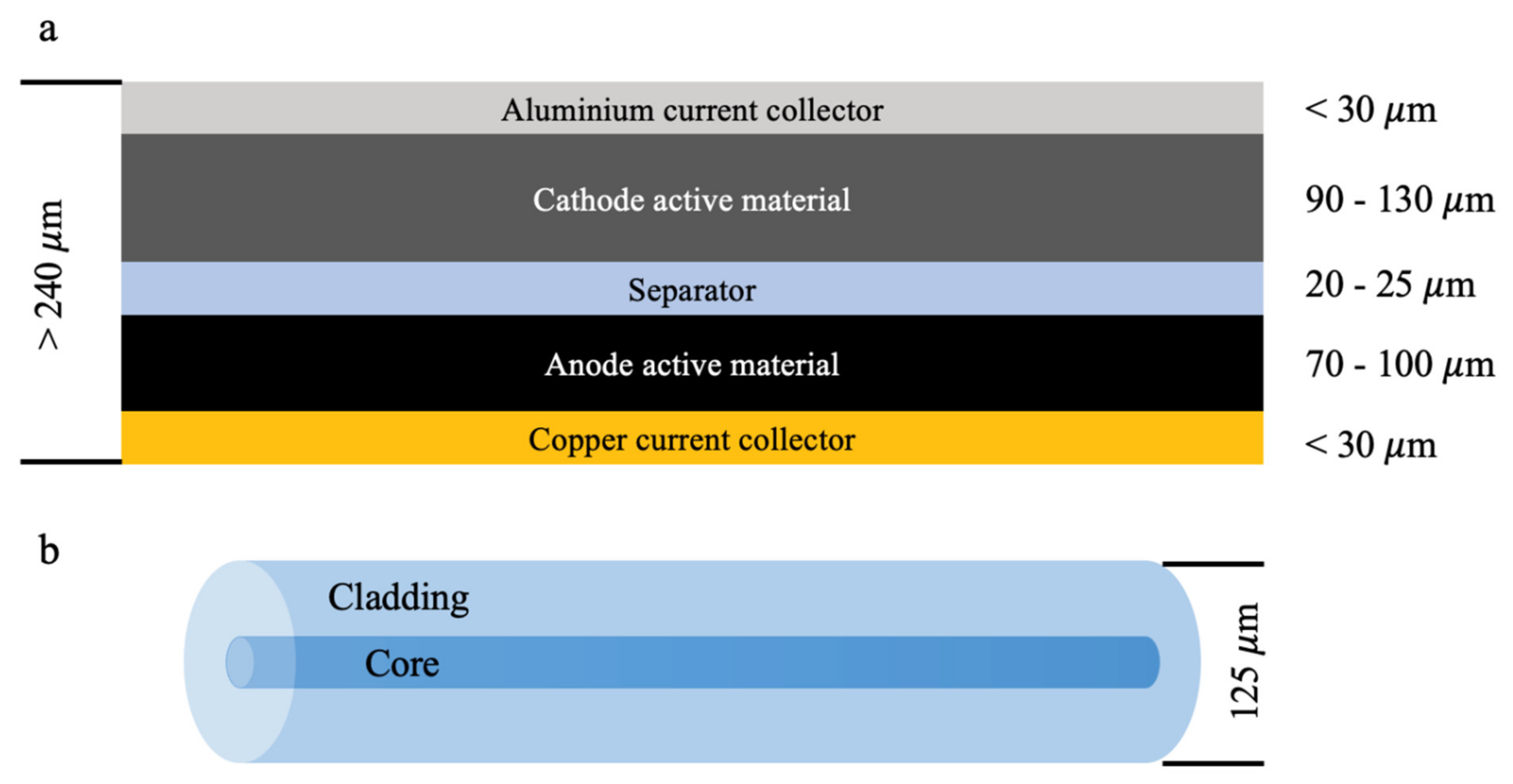
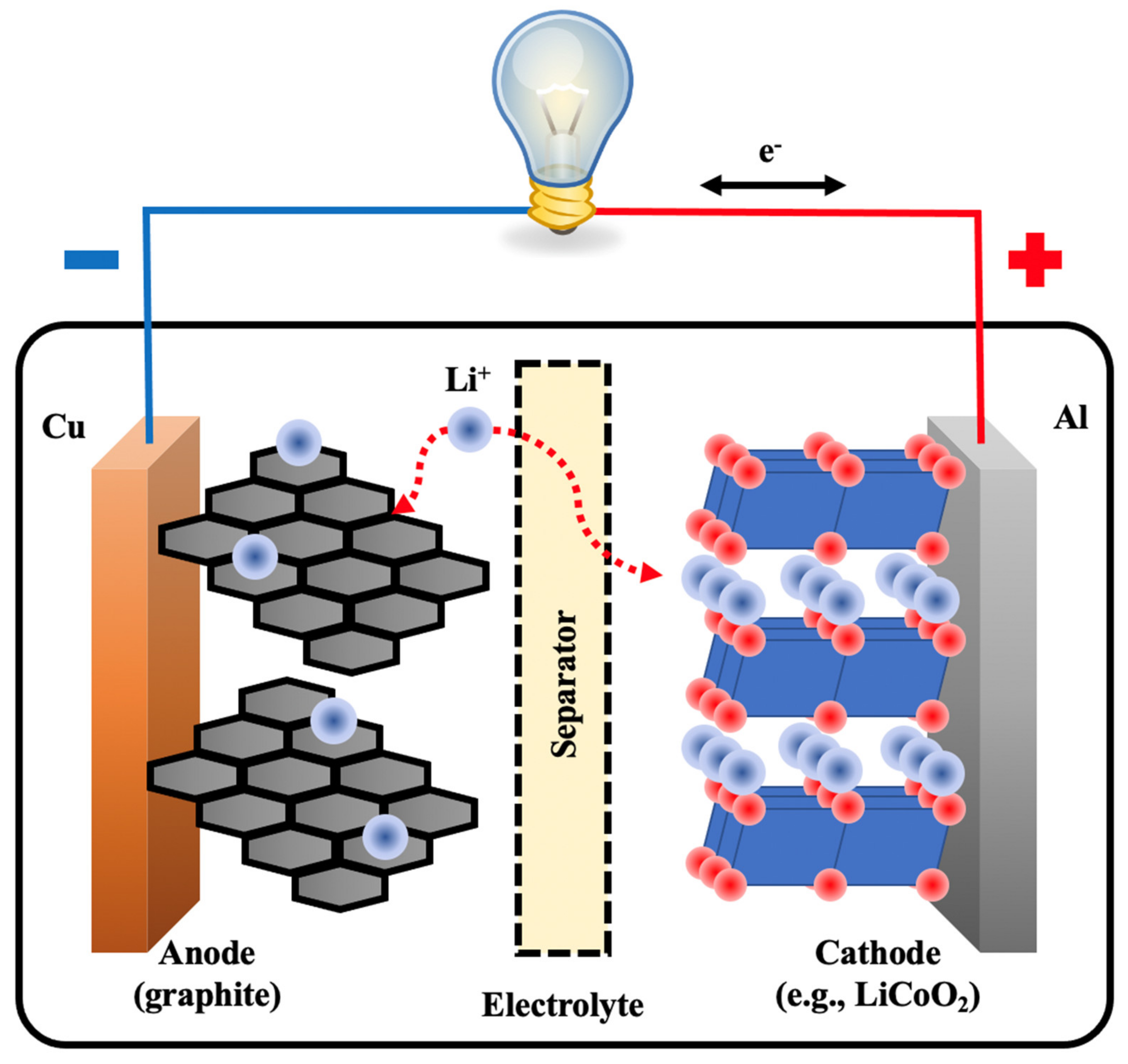
2.1. LiB Structure

Rechargeable LiBs (i.e., secondary batteries) come in a number of shapes and sizes. These are generally in the form of cylindrical, prismatic or pouch cells. The battery electrodes and separator are folded up in such cells to form the battery. Several cells can be within such battery formats. For cylindrical and prismatic cells, the components are rolled up together and placed inside a cylinder or prismatic case. For pouch cells, the sheet stack is enclosed in a pouch. Prismatic and pouch cell batteries provide greater power density for cell phones, laptops, vehicles, or other heavy-duty systems due to the reduced packaging weight.
Secondary LiBs have an anode and a cathode, specified by the discharge phase (Figure 1). The anode is known as the electrode where the oxidation process occurs during discharge (e.g., a carbon-based intercalation anode for a LiB). This ensures that lithium ions provided by the electrolyte salt [e.g., lithium hexafluorophosphate; LiPF6) are deposited in the carbon-based anode during charging. During discharge, Li is oxidized and removed from the anode. The freed lithium ions migrate to the cathode via the electrolyte-separator field. Transition metals in the mixed metal oxides on the cathode are reduced and lower their oxidation number. The first commercial secondary LiB was composed of LiCoO2 when fully discharged, and Li0.45CoO2 when completely charged [28]. Cobalt changes oxidation number in the cathode reduction reaction (from 3.55 to 3). The lithium-cobalt oxide battery is commonly called LCO. When cobalt is partly substituted by nickel and manganese for a combination of nickel, manganese and cobalt, it is called NMC. Moreover, when manganese is replaced by aluminium, it is called NCA, and when the entire mixed metal oxide-lithium mixture is replaced by lithium iron phosphate (LiFePO4), it is called LFP.
LiB architecture is based on the electrode, current collectors and the separator (Figure 2). Usually, the anode current collector (copper) is 30 μm or less, and the active anode carbon layer is 70–100 μm thick [29]. For the cathode, the active coating is usually a mixed metal oxide with an aluminium current collector [29]. The aluminium current collector is also 30 μm or less, and the thickness of the active cathode material is 90 to 130 μm [29]. The separator usually is between 20–25 μm [30,31], and separates the two active electrodes. This configuration for electrodes and separators is conventional for LiBs; however, the thicknesses can vary much more than this in some applications. For in situ and in operando temperature measurements inside a LiB, the sensor must be small, ideally in a range smaller than the separator (i.e., 20–25 μm). Modifying optical sensors to suit this form of geometric restriction will allow measurements that have negligible interaction with the battery’s normal functioning.

2.2. Thermal Issues in LiBs

The thermal balance between produced and dissipated heat together with the heat capacity of the cell influence the internal LiB temperature both at transient and steady state. If the heat cannot be dissipated fast enough, the LiB temperature will rise, leading to increased ageing, failures and unsafe conditions. Defects and misuse during processing and operation may also cause internal and external short-circuits, overcharge, over-discharge or overheating. This can lead to thermal runaway, combustion, and possible LiB explosion [32]. Therefore, LiB ageing is truly the most important parameter, and can be directly influenced by the thermal balance within a cell.
The worst thermal situation is thermal runaway, which can occur under inadequate cooling or abusive usage, leading quickly to gasification, flames, blow-outs or explosions. While thermal runaway can be discussed extensively in six stages [33], a three-stage mechanism [32,34,35,36,37,38,39,40] is more commonly described. Thermal runaway occurs when the cell has reached a temperature at which the self-heating rate is equal to or higher than the heat removal rate. From this point on, reactions within the LiB are exothermic and induce significant temperature changes. The solid electrolyte interphase (SEI) begins decomposing exothermically at temperatures around 90 °C. This results in electrolyte reduction at the exposed anode surface. Around 120 °C, this reaction sequence becomes much more rapid. The separator may also start melting, leading to a sudden voltage drop, further raising the heat generation. Then, the heat generation increases faster due to electrolyte reduction and oxidation at the anode and cathode. Gas can then vent or even release smoke. Further internal heating causes high-rate electrode reactions that induce incredibly rapid temperature changes, eventually contributing to the thermal runaway. This is primarily due to decomposition of the cathode material, creating oxygen gas that interacts exothermically with the organic materials within the LiB [41].
Thermal runaway phenomena rely on different properties such as electrode materials, cell design and electrolyte composition [42]. Experiments have showed that self-heating also relies on the state-of-charge (SoC) [35,43,44,45], as the temperature onset typically declines as SoC increases. As SoC increases, the electrodes become less thermally stable. The voltage displays a sharp decline at temperatures of 125 °C due to separator melting. Thermal stability of the electrodes also depends on the particle size in the electrodes, as the active surface area becomes greater with smaller particles, which creates a larger contact area between the electrode and the electrolyte [46,47]. To avoid risky conditions like thermal runaway, the voltage, current and temperature must be monitored and included in the BMS to take preventative action before thermal runaway occurs. Despite this, BMS cannot always shield LiBs from abusive situations. Additionally, protective sensors that are integrated in or on LiBs and may be damaged before the BMS can take evasive action. Overall, careful design precautions must be taken into account to avoid or stop thermal runaway in a single LiB and the propagation through a full LiB pack. Once a LiB pack is used in an application, it is critical that all LiBs within a module or pack are monitored for performance purposes as well as safety purposes.

3. Thermal Aspects of LiBs

While LiBs have very high coulombic performance [48,49], lithium (de-)intercalation in both electrodes and all related processes do not occur with 100 percent energy efficiency. This property produces irreversible heat while the battery is charged or discharged. The heat generated flows through the materials to the battery surface, dissipating to the surroundings.

3.1. Generation of Heat in LiBs

Due to different internal impedances, battery terminal voltage deviates from the open cell voltage (OCV) at a given SoC [28,50]. This is best known as the battery overpotential ( η b a t t e r y ):
η b a t t e r y = E b a t t e r y E b a t t e r y e q
where E b a t t e r y e q is the electromotive force (EMF) and E b a t t e r y is the voltage at the battery terminals. Different methods can experimentally determine the EMF [51,52,53]. The overpotential is negative during discharge and positive during charging. Similarly, electrode overpotentials (positive and negative) can be defined. Total overpotential is induced by various processes occurring in a LiB, such as charge-transfer reactions at electrode/electrolyte interfaces ( η c h a r g e   t r a n s f e r ) [54], diffusion and migration of Li-ions across the electrolyte ( η e l e c t r o l y t e ) [55], diffusion and migration of Li-ions in the electrodes ( η d i f f u s i o n ) [56] and other ohmic losses ( η o h m ) [57]. The overall battery potential can be expressed as:
η b a t t e r y = η c h a r g e   t r a n s f e r + η e l e c t r o l y t e + η d i f f u s i o n + η o h m
Charge-transfer, diffusion, migration and ohmic losses occur in both the anode and cathode. In order to calculate the irreversible heat production ( Q η ) , the battery overpotential can be multiplied by the current [27,58,59,60,61]:
Q η = η b a t t e r y · I t
or by including the resistance and charge transfer overpotential:
Q η = I t 2 · R b a t t e r y t , T  
Here, I represents the battery current and R is the resistance. It is clear that if the battery current or resistance increases, more irreversible heat is generated. Therefore, to minimize these thermal losses, keeping the battery resistance as low as possible is the key. Generally, these resistances increase with decreasing state-of-health (SoH) during cycling and calendar aging, leading to more heat generation during the battery life [62,63,64].
In addition to the irreversible heat generation source resulting from resistances, there is a reversible heat source due to entropy changes in the chemical reactions [65,66,67]. Entropic heat generation can be either endothermic or exothermic and depends on the electrode reaction direction and the SoC. The entropy change ( Δ S ) of the battery can be derived from enthalpy change ( Δ H ) and free energy change [68,69]. Δ S can be represented after further derivations:
Δ S = n · F · E b a t t e r y e q T ξ , p
where T is the battery temperature, ξ is the progress of the reaction (SoC) and p is the pressure. Generally, entropy change is obtained by potentiometric or calorimetric measurements [70]. Once the entropy change is known, the reversible heat ( Q S ) can be calculated as follows:
Q S = I · T · Δ S n · F
The contribution of the entropic heat can be significant, and therefore it is essential for thermal modelling purposes [59,69,71]. Entropic heat generation or absorption may occur on both electrodes, and its magnitude differs for the various electrode materials. Without the entropic term, the model cannot accurately depict temperature behaviour. Therefore, including the entropic term in the model leads to better modelling accuracy [69].

3.2. Conduction of Heat in LiBs

The generated heat flows through the conductive battery materials. This only happens when temperature differences exist (i.e., thermal gradients are apparent). The corresponding heat flux ( q c o n d u c t i o n ) in isotropic materials can be defined as [72,73,74]:
q c o n d u c t i o n = k · T
where k is the thermal conductivity (can be seen as a function of battery location) and T the temperature gradient. Equation (7) is also known as Fourier’s Heat Conduction Law. The minus-sign infers the thermal conduction from high to low temperatures.

3.3. Dissipation of Heat in LiBs

When a LiB operates in a gas or liquid-filled environment, there is a convective heat exchange between the surface and surroundings. Moreover, emitting infrared radiation cools down the LiB surface. Convective ( Q c o n v e c t i o n ) heat exchange can be shown as follows [27]:
Q c o n v e c t i o n = h · A · T T α
and radiative heat exchange ( Q r a d i a t i o n ) can be shown as follows [27]:
Q r a d i a t i o n = σ · ε · A · T 4 T α 4
where h is the heat transfer coefficient, A , the battery surface area, T , the battery surface temperature, T α , the ambient temperature, σ, the Stefan–Boltzmann constant and ε, the surface material emissivity. The heat transfer coefficient depends on natural or forced convection, location, geometry, surface roughness and the LiB properties. To increase heat transfer from the battery surface to the surrounding environment, different external cooling methods may be applied (e.g., air and liquid cooling). Besides external cooling, which only removes heat from the battery surface, internal cooling can also be used. For internal cooling, the battery integrates either micro-channels or small heat pipes [75,76,77,78]. Internal cooling can be more effective than traditional cooling, as unwanted temperature increases, and thermal gradients are easier to control. Additionally, internal cooling prolongs battery life and is safer. Despite these advantages, internal cooling is much harder to implement as the standard internal battery construction must be significantly changed.

3.4. Balance of Heat in LiBs

Once the generation, conduction and dissipation of heat in a LiB are known, a heat balance equation can be defined to calculate the LiB’s temperature evolution. Considering a uniform temperature, the equation is defined as:
m · C P · d T d t = Q i n Q o u t ,
where m is the LiB’s mass and C P is the LiB’s specific heat capacity. Q i n includes all heat-generating processes:
Q i n = Q η + Q S
Q o u t represents the heat dissipation from the LiB:
Q o u t = Q c o n v e c t i o n + Q r a d i a t i o n
The main advantage of this model is the simplicity to predict and integrate temperature changes into temperature models. However, due to the simplicity of this general thermal model, the assumption that the whole LiB has a uniform temperature presents a weakness. In reality, the temperature varies spatially and must be extended into a two or three-dimensional heat expression. The 3D heat equation is defined as [79]:
ρ · C P · T t = · k · T + q i n
where ρ is the density of the LiB material and the heat-generation density ( q i n ) is now location-dependent (see Equations (6) and (11)). The total heat-generation power Q i n in the heat-balance equation (Equation (10)) can be obtained by integrating q i n over the battery volume ( V ):
Q i n t = V q i n · t ,   x ,   y ,   z · d x · d y · d z
Heat dissipation for each point of the cell surface (outer boundary) is formed as:
n · k · T = h · T T α + σ · ε · T 4 T α 4
where T is the temperature gradient and n is the normal vector (outer) at the boundary. Using this model, three-dimensional thermal gradients can be simulated and validated. Still, these models rely on detailed experiments, as measured overpotentials or resistances are required to calculate heat generation. In addition, LiB predictions can be used in real-life applications, facilitating BMS and TMS with determining states such as SoC and SoH. By using models, the number of sensors can be reduced, saving cost and space.

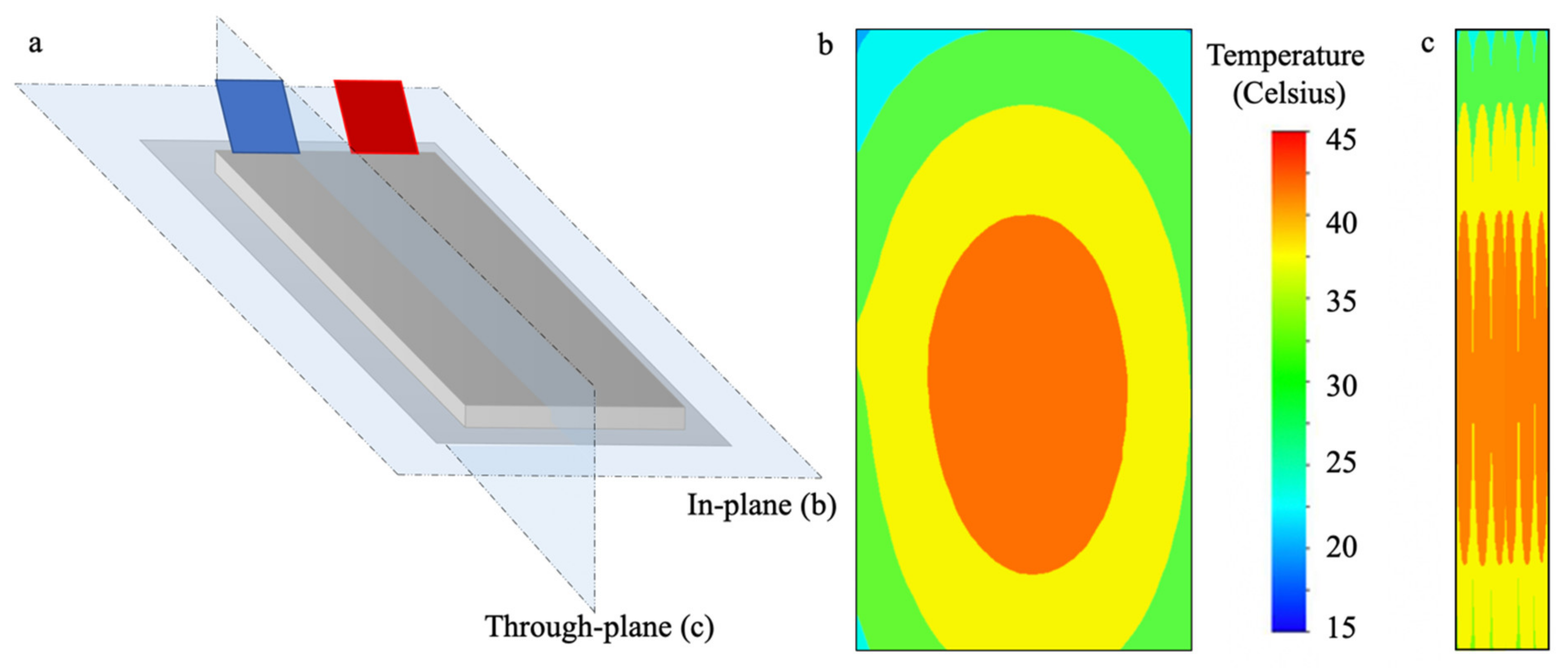
3.5. Gradients of Heat in LiBs

Due to internal heat generation, thermal conduction and heat dissipation in individual LiBs, temperature gradients develop on the module- and pack-level. Temperature gradients in LiB packs is a key issue that cannot be underestimated and can cause serious complications. One such complication is the challenges related to LiB temperature monitoring. Substantial heat is generated internally under extreme conditions like overcharge and over-discharge, high current loads or short-circuiting. Therefore, the surface temperature does not reflect the actual temperature production inside the LiB. With internal monitoring, it can be seen that the LiB core temperature is significantly higher than the surface (Figure 3). It is clear that additional internal temperature monitoring provides more accurate information that will improve LiB performance, SoH and safety.
Other complications resulting from temperature gradients are non-uniform current density, local SoC differences as well as non-uniform and accelerated degradation [80,81]. Temperature gradients cause varying electrochemical impedances; therefore, varying current density distributions [27]. SoC inhomogeneities result from both non-uniform current density distributions and EMF temperature dependence. These effects lead to local aging differences, followed by global LiB aging [59]. Additionally, LiBs perform differently in the presence of a temperature gradient compared to a uniform temperature [82,83]. Besides temperature gradients within individual LiBs, temperature gradients also develop in LiB packs where multiple LiBs are connected. Gradients in LiB packs results in unbalanced charge and discharge currents for LiBs [84,85]. In addition, LiBs that are not closely connected to cooling systems run at higher temperatures.
With low atmospheric temperatures (i.e., low LiB starting temperature) and high C-rates, high temperature increases and high thermal gradients will occur within the LiB due to higher internal resistance [86]. Therefore, stronger cooling is required at high C-rates. Stronger cooling results in lower temperature increases, but can result in higher temperature gradients [5,20,87]. The cooling method employed affects the thermal gradient behaviour (e.g., tab cooling leads to a higher uniformity of the temperature distribution compared to surface cooling [88]; however, lower amounts of heat can be removed through the tabs due to the smaller area). Internal LiB cooling is better at reducing thermal gradients than external cooling [89]; however, internal cooling is much more complicated and increases the mass of the LiB, reducing the specific energy density.
The thermal issues discussed here accentuate the importance of temperature control in LiBs. Fibre Bragg gratings are ideal for in situ temperature measurements, as previously discussed. These are described in the next section, followed by an overview of the relevant literature.

4. Fibre Optic Internal LiB Temperature Monitoring

There are many different methods to measure LiB temperature [27]. These include thermistors [90], thermocouple devices [91], resistance temperature sensors [92], impedance-based temperature measurements [93], Johnson noise thermometry [94], thermal imagery [95], liquid-crystal thermography [96] and estimation with model-based observers [71]. In situ temperature measurements are attractive for safety and control purposes, as LiB core temperatures are usually higher than external temperatures. Moreover, electrochemical inert, corrosion resistant and non-invasive sensors are essential to gaining insight into internal temperatures while avoiding interruptions to the LiB mechanisms. Optical-fibre sensors (e.g., FBGs) are therefore an attractive option, as they are made of chemically inert glass with micrometer dimensions.

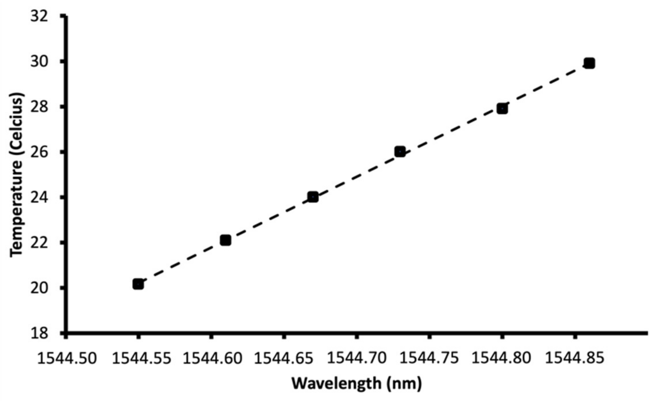
Fibre Bragg Grating Temperature Sensors

The fibre Bragg grating (FBG) sensor is a type of fibre-optic sensor commonly used to measure temperature and strain. The grating exhibits a strong reflectivity at a wavelength (λB), which shifts due to changes in external conditions. The gratings can be inscribed into a photosensitive fibre using UV light, producing permanent periodic changes in the core refractive index [97], (Figure 4).
As a spectrum of light propagates through the fibre, a narrow range of wavelengths are reflected, while the remaining light is transmitted. The centre-wavelength of the reflected signal (Bragg wavelength) is given by:
λ B = 2 · n e f f e c t i v e · Λ
where n e f f e c t i v e is the effective refractive index of the grating and Λ is the period of the index modulation or grating spacing [11,98,99]. A change in n e f f e c t i v e or a difference in Λ (or a combination of both) culminates in a change in the reflected Bragg wavelength. Measuring this wavelength change is the basis for FBG sensors [100]. As a fibre is compressed or extended (i.e., subject to strain), the grating spacing varies, leading to a change in the Bragg wavelength that can be probed with a light source and a spectrometer. Changes in temperature also affect the Bragg wavelength due to the temperature-dependency of the refractive index, known as the thermo-optic effect [101]. The role of thermal expansion is very limited (ca. 5%) and changes in the grating spacing can be neglected (i.e., the thermo-optic effect is the most dominant effect in an FBG) [102]. Figure 5 gives a schematic representation of how the strain and temperature alter the Bragg wavelength.
FBG sensors are becoming increasingly common due to their small scale, light weight, passive design, electromagnetic and radio frequency interference tolerance, high sensitivity and long-term reliability [103,104,105]. Another advantage is that FBG sensors can be multiplexed, meaning multiple FBGs can be inscribed in a single optical fibre making it possible to construct a matrix of temperature sensors in 3D [106]. Additionally, the Bragg wavelength changes with temperature linearly, as shown in Figure 6 [107].
The FBG’s temperature range depends on what materials are used in the construction [108]. Silica is the most typical material used in optical fibres and can endure temperatures between −273 to 1190 °C before softening, yet the gratings within the fibre degrade rapidly above 200 °C [109]. If protective coatings are used, there are additional drawbacks in terms of the temperature window (e.g., acrylate is a standard optical fibre coating which is stable from −40 to 85 °C). Therefore, coatings of polyimide should be used as they have a larger temperature window (−190 to 385 °C). It is possible to obtain accuracies of ±0.2 °C in a temperature range of approximately 20–60 °C [107,110], with a standard temperature sensitivity of 10 pm wavelength shift per °C [99,111].
Although optical FBG sensors have already been investigated in electrochemical systems such as PEM fuel cells [22,112], Yang et al. [8] were the first to investigate FBG sensors on LiBs. Three coin-cell LiBs were used to measure the temperature on all flat surfaces. In addition, the temperature was measured in a cylindrical LiB’s flat and lateral face. FBG sensor calibration showed a linear response in temperature from 0 to 60 °C. These calibration measurements found a typical sensitivity of 10 pm wavelength shift per °C. Following this contribution, research activities with LiB optical FBG sensors increased. Nascimento et al. [23] applied FBG sensors to a 18,650 cylindrical LiB. Two Bragg gratings were used for temperature measurements at two positions on the LiB. An additional fibre was connected along the longitudinal axis to track strain variations. They found that temperature and strain variations were higher at a high C-rate (1.33 C) relative to a low C-rate of 0.25.
Novais et al. [113] continued their study by examining FBG temperature measurements in LiB pouch cells. Two optical fibres with two Bragg gratings were used for internal and external temperature measurement. They also tested the chemical resistance of the fibre with LiPF6. After two weeks of electrolyte storage, only a very small amount of Si was dissolved, suggesting that this form of fibre is not susceptible to the electrolyte in short time windows. They observed an average sensitivity of 8.40 and 10.255 pm wavelength shift per °C for external and internal FBG sensors (in a temperature range of 10 and 35 °C), respectively. Nascimento et al. [114] then compared FBG temperature readings to industrial thermocouples attached on the external surface of the battery. It was found that FBG sensor reaction rate is around 1.2 times faster than the thermocouples used. The discrepancy between FBG peak temperatures and thermocouples was up to 5.7 °C at a C-rate of 8.25. This observation is supported by McTurk et al. [115], allowing unprecedented thermo-electrochemical data from the LiB internal environment. Quick thermal evolutions occur at high C-rates, which thermocouples cannot completely observe due to the slow response time. The faster thermal response of fibre-optic sensors may be attributed to the lower thermal mass, compared to the industrial thermocouples. The thermocouples can be made thinner, but challenges related to the heat-sealing may occur [116]. The optical fibres also have the advantage that the area that the electrode area that is covered by the sensor, and hence blocks the flow of ions, is minimal compared to electrical sensors created on thin-films.
Raghavan et al. [117] and Ganguli et al. [118] embedded FBG sensors for precise internal LiB monitoring status. They showed that seal integrity, power retention and estimated battery life with embedded FBG sensors are highly comparable to batteries without FBG sensors [117]. It has also been demonstrated that batteries with embedded sensors can be incorporated into existing modules. Therefore, they deemed it possible to embed FBG sensors in large-format LiBs as a low-cost, field-deployable internal state monitoring option. They also focused on using internal FBG measurements for tracking SoC and SoH at various temperatures [118]. It was found that SoC can be calculated with an error of less than 2.5% using the strain determined by FBG sensors by measuring the lithiation and delithiation as a function of cathode swelling.
Amietszajew et al. [119] used an FBG sensor to test a commercial, high-energy, 18,650 LiB’s internal temperature. The FBG was placed in an aluminium tube with a fluorinated ethylene propylene heat-shrink, then completely sealed the aluminium tube to protect the FBG sensor from electrical, chemical and mechanical tension. The LiB surface and ambient temperatures were observed using standard thermocouples. They observed that the LiB can be charged 6.7 times faster than the manufacturer stated without violating the electrochemical and thermal protection limits.
Due to the ability of FBG sensors to detect both temperature and strain, it may be beneficial for detection of growth and contraction of the SEI, especially in LiBs containing silicon [120,121,122]. However, it is vital to be able to discriminate between signals due to either temperature or strain within the FBG sensor. Nascimento et al. [123] recently suggested the integration of a FBG and a Fabry–Perot cavity to allow discrimination between temperature and strain. Their findings prove that it is possible to integrate both detection methods within a single fibre and embed this within a LiB to obtained strain and temperature measurements.
To date, there has been limited published measurements for temperatures below 0 °C with FBG temperature sensors in LiBs [118], which is a critical range for operation. Despite this, the possibility to measure low temperatures between −20–0 °C has been shown [124,125]. The use of FBG sensors in LiBs is still in early stages of development, and research and detailed investigations are still required. This is also of particular importance for long-term measurements. It should also be observed whether strain and temperature measurements can be differentiated in LiBs using an FBG and Brillouin scattering sensor system [126], or potentially using tilted FBGs. In addition, it has been observed that FBG sensors can cause damage to cathode and separator material during embedding [127]; therefore, the embedding method for FBGs within a LiB requires further development. This could be through implementation directly into the active material during fabrication, or other components such as the pouch plastic.
Although the characteristics of optical-fibre sensors make them exceptional for internal sensing in LiBs, they also come with certain limitations. The intrinsic cross-sensitivity between temperature and strain requires additional measures to decouple, such as friction-free encapsulation [128] or a second sensor with different sensitivities [123]. Conventional optical fibres are also relatively thick compared to the individual layers in a battery (see Figure 2). This may cause damage to the cathode and separator [127], and thicker stacks are therefore recommended to alleviate the problem [27]. Thin-film based electronic sensors can be made thinner [116], but do not have the beneficial characteristics of an optical fibre. With all internal temperature sensors in complete LiB cells, an additional point of entry is required. This can be challenging and increases the probability of a leak [117], see Figure 7.

5. Conclusions

The thermal behaviour within LiB cells is detrimental to maintaining healthy and safe cell function. Excess heat created during charge/discharge will age cells irreversibly, eventually leading to failure. Traditional thermal measurements of LiBs are conducted on the surface of the cell, which yields limited thermal overview of the internal temperature profile. Additionally, the internal environment of a LiB is chemically and electrically aggressive, meaning that many traditional thermal sensors are not ideal for internal measurement. This review article has discussed the current developments in this field by implementing FBG-based optical fibre sensors into LiB cells. Due to the measurement method, these sensors are ideal for use in LiBs, as they are resistant to chemical degradation and are electrically inert. The use of FBG-based sensors in LiBs is a relatively recent development and still requires further development of the sensor technology to improve their integration into LiB cells. There is still a requirement to develop ideal methods for differentiating between FBG signals from temperature and strain. Although this is possible in a traditional FBG sensor, the size requirements for use in a LiB mean that further development is necessary. Furthermore, the current size of FBG-based sensors is rather thick in terms of the size of a LiB cell, and further size reduction or integration methods must be developed to reduce the interference the sensor may have on the LiB function. As with all physical sensors for internal temperature measurement, an additional point of entry is required, which increases the probability of a leak. Although there are large developments required to perfect the application of FBG-based sensors into LiB cells, these optical fibre sensors have large potential for improving our understanding of thermal distribution within LiBs. This is especially the case with larger pouch cell formats and high charge/discharge rates becoming widely used.

Author Contributions

M.S.W. & L.S. contributed as the first author to summarize the literature. J.J.L. drafted the manuscript. M.S.W., L.S., H.I.M., A.J. & O.S.B. contributed to reviewing the manuscript and highlighting the manuscript. O.S.B. and J.J.L. contributed to the supervising, review, and editing. All authors have read and agreed to the published version of the manuscript.

Funding

This research is funded by The Research Council of Norway, via the research project BattMarine (Project No. 281005), and the research project KeyTechNeVe Chino (Project No. 304213).

Acknowledgments

The authors would like to acknowledge the support from the ENERSENSE research initiative at NTNU, Norway.

Conflicts of Interest

The authors declare no conflict of interest.

References

  1. Opitz, A.; Badami, P.; Shen, L.; Vignarooban, K.; Kannan, A. Can Li-Ion batteries be the panacea for automotive applications? Renew. Sustain. Energy Rev. 2017, 68, 685–692. [Google Scholar] [CrossRef] [Green Version]
  2. Diouf, B.; Pode, R. Potential of lithium-ion batteries in renewable energy. Renew. Energy 2015, 76, 375–380. [Google Scholar] [CrossRef]
  3. Jaiswal, A. Lithium-ion battery based renewable energy solution for off-grid electricity: A techno-economic analysis. Renew. Sustain. Energy Rev. 2017, 72, 922–934. [Google Scholar] [CrossRef]
  4. Chen, J.; Cheng, F. Combination of Lightweight Elements and Nanostructured Materials for Batteries. Accounts Chem. Res. 2009, 42, 713–723. [Google Scholar] [CrossRef] [PubMed]
  5. Kizilel, R.; Sabbah, R.; Selman, R.; Al-Hallaj, S. An Alternative Cooling System to Enhance the Safety for High Power Li-Ion Battery Packs. ECS Meet. Abstr. 2008, 194, 1105–1112. [Google Scholar] [CrossRef]
  6. Sethuraman, V.; Van Winkle, N.; Abraham, D.; Bower, A.; Guduru, P. Real-time stress measurements in lithium-ion battery negative-electrodes. J. Power Sources 2012, 206, 334–342. [Google Scholar] [CrossRef] [Green Version]
  7. Kim, U.S.; Yi, J.; Shin, C.B.; Han, T.; Park, S. Modelling the thermal behaviour of a lithium-ion battery during charge. J. Power Sources 2011, 196, 5115–5121. [Google Scholar] [CrossRef]
  8. Yang, G.; Leitão, C.; Li, Y.; Pinto, J.; Jiang, X. Real-time temperature measurement with fiber Bragg sensors in lithium batteries for safety usage. Measurement 2013, 46, 3166–3172. [Google Scholar] [CrossRef]
  9. Spitthoff, L.; Lamb, J.J.; Pollet, B.G.; Burheim, O.S. Lifetime Expectancy of Lithium-Ion Batteries. In Micro-Optics and Energy; Springer: Berlin, Germany, 2020; pp. 157–180. [Google Scholar]
  10. Spitthoff, L.; Øyre, E.S.; Muri, H.I.; Wahl, M.; Gunnarshaug, A.F.; Pollet, B.G.; Lamb, J.J.; Burheim, O.S. Thermal Management of Lithium-Ion Batteries. In Micro-Optics and Energy; Springer: Berlin, Germany, 2020; pp. 183–194. [Google Scholar]
  11. Wahl, M.S.; Muri, H.I.; Snilsberg, R.K.; Lamb, J.J.; Hjelme, D.R. Temperature and Humidity Measurements. In Micro-Optics and Energy; Springer: Berlin, Germany, 2020; pp. 31–43. [Google Scholar]
  12. Spotnitz, R.M.; Weaver, J.; Yeduvaka, G.; Doughty, D.; Roth, E. Simulation of abuse tolerance of lithium-ion battery packs. J. Power Sources 2007, 163, 1080–1086. [Google Scholar] [CrossRef]
  13. Röder, P.; Stiaszny, B.; Ziegler, J.C.; Baba, N.; Lagaly, P.; Wiemhöfer, H.-D. The impact of calendar aging on the thermal stability of a LiMn2O4–Li (Ni1/3Mn1/3Co1/3) O2/graphite lithium-ion cell. J. Power Sources 2014, 268, 315–325. [Google Scholar] [CrossRef]
  14. Lu, L.; Han, X.; Li, J.; Hua, J.; Ouyang, M. A review on the key issues for lithium-ion battery management in electric vehicles. J. Power Sources 2013, 226, 272–288. [Google Scholar] [CrossRef]
  15. Spitthoff, L.; Gunnarshaug, A.F.; Bedeaux, D.; Burheim, O.; Kjelstrup, S. Peltier effects in lithium-ion battery modeling. J. Chem. Phys. 2021, 154, 114705. [Google Scholar] [CrossRef]
  16. Fan, J.; Tan, S. Studies on Charging Lithium-Ion Cells at Low Temperatures. J. Electrochem. Soc. 2006, 153, A1081–A1092. [Google Scholar] [CrossRef]
  17. Huang, C.-K.; Sakamoto, J.S.; Wolfenstine, J.; Surampudi, S. The Limits of Low-Temperature Performance of Li-Ion Cells. J. Electrochem. Soc. 2000, 147, 2893. [Google Scholar] [CrossRef] [Green Version]
  18. Kim, U.S.; Shin, C.B.; Kim, C.-S. Effect of electrode configuration on the thermal behavior of a lithium-polymer battery. J. Power Sources 2008, 180, 909–916. [Google Scholar] [CrossRef]
  19. Richardson, R.R.; Ireland, P.T.; Howey, D.A. Battery internal temperature estimation by combined impedance and surface temperature measurement. J. Power Sources 2014, 265, 254–261. [Google Scholar] [CrossRef]
  20. Veneri, O. Technologies and applications for smart charging of electric and plug-in hybrid vehicles. In Technologies and Applications for Smart Charging of Electric and Plug-In Hybrid Vehicles; Springer: Berlin, Germany, 2017; pp. 1–307. [Google Scholar]
  21. Lamb, J.J.; Burheim, O.S.; Pollet, B.G. Hydrogen Fuel Cells and Water Electrolysers. In Micro-Optics and Energy; Springer: Berlin, Germany, 2020; pp. 61–71. [Google Scholar]
  22. David, N.A.; Wild, P.M.; Hu, J.; Djilali, N. In-fibre Bragg grating sensors for distributed temperature measurement in a polymer electrolyte membrane fuel cell. J. Power Sources 2009, 192, 376–380. [Google Scholar] [CrossRef]
  23. Nascimento, M.; Novais, S.; Leitão, C.; Domingues, M.D.F.F.; Alberto, N.; Antunes, P.; Pinto, J.L. Lithium batteries temperature and strain fiber monitoring. In Proceedings of the 24th International Conference on Optical Fibre Sensors, Curitiba, Brazil, 28 September–2 October 2015. [Google Scholar]
  24. Sommer, L.W.; Raghavan, A.; Kiesel, P.; Saha, B.; Schwartz, J.; Lochbaum, A.; Ganguli, A.; Bae, C.-J.; Alamgir, M. Monitoring of intercalation stages in lithium-ion cells over charge-discharge cycles with fiber optic sensors. J. Electrochem. Soc. 2015, 162, A2664–A2669. [Google Scholar] [CrossRef]
  25. Sommer, L.W.; Kiesel, P.; Ganguli, A.; Lochbaum, A.; Saha, B.; Schwartz, J.; Bae, C.-J.; Alamgir, M.; Raghavan, A. Fast and slow ion diffusion processes in lithium ion pouch cells during cycling observed with fiber optic strain sensors. J. Power Sources 2015, 296, 46–52. [Google Scholar] [CrossRef] [Green Version]
  26. Bae, C.-J.; Manandhar, A.; Kiesel, P.; Raghavan, A. Monitoring the Strain Evolution of Lithium-Ion Battery Electrodes using an Optical Fiber Bragg Grating Sensor. Energy Technol. 2016, 4, 851–855. [Google Scholar] [CrossRef]
  27. Raijmakers, L.; Danilov, D.; Eichel, R.-A.; Notten, P. A review on various temperature-indication methods for Li-ion batteries. Appl. Energy 2019, 240, 918–945. [Google Scholar] [CrossRef]
  28. Goodenough, J.B.; Park, K.-S. The Li-Ion Rechargeable Battery: A Perspective. J. Am. Chem. Soc. 2013, 135, 1167–1176. [Google Scholar] [CrossRef]
  29. Richter, F.; Vie, P.J.; Kjelstrup, S.; Burheim, O.S. Measurements of ageing and thermal conductivity in a secondary NMC-hard carbon Li-ion battery and the impact on internal temperature profiles. Electrochim. Acta 2017, 250, 228–237. [Google Scholar] [CrossRef]
  30. Richter, F.; Kjelstrup, S.; Vie, P.J.; Burheim, O.S. Thermal conductivity and internal temperature profiles of Li-ion secondary batteries. J. Power Sources 2017, 359, 592–600. [Google Scholar] [CrossRef] [Green Version]
  31. Burheim, O.S.; Onsrud, M.A.; Pharoah, J.G.; Vullum-Bruer, F.; Vie, P.J.S. Thermal Conductivity, Heat Sources and Temperature Profiles of Li-Ion Secondary Batteries. ECS Meet. Abstr. 2013, 58, 145–171. [Google Scholar] [CrossRef]
  32. Lisbona, D.; Snee, T. A review of hazards associated with primary lithium and lithium-ion batteries. Process. Saf. Environ. Prot. 2011, 89, 434–442. [Google Scholar] [CrossRef]
  33. Feng, X.; Fang, M.; He, X.; Ouyang, M.; Lu, L.; Wang, H.; Zhang, M. Thermal runaway features of large format prismatic lithium ion battery using extended volume accelerating rate calorimetry. J. Power Sources 2014, 255, 294–301. [Google Scholar] [CrossRef]
  34. Bandhauer, T.M.; Garimella, S.; Fuller, T.F. A Critical Review of Thermal Issues in Lithium-Ion Batteries. J. Electrochem. Soc. 2011, 158, R1. [Google Scholar] [CrossRef]
  35. Doughty, D.H.; Roth, E.P. A General Discussion of Li Ion Battery Safety. Electrochem. Soc. Interface 2012, 21, 37–44. [Google Scholar] [CrossRef] [Green Version]
  36. Wen, J.; Yu, Y.; Chen, C. A Review on Lithium-Ion Batteries Safety Issues: Existing Problems and Possible Solutions. Mater. Express 2012, 2, 197–212. [Google Scholar] [CrossRef]
  37. Abraham, D.; Roth, E.; Kostecki, R.; McCarthy, K.; MacLaren, S.; Doughty, D. Diagnostic examination of thermally abused high-power lithium-ion cells. J. Power Sources 2006, 161, 648–657. [Google Scholar] [CrossRef]
  38. Roth, E.P. Abuse response of 18650 Li-ion cells with different cathodes using EC: EMC/LiPF6 and EC: PC: DMC/LiPF6 electrolytes. ECS Trans. 2008, 11, 19. [Google Scholar] [CrossRef]
  39. Spotnitz, R.; Franklin, J. Abuse behavior of high-power, lithium-ion cells. J. Power Sources 2003, 113, 81–100. [Google Scholar] [CrossRef]
  40. Dahn, J.R.; Fuller, E.W.; Obrovac, M.; Von Sacken, U. Thermal stability of LixCoO2, LixNiO2 and λ-MnO2 and consequences for the safety of Li-ion cells. Solid State Ionics 1994, 69, 265–270. [Google Scholar] [CrossRef]
  41. Arai, H.; Tsuda, M.; Saito, K.; Hayashi, M.; Sakurai, Y. Thermal Reactions Between Delithiated Lithium Nickelate and Electrolyte Solutions. J. Electrochem. Soc. 2002, 149, A401–A406. [Google Scholar] [CrossRef]
  42. Wang, Q.; Ping, P.; Zhao, X.; Chu, G.; Sun, J.; Chen, C. Thermal runaway caused fire and explosion of lithium ion battery. J. Power Sources 2012, 208, 210–224. [Google Scholar] [CrossRef]
  43. Roth, E.; Doughty, D. Thermal abuse performance of high-power 18650 Li-ion cells. J. Power Sources 2004, 128, 308–318. [Google Scholar] [CrossRef]
  44. Al Hallaj, S.; Maleki, H.; Hong, J.-S.; Selman, J.R. Thermal modeling and design considerations of lithium-ion batteries. J. Power Sources 1999, 83, 1–8. [Google Scholar] [CrossRef]
  45. Mendoza-Hernandez, O.S.; Ishikawa, H.; Nishikawa, Y.; Maruyama, Y.; Umeda, M. Cathode material comparison of thermal runaway behavior of Li-ion cells at different state of charges including over charge. J. Power Sources 2015, 280, 499–504. [Google Scholar] [CrossRef]
  46. El Khakani, S.; Rochefort, D.; MacNeil, D.D. ARC study of LiFePO4 with different morphologies prepared via three synthetic routes. J. Electrochem. Soc. 2016, 163, A1311–A1316. [Google Scholar] [CrossRef]
  47. Jiang, J.; Dahn, J. Effects of particle size and electrolyte salt on the thermal stability of Li 0.5 CoO2. Electrochim. Acta 2004, 49, 2661–2666. [Google Scholar] [CrossRef]
  48. Scrosati, B.; Garche, J. Lithium batteries: Status, prospects and future. J. Power Sources 2010, 195, 2419–2430. [Google Scholar] [CrossRef]
  49. Nitta, N.; Wu, F.; Lee, J.T.; Yushin, G. Li-ion battery materials: Present and future. Mater. Today 2015, 18, 252–264. [Google Scholar] [CrossRef]
  50. Kasnatscheew, J.; Rodehorst, U.; Streipert, B.; Wiemers-Meyer, S.; Jakelski, R.; Wagner, R.; Laskovic, I.C.; Winter, M. Learning from overpotentials in lithium ion batteries: A case study on the LiNi1/3Co1/3Mn1/3O2 (NCM) cathode. J. Electrochem. Soc. 2016, 163, A2943. [Google Scholar] [CrossRef]
  51. Notten, P.; Bergveld, H.; Kruijt, W. Battery Management Systems: Design by Modeling; Kluwer Academic Publisher Norwell: Norwell, MA, USA, 2002. [Google Scholar]
  52. Pop, V.; Bergveld, H.J.; Veld, J.H.G.O.H.; Regtien, P.P.L.; Danilov, D.; Notten, P.H.L. Modeling Battery Behavior for Accurate State-of-Charge Indication. J. Electrochem. Soc. 2006, 153, A2013–A2022. [Google Scholar] [CrossRef] [Green Version]
  53. Danilov, D.D.; Niessen, R.R.; Notten, P.P. Modeling All-Solid-State Li-Ion Batteries. J. Electrochem. Soc. 2011, 158, A215–A222. [Google Scholar] [CrossRef] [Green Version]
  54. Heubner, C.; Schneider, M.; Lämmel, C.; Michaelis, A. Local Heat Generation in a Single Stack Lithium Ion Battery Cell. Electrochim. Acta 2015, 186, 404–412. [Google Scholar] [CrossRef]
  55. Danilov, D.; Notten, P. Mathematical Modeling of the Ionic Transport Inside Electrolytes of Li-Ion Batteries. ECS Meet. Abstr. 2007, 53, 5569–5578. [Google Scholar] [CrossRef]
  56. Grazioli, D.; Magri, M.; Salvadori, A. Computational modeling of Li-ion batteries. Comput. Mech. 2016, 58, 889–909. [Google Scholar] [CrossRef] [Green Version]
  57. Andre, D.; Meiler, M.; Steiner, K.; Wimmer, C.; Soczka-Guth, T.; Sauer, D.U. Characterization of high-power lithium-ion batteries by electrochemical impedance spectroscopy. I. Experimental investigation. J. Power Sources 2011, 196, 5334–5341. [Google Scholar] [CrossRef]
  58. Schuster, E.; Ziebert, C.; Melcher, A.; Rohde, M.; Seifert, H.J. Thermal behavior and electrochemical heat generation in a commercial 40 Ah lithium ion pouch cell. J. Power Sources 2015, 286, 580–589. [Google Scholar] [CrossRef]
  59. De Vita, A.; Maheshwari, A.; Destro, M.; Santarelli, M.; Carello, M. Transient thermal analysis of a lithium-ion battery pack comparing different cooling solutions for automotive applications. Appl. Energy 2017, 206, 101–112. [Google Scholar] [CrossRef]
  60. Williford, R.E.; Viswanathan, V.V.; Zhang, J.-G. Effects of entropy changes in anodes and cathodes on the thermal behavior of lithium ion batteries. J. Power Sources 2009, 189, 101–107. [Google Scholar] [CrossRef]
  61. Yang, X.-G.; Zhang, G.; Wang, C.-Y. Computational design and refinement of self-heating lithium ion batteries. J. Power Sources 2016, 328, 203–211. [Google Scholar] [CrossRef]
  62. Ecker, M.; Gerschler, J.B.; Vogel, J.; Käbitz, S.; Hust, F.; Dechent, P.; Sauer, D.U. Development of a lifetime prediction model for lithium-ion batteries based on extended accelerated aging test data. J. Power Sources 2012, 215, 248–257. [Google Scholar] [CrossRef]
  63. Eddahech, A.; Briat, O.; Vinassa, J.-M. Performance comparison of four lithium–ion battery technologies under calendar aging. Energy 2015, 84, 542–550. [Google Scholar] [CrossRef]
  64. Schmitt, J.; Maheshwari, A.; Heck, M.; Lux, S.; Vetter, M. Impedance change and capacity fade of lithium nickel manganese cobalt oxide-based batteries during calendar aging. J. Power Sources 2017, 353, 183–194. [Google Scholar] [CrossRef]
  65. Rao, L.; Newman, J. Heat-Generation Rate and General Energy Balance for Insertion Battery Systems. J. Electrochem. Soc. 1997, 144, 2697–2704. [Google Scholar] [CrossRef]
  66. Guo, M.; Sikha, G.; White, R.E. Single-particle model for a lithium-ion cell: Thermal behavior. J. Electrochem. Soc. 2010, 158, A122. [Google Scholar] [CrossRef]
  67. Bernardi, D.M.; Pawlikowski, E.M.; Newman, J. A General Energy Balance for Battery Systems. J. Electrochem. Soc. 1985, 132, 5–12. [Google Scholar] [CrossRef] [Green Version]
  68. Gibbard, H.F. Thermal Properties of Battery Systems. J. Electrochem. Soc. 1978, 125, 353–358. [Google Scholar] [CrossRef]
  69. Rad, M.S.; Danilov, D.; Baghalha, M.; Kazemeini, M.; Notten, P. Adaptive thermal modeling of Li-ion batteries. Electrochim. Acta 2013, 102, 183–195. [Google Scholar] [CrossRef]
  70. Zhang, X.-F.; Zhao, Y.; Patel, Y.; Zhang, T.; Liu, W.-M.; Chen, M.; Offer, G.J.; Yan, Y. Potentiometric measurement of entropy change for lithium batteries. Phys. Chem. Chem. Phys. 2017, 19, 9833–9842. [Google Scholar] [CrossRef]
  71. Thomas, K.E.; Newman, J. Thermal Modeling of Porous Insertion Electrodes. J. Electrochem. Soc. 2003, 150, A176–A192. [Google Scholar] [CrossRef]
  72. Lienhard, J.H. A Heat Transfer Textbook; Courier Corporation: North Chelmsford, MA, USA, 2011. [Google Scholar]
  73. Incropera, F.P. Fundamentals of Heat and Mass Transfer; Editorial Félix Varela: Havana, Cuba, 2010. [Google Scholar]
  74. Bejan, A.; Kraus, A.D. Heat Transfer Handbook; John Wiley & Sons: Hoboken, NJ, USA, 2003; Volume 1. [Google Scholar]
  75. Shah, K.; McKee, C.; Chalise, D.; Jain, A. Experimental and numerical investigation of core cooling of Li-ion cells using heat pipes. Energy 2016, 113, 852–860. [Google Scholar] [CrossRef] [Green Version]
  76. Anthony, D.; Wong, D.; Wetz, D.; Jain, A. Improved Thermal Performance of a Li-Ion Cell through Heat Pipe Insertion. J. Electrochem. Soc. 2017, 164, A961–A967. [Google Scholar] [CrossRef]
  77. Bandhauer, T.M.; Garimella, S. Passive, internal thermal management system for batteries using microscale liquid–vapor phase change. Appl. Therm. Eng. 2013, 61, 756–769. [Google Scholar] [CrossRef]
  78. Mohammadian, S.K.; He, Y.-L.; Zhang, Y. Internal cooling of a lithium-ion battery using electrolyte as coolant through microchannels embedded inside the electrodes. J. Power Sources 2015, 293, 458–466. [Google Scholar] [CrossRef]
  79. Hahn, D.W.; Özişik, M.N. Heat Conduction; Wiley: Hoboken, NJ, USA, 2012. [Google Scholar]
  80. Fleckenstein, M.; Bohlen, O.; Roscher, M.A.; Bäker, B. Current density and state of charge inhomogeneities in Li-ion battery cells with LiFePO4 as cathode material due to temperature gradients. J. Power Sources 2011, 196, 4769–4778. [Google Scholar] [CrossRef]
  81. Cavalheiro, G.M.; Iriyama, T.; Nelson, G.J.; Huang, S.; Zhang, G. Effects of Nonuniform Temperature Distribution on Degradation of Lithium-Ion Batteries. J. Electrochem. Energy Convers. Storage 2020, 17, 1–16. [Google Scholar] [CrossRef]
  82. Waldmann, T.; Bisle, G.; Hogg, B.-I.; Stumpp, S.; Danzer, M.A.; Kasper, M.; Axmann, P.; Wohlfahrt-Mehrens, M. Influence of Cell Design on Temperatures and Temperature Gradients in Lithium-Ion Cells: An in Operando Study. J. Electrochem. Soc. 2015, 162, A921–A927. [Google Scholar] [CrossRef]
  83. Troxler, Y.; Wu, B.; Marinescu, M.; Yufit, V.; Patel, Y.; Marquis, A.J.; Brandon, N.P.; Offer, G. The effect of thermal gradients on the performance of lithium-ion batteries. J. Power Sources 2014, 247, 1018–1025. [Google Scholar] [CrossRef]
  84. Yang, N.; Zhang, X.; Shang, B.; Li, G. Unbalanced discharging and aging due to temperature differences among the cells in a lithium-ion battery pack with parallel combination. J. Power Sources 2016, 306, 733–741. [Google Scholar] [CrossRef]
  85. Shi, W.; Hu, X.; Jin, C.; Jiang, J.; Zhang, Y.; Yip, T. Effects of imbalanced currents on large-format LiFePO4 /graphite batteries systems connected in parallel. J. Power Sources 2016, 313, 198–204. [Google Scholar] [CrossRef]
  86. Zhang, X. Thermal analysis of a cylindrical lithium-ion battery. Electrochim. Acta 2011, 56, 1246–1255. [Google Scholar] [CrossRef]
  87. Zhang, G.; Cao, L.; Ge, S.; Wang, C.-Y.; Shaffer, C.E.; Rahn, C.D. In Situ Measurement of Radial Temperature Distributions in Cylindrical Li-Ion Cells. J. Electrochem. Soc. 2014, 161, A1499–A1507. [Google Scholar] [CrossRef] [Green Version]
  88. Hunt, I.A.; Zhao, Y.; Patel, Y.; Offer, J. Surface Cooling Causes Accelerated Degradation Compared to Tab Cooling for Lithium-Ion Pouch Cells. J. Electrochem. Soc. 2016, 163, A1846–A1852. [Google Scholar] [CrossRef] [Green Version]
  89. Worwood, D.; Kellner, Q.; Wojtala, M.; Widanage, W.; McGlen, R.; Greenwood, D.; Marco, J. A new approach to the internal thermal management of cylindrical battery cells for automotive applications. J. Power Sources 2017, 346, 151–166. [Google Scholar] [CrossRef]
  90. Christensen, J.; Cook, D.; Albertus, P. An efficient parallelizable 3D thermoelectrochemical model of a Li-Ion cell. J. Electrochem. Soc. 2013, 160, A2258–A2267. [Google Scholar] [CrossRef]
  91. Mutyala, M.S.K.; Zhao, J.; Li, J.; Pan, H.; Yuan, C.; Li, X. In-situ temperature measurement in lithium ion battery by transferable flexible thin film thermocouples. J. Power Sources 2014, 260, 43–49. [Google Scholar] [CrossRef]
  92. Wang, P.; Zhang, X.; Yang, L.; Zhang, X.; Yang, M.; Chen, H.; Fang, D. Real-time monitoring of internal temperature evolution of the lithium-ion coin cell battery during the charge and discharge process. Extreme Mech. Lett. 2016, 9, 459–466. [Google Scholar] [CrossRef]
  93. Schmidt, J.P.; Arnold, S.; Loges, A.; Werner, D.; Wetzel, T.; Ivers-Tiffée, E. Measurement of the internal cell temperature via impedance: Evaluation and application of a new method. J. Power Sources 2013, 243, 110–117. [Google Scholar] [CrossRef]
  94. Liu, X.; Zheng, C.; Liu, C.; Pong, P.W.T. Experimental Investigation of a Johnson Noise Thermometry Using GMR Sensor for Electric Vehicle Applications. IEEE Sensors J. 2018, 18, 3098–3107. [Google Scholar] [CrossRef]
  95. Bahiraei, F.; Ghalkhani, M.; Fartaj, A.; Nazri, G.-A. A pseudo 3D electrochemical-thermal modeling and analysis of a lithium-ion battery for electric vehicle thermal management applications. Appl. Therm. Eng. 2017, 125, 904–918. [Google Scholar] [CrossRef]
  96. Giuliano, M.R.; Advani, S.G.; Prasad, A.K. Thermal analysis and management of lithium–titanate batteries. J. Power Sources 2011, 196, 6517–6524. [Google Scholar] [CrossRef]
  97. Hill, K.; Meltz, G. Fiber Bragg grating technology fundamentals and overview. J. Light. Technol. 1997, 15, 1263–1276. [Google Scholar] [CrossRef] [Green Version]
  98. Wahl, M.S.; Lamb, J.J.; Muri, H.I.; Snilsberg, R.K.; Hjelme, D.R. Light Properties and Sensors. In Micro-Optics and Energy; Springer: Berlin, Germany, 2020; pp. 9–27. [Google Scholar]
  99. Rao, Y.-J. In-fibre Bragg grating sensors. Meas. Sci. Technol. 1997, 8, 355–375. [Google Scholar] [CrossRef]
  100. Juelich, F.; Roths, J. OP2—Determination of the Effective Refractive Index of Various Single Mode Fibres for Fibre Bragg Grating Sensor Applications. In Proceedings of the OPTO 2009 & IRS2, Nürnberg, Germany, 26–28 May 2009; pp. 119–124. [Google Scholar]
  101. Komma, J.; Schwarz, E.C.; Hofmann, O.G.; Heinert, D.; Nawrodt, R. Thermo-optic coefficient of silicon at 1550 nm and cryogenic temperatures. Appl. Phys. Lett. 2012, 101, 041905. [Google Scholar] [CrossRef] [Green Version]
  102. Kersey, A.D.; Davis, M.A.; Patrick, H.J.; Leblanc, M.; Koo, K.P.; Askins, C.G.; Putnam, M.A.; Friebele, E.J. Fiber grating sensors. J. Light. Technol. 1997, 15, 1442–1463. [Google Scholar] [CrossRef] [Green Version]
  103. Morante, M. Fiber Bragg Grating Sensors for Harsh Environments. Master’s Thesis, University of Pisa, Pisa, Italy, 2018. [Google Scholar]
  104. Mihailov, S.J. Fiber Bragg Grating Sensors for Harsh Environments. Sensors 2012, 12, 1898–1918. [Google Scholar] [CrossRef] [PubMed]
  105. Fleming, J.; Amietszajew, T.; McTurk, E.; Towers, D.P.; Greenwood, D.; Bhagat, R. Development and evaluation of in-situ instrumentation for cylindrical Li-ion cells using fibre optic sensors. HardwareX 2018, 3, 100–109. [Google Scholar] [CrossRef]
  106. Vergori, E.; Yu, Y. Monitoring of Li-ion cells with distributed fibre optic sensors. Procedia Struct. Integr. 2019, 24, 233–239. [Google Scholar] [CrossRef]
  107. Du, W.-C.; Tao, X.-M.; Tam, H.-Y. Fiber Bragg grating cavity sensor for simultaneous measurement of strain and temperature. IEEE Photon. Technol. Lett. 1999, 11, 105–107. [Google Scholar] [CrossRef] [Green Version]
  108. Black, R.J.; Moslehi, B. Advanced end-to-end fiber optic sensing systems for demanding environments. In Nanophotonics and Macrophotonics for Space Environments IV; International Society for Optics and Photonics: Bellingham, WA, USA, 2010; p. 78170L. [Google Scholar]
  109. Erdogan, T.; Mizrahi, V.; Lemaire, P.J.; Monroe, D. Decay of ultraviolet-induced fiber Bragg gratings. J. Appl. Phys. 1994, 76, 73–80. [Google Scholar] [CrossRef]
  110. Rao, Y.-J.; Webb, D.; Jackson, D.A.; Zhang, L.; Bennion, I. In-fiber Bragg-grating temperature sensor system for medical applications. J. Light. Technol. 1997, 15, 779–785. [Google Scholar] [CrossRef]
  111. Othonos, A. Fiber Bragg gratings. Rev. Sci. Instrum. 1997, 68, 4309–4341. [Google Scholar] [CrossRef]
  112. David, N.A.; Wild, P.M.; Jensen, J.; Navessin, T.; Djilali, N. Simultaneous in situ measurement of temperature and relative humidity in a PEMFC using optical fiber sensors. J. Electrochem. Soc. 2010, 157, B1173–B1179. [Google Scholar] [CrossRef] [Green Version]
  113. Novais, S.; Nascimento, M.; Grande, L.; Domingues, M.F.; Antunes, P.; Alberto, N.; Leitão, C.; Oliveira, R.; Koch, S.; Kim, G.T.; et al. Internal and External Temperature Monitoring of a Li-Ion Battery with Fiber Bragg Grating Sensors. Sensors 2016, 16, 1394. [Google Scholar] [CrossRef] [Green Version]
  114. Nascimento, M.; Ferreira, M.S.; Pinto, J. Real time thermal monitoring of lithium batteries with fiber sensors and thermocouples: A comparative study. Measurement 2017, 111, 260–263. [Google Scholar] [CrossRef]
  115. McTurk, E.; Amietszajew, T.; Fleming, J.; Bhagat, R. Thermo-electrochemical instrumentation of cylindrical Li-ion cells. J. Power Sources 2018, 379, 309–316. [Google Scholar] [CrossRef]
  116. Martiny, N.; Rheinfeld, A.; Geder, J.; Wang, Y.; Kraus, W.; Jossen, A. Development of an All Kapton-Based Thin-Film Thermocouple Matrix for In Situ Temperature Measurement in a Lithium Ion Pouch Cell. IEEE Sensors J. 2014, 14, 3377–3384. [Google Scholar] [CrossRef]
  117. Raghavan, A.; Kiesel, P.; Sommer, L.W.; Schwartz, J.; Lochbaum, A.; Hegyi, A.; Schuh, A.; Arakaki, K.; Saha, B.; Ganguli, A.; et al. Embedded fiber-optic sensing for accurate internal monitoring of cell state in advanced battery management systems part 1: Cell embedding method and performance. J. Power Sources 2017, 341, 466–473. [Google Scholar] [CrossRef] [Green Version]
  118. Ganguli, A.; Saha, B.; Raghavan, A.; Kiesel, P.; Arakaki, K.; Schuh, A.; Schwartz, J.; Hegyi, A.; Sommer, L.W.; Lochbaum, A.; et al. Embedded fiber-optic sensing for accurate internal monitoring of cell state in advanced battery management systems part 2: Internal cell signals and utility for state estimation. J. Power Sources 2017, 341, 474–482. [Google Scholar] [CrossRef] [Green Version]
  119. Amietszajew, T.; McTurk, E.; Fleming, J.; Bhagat, R. Understanding the limits of rapid charging using instrumented commercial 18650 high-energy Li-ion cells. Electrochim. Acta 2018, 263, 346–352. [Google Scholar] [CrossRef]
  120. Huang, J.; Blanquer, L.A.; Bonefacino, J.; Logan, E.R.; Corte, D.A.D.; Delacourt, C.; Gallant, B.M.; Boles, S.T.; Dahn, J.R.; Tam, H.-Y.; et al. Operando decoding of chemical and thermal events in commercial Na(Li)-ion cells via optical sensors. Nat. Energy 2020, 5, 674–683. [Google Scholar] [CrossRef]
  121. Steinrück, H.-G.; Cao, C.; Veith, G.M.; Toney, M.F. Toward quantifying capacity losses due to solid electrolyte interphase evolution in silicon thin film batteries. J. Chem. Phys. 2020, 152, 084702. [Google Scholar] [CrossRef]
  122. Peng, J.; Zhou, X.; Jia, S.; Jin, Y.; Xu, S.; Chen, J. High precision strain monitoring for lithium ion batteries based on fiber Bragg grating sensors. J. Power Sources 2019, 433, 226692. [Google Scholar] [CrossRef]
  123. Nascimento, M.; Novais, S.; Ding, M.S.; Ferreira, M.S.; Koch, S.; Passerini, S.; Pinto, J.L. Internal strain and temperature discrimination with optical fiber hybrid sensors in Li-ion batteries. J. Power Sources 2019, 410–411, 1–9. [Google Scholar] [CrossRef]
  124. Wahl, M.S.; Aasen, A.; Hjelme, D.R.; Wilhelmsen, Ø. Ice formation and growth in supercooled water–alcohol mixtures: Theory and experiments with dual fiber sensors. Fluid Phase Equilibria 2020, 522, 112741. [Google Scholar] [CrossRef]
  125. Wahl, M.S.; Wilhelmsen, Ø.; Hjelme, D.R. Using fiber-optic sensors to give insight into liquid-solid phase transitions in pure fluids and mixtures. Exp. Therm. Fluid Sci. 2020, 119, 110198. [Google Scholar] [CrossRef]
  126. Alahbabi, M.N.; Cho, Y.T.; Newson, T.P. Simultaneous temperature and strain measurement with combined spontaneous Raman and Brillouin scattering. Opt. Lett. 2005, 30, 1276–1278. [Google Scholar] [CrossRef] [PubMed]
  127. Fortier, A.; Tsao, M.; Williard, N.D.; Xing, Y.; Pecht, M.G. Preliminary Study on Integration of Fiber Optic Bragg Grating Sensors in Li-Ion Batteries and In Situ Strain and Temperature Monitoring of Battery Cells. Energies 2017, 10, 838. [Google Scholar] [CrossRef]
  128. Yu, Y.; Vergori, E.; Worwood, D.; Tripathy, Y.; Guo, Y.; Somá, A.; Greenwood, D.; Marco, J. Distributed thermal monitoring of lithium ion batteries with optical fibre sensors. J. Energy Storage 2021, 39, 102560. [Google Scholar] [CrossRef]
Figure 1. Schematic of a LiB. The lithium ions are moving from the anode to the cathode during discharge, and from the cathode to the anode during charging. Correspondingly, the electrons circulate through the external circuit.
Energies 14 03617 g001
Figure 2. Schematic of LiB component thickness. LiB cell component thickness comparison (a) to a typical optical fibre used for temperature detection (b).
Energies 14 03617 g002
Figure 3. Schematic of temperature within a pouch cell. A LiB pouch cell (a) dimensions for the in-plane and through-plane geometries, temperature distribution of a LiB in-plane (b) and temperature distribution through-plane (c).
Energies 14 03617 g003
Figure 4. Schematic of an FBG. An optical fibre with inscribed fibre Bragg grating labelling the cladding and the core, the grating spacing and the two different refractive indices within the core.
Energies 14 03617 g004
Figure 5. Schematic of FBG measuring modes. The physical changes during strain and heating of a FBG are shown with their respective input, output and reflected light spectra. A FBG with no strain and ambient heat will have a specific output and reflected profile (a); as strain is applied the grating spacing will change causing a shift in the output and reflected profile (b); and if heat is applied the effective refractive index of the gratings (n2*) will change causing a shift in the output and reflected profile and changes in the spacing between the grating will also occur due to thermal expansion (c).
Energies 14 03617 g005
Figure 6. Measured temperature response of the Bragg wavelength of a FBG sensor.
Energies 14 03617 g006
Figure 7. Images captured of a LiB pouch cell with an embedded fibre-optic sensor (a) and the cross-section that shows a potential leak around the fibre (b) [118]. Reprinted from [118]. Copyright 2017 Elsevier.
Energies 14 03617 g007
Publisher’s Note: MDPI stays neutral with regard to jurisdictional claims in published maps and institutional affiliations.

