
Robust Predictive Power Control of N*3-Phase PMSM for Flywheel Energy Storage Systems Application

Abstract
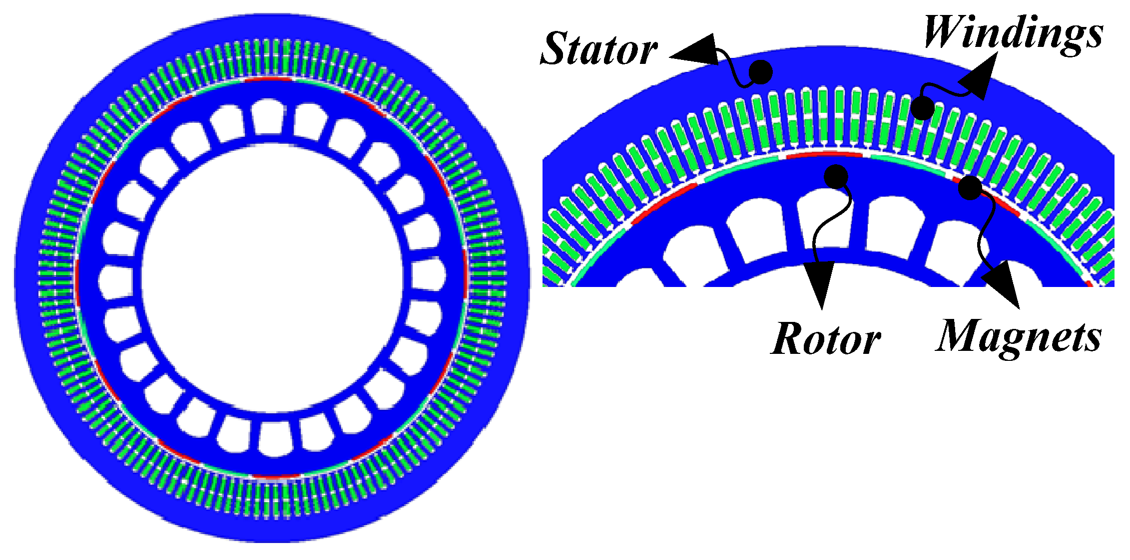
:1. Introduction
2. The Mathematical Model of the N*3-Phase PMSM
3. Topological Structure of the N*3-Phase PMSM Drive System
4. Robust Predictive Power Control of the Novel N*3-Phase PMSM
4.1. Drive System of the Novel N*3-Phase PMSM
4.2. Discrete Form Expression of the N*3-Phase PMSM
4.3. Sensitivity Analysis of Inductance Parameter Mismatch
4.4. Robust Predictive Power Control with One-Step Delay Compensation
5. Simulations
5.1. A. Control Performance Comparison between the Conventional PPC and Proposed R-PPC under the Charge State
5.2. B. Control Performance Comparison between the Conventional PPC and Proposed R-PPC under the Discharge State
6. Experimental Results
7. Conclusions
Author Contributions
Funding
Conflicts of Interest
References
- Demir, Y.; Aydin, M. A novel dual three-phase permanent magnet synchronous motor with asymmetric stator winding. IEEE Trans. Magn. 2016, 52, 1–5. [Google Scholar] [CrossRef]
- Rao, Z.; Zhang, Z.; Huang, S.; Long, Z.; Wu, G. Characteristics and current harmonic control of N* three-phase PMSG for HVDC transmission Based on MMC. Energies 2020, 13, 178. [Google Scholar] [CrossRef] [Green Version]
- Dwari, S.; Parsa, L. An optimal control technique for multiphase PM machines under open-circuit faults. IEEE Trans. Ind. Electron. 2008, 55, 1988–1995. [Google Scholar] [CrossRef]
- Zhang, W.; Wu, G.; Rao, Z.; Zheng, J.; Luo, D. Predictive Power Control of Novel N*3-phase PM Energy Storage Motor for Urban Rail Transit. Energies 2020, 15, 1578. [Google Scholar] [CrossRef] [Green Version]
- Han, X.; Jiang, D.; Zou, T.; Qu, R. Two-segment three-phase PMSM drive with carrier phase-shift PWM for torque ripple and vibration reduction. IEEE Trans. Power Electron. 2019, 34, 588–599. [Google Scholar] [CrossRef]
- Morel, F.; Shi, X.; Retif, J. A comparative study of predictive current control schemes for a permanent-magnet synchronous machine drive. IEEE Trans. Ind. Electron. 2009, 56, 2715–2728. [Google Scholar] [CrossRef] [Green Version]
- Li, S.; Liu, Z. Adaptive speed control for permanent magnet synchronous motor system with variations of load inertia. IEEE Trans. Ind. Electron. 2009, 56, 3050–3059. [Google Scholar]
- Tong, L. An SRF-PLL-based sensorless vector control using the predictive deadbeat algorithm for the direct-driven permanent magnet synchronous generator. IEEE Trans. Power Electron. 2014, 29, 2837–2849. [Google Scholar] [CrossRef]
- Wu, G.; Huang, S.; Wu, Q.; Rong, F.; Zhang, C.; Liao, W. Robust Predictive Torque Control of N∗3-Phase PMSM for High-Power Traction Application. IEEE Trans. Power Electron. 2020, 35, 10799–10809. [Google Scholar] [CrossRef]
- Wu, G.; Huang, S.; Wu, Q.; Zhang, C.; Rong, F.; Hu, Y. Predictive Torque and Stator Flux Control for N∗3-Phase PMSM Drives with Parameter Robustness Improvement. IEEE Trans. Power Electron. 2021, 36, 1970–1983. [Google Scholar] [CrossRef]
- Cortes, P.; Rodriguez, J.; Silva, C. Delay compensation in model predictive current control of a three-phase inverter. IEEE Trans. Ind. Electron. 2012, 59, 1323–1325. [Google Scholar] [CrossRef]
- Zhang, C.; Wu, G.; Rong, F.; Feng, J.; Jia, L.; He, J.; Huang, S. Robust fault-tolerant predictive current control for permanent magnet synchronous motors considering demagnetization fault. IEEE Trans. Ind. Electron. 2017, 65, 5324–5334. [Google Scholar] [CrossRef]
- Zhang, X.; Hou, B.; Mei, Y. Deadbeat predictive current control of permanent-magnet synchronous motors with stator current and disturbance observer. IEEE Trans. Power Electron. 2016, 32, 3818–3834. [Google Scholar] [CrossRef]
- Sozer, Y.; Torrey, D.A.; Mese, E. Adaptive predictive current control technique for permanent magnet synchronous motors. IET Power Electron. 2013, 6, 9–19. [Google Scholar] [CrossRef]
- Huang, S.; Wu, G.; Rong, F.; Zhang, C.; Huang, S.; Wu, Q. Novel predictive stator flux control techniques for PMSM drives. IEEE Trans. Power Electron. 2018, 34, 8916–8929. [Google Scholar] [CrossRef] [Green Version]
- Lyu, M.; Wu, G.; Luo, D.; Rong, F.; Huang, S. Robust nonlinear predictive current control techniques for PMSM. Energies 2019, 12, 443. [Google Scholar] [CrossRef] [Green Version]
- Moreno, J.C.; Huerta, J.M.; Gil, R.G.; Gonzalez, S.A. A robust predictive current control for three-phase grid-connected inverters. IEEE Trans. Ind. Electron. 2009, 56, 1993–2004. [Google Scholar] [CrossRef]
- Yang, M.; Lang, X.; Long, J.; Xu, D. Flux immunity robust predictive current control with incremental model and extended state observer for PMSM drive. IEEE Trans. Power Electron. 2017, 32, 9267–9279. [Google Scholar] [CrossRef]
- Yang, J.; Zheng, W.X.; Li, S.; Wu, B.; Cheng, M. Design of a prediction-accuracy-enhanced continuous-time MPC for disturbed systems via a disturbance observer. IEEE Trans. Ind. Electron. 2015, 62, 5807–5816. [Google Scholar] [CrossRef]
- Yang, J.; Li, S.; Yu, X. Sliding-mode control for systems with mismatched uncertainties via a disturbance observer. IEEE Trans. Ind. Electron. 2012, 60, 160–169. [Google Scholar] [CrossRef]
- Young, H.A.; Perez, M.A.; Rodriguez, J. Analysis of finite-control-set model predictive current control with model parameter mismatch in a three-phase inverter. IEEE Trans. Ind. Electron. 2016, 63, 3100–3107. [Google Scholar] [CrossRef]
- Xia, C.; Wang, M.; Song, Z.; Liu, T. Robust model predictive current control of three-phase voltage source PWM rectifier with online disturbance observation. IEEE Trans. Ind. Electron. 2012, 8, 459–471. [Google Scholar] [CrossRef]
- Rubagotti, M.; Raimondo, D.M.; Ferrara, A.; Magni, L. Robust model predictive control with integral sliding mode in continuous-time sampled-data nonlinear systems. IEEE Trans. Autom. Control 2010, 56, 556–570. [Google Scholar] [CrossRef] [Green Version]
- Liu, H.; Li, S. Speed control for PMSM servo system using predictive functional control and extended state observer. IEEE Trans. Ind. Electron. 2011, 59, 1171–1183. [Google Scholar] [CrossRef]
- Hu, F.; Luo, D.; Luo, C.; Long, Z.; Wu, G. Cascaded robust fault-tolerant predictive control for PMSM drives. Energies 2018, 11, 3087. [Google Scholar] [CrossRef] [Green Version]


| Parameters | Value |
|---|---|
| Rated power | 630 kW |
| Rated speed | 3000 r/min |
| Rated speed | 800 N·m |
| Rotational inertia (J) | 100 kg·m2 |
| Stator phase resistance (Ro) | 0.026 Ω |
| Number of pole pairs (np) | 4 |
| Inductances (Lo) | 5.572 mH |
| Flux linkage of PM (Ψro) | 0.992 Wb |
| Type of magnet | NdFeB |
| Magnet coercivity | 889 kA/m |
| Operating temperature | 20 °C |
Publisher’s Note: MDPI stays neutral with regard to jurisdictional claims in published maps and institutional affiliations. |
© 2021 by the authors. Licensee MDPI, Basel, Switzerland. This article is an open access article distributed under the terms and conditions of the Creative Commons Attribution (CC BY) license (https://creativecommons.org/licenses/by/4.0/).
Share and Cite
Zhang, W.; Li, Y.; Wu, G.; Rao, Z.; Gao, J.; Luo, D. Robust Predictive Power Control of N*3-Phase PMSM for Flywheel Energy Storage Systems Application. Energies 2021, 14, 3684. https://doi.org/10.3390/en14123684
Zhang W, Li Y, Wu G, Rao Z, Gao J, Luo D. Robust Predictive Power Control of N*3-Phase PMSM for Flywheel Energy Storage Systems Application. Energies. 2021; 14(12):3684. https://doi.org/10.3390/en14123684
Chicago/Turabian StyleZhang, Wenjuan, Yu Li, Gongping Wu, Zhimeng Rao, Jian Gao, and Derong Luo. 2021. "Robust Predictive Power Control of N*3-Phase PMSM for Flywheel Energy Storage Systems Application" Energies 14, no. 12: 3684. https://doi.org/10.3390/en14123684
APA StyleZhang, W., Li, Y., Wu, G., Rao, Z., Gao, J., & Luo, D. (2021). Robust Predictive Power Control of N*3-Phase PMSM for Flywheel Energy Storage Systems Application. Energies, 14(12), 3684. https://doi.org/10.3390/en14123684