Abstract
This article investigates the design, modeling, and fabrication of small-size (150 × 90 × 1.6 mm) broadband printed biconical antenna. The proposed antenna is intended for use a reference antenna for electromagnetic interference measurement inside the EMC chamber. The reflection coefficient (S11-parameter) is verified by modeling the equivalent circuit of the structure in terms of lumped elements. This structure offers a −10 dB impedance bandwidth (from 0.65 GHz to 2.3 GHz) with the tapered balun feeding method. Therefore, it has a high probability of estimating the electromagnetic waves emitted from several applications such as GSM, LTE, UMTS, 3G, Wi-fi, Bluetooth, ZigBee and more. The simulated standard antenna parameters are compatible with the measured parameters results. Furthermore, azimuth omnidirectional radiation pattern and well-realized gain (3.8 dBi) are achieved, reflecting good values of antenna factor compared to the commercial design.
1. Introduction
Recently, electronic devices have become more popular and are becoming smaller in size. According to their applications, the radiation of these devices is occupying the electromagnetic spectrum from DC frequency to GHz. Furthermore, electromagnetic interference (EMI) will occur between these devices as long as they share the same range [1]. The devices’ ability to work together without any effect against each other is called electromagnetic compatibility (EMC) [2]. Emission and immunity are essential criteria for EMI measurements. Three mandatory aspects should exist to generate EMI phenomena, the source of the electromagnetic waves, the victim affected by the source, and the path between the source and the victim. This path can be either radiated or conducted [3,4].
There are three radiation regions for each radiated element, near field region, reactive near-far field region (Fresnel), and far-field region (Fraunhofer) [5]. These regions have their radius (R) related to their wavelength and the higher dimension D, as shown in Figure 1. Two methods were proposed for EMI measurement based on radiated element regions and the power of the interference source. The far-field method uses an antenna to estimate the propagated electrical field inside the chamber [6]. In contrast, the near-field method utilizes probes to collect the induced magnetic and electrical field above the printed circuit board (PCB) [7].
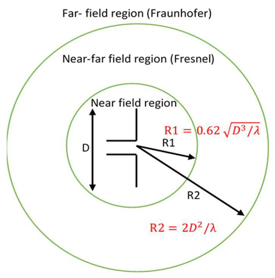
Figure 1.
Three field regions for any radiated element.
The antennas used for the EMC test should have specific characteristics such as wide bandwidth, high gain, omnidirectional radiation pattern, and good antenna factor. These designed antennas are intended to work in the very high frequency (VHF) and ultra-high frequency (UHF) bands (30–1000 MHz and 1000–3000 MHz, respectively) [8], to detect the interference emitted from the most critical applications in these bands such as GSM (850–900 MHz), LTE (1800 MHz), UMTS or 3G (2100 MHz), Wi-fi, Bluetooth, Zigbee and more (2400 MHz) [9,10]. VHF and UHF bands are classified based on the European Telecommunications Standards Institute (ETSI). The VHF band is covered by a biconical or log periodic antenna, while the horn antenna covers the UHF band above 1 GHz [11].
Several structures of the antennas were proposed to utilize in EMC measurement. In [12], the authors propose using characteristics of the sleeve dipole antenna for EMC measurement, which offers 86% size reduction compared to the conventional biconical antenna. The log-periodic dipole antenna’s frequency performances were improved in [13] using a saw-tooth shape feedline. The successive dipoles will be arranged in the horizontal plane and eliminate the unwanted vertical electric field component. A complementary log-periodic dipole array with cross-polarization was proposed in [14]. This structure has an array of dipole antennas orthogonal to dipoles of conventional log-periodic dipole antennas, offering a circular polarization without any hybrid junction. The width of the ridge of the double ridge guide horn (DRGH) antenna was tapered linearly in [15]. This process maximized the effective radiation aperture and reduced the beamwidth compared to conventional 1–18 GHz DRGH.
Classical antennas are large in size and heavy in weight. Therefore, using printed circuit technology (PCB) for antenna design is the best choice for this purpose. The microstrip antenna has many advantages such as its low cost, low profile, and ease to fabricate [16]. On the other hand, it suffers from the narrow bandwidth and low efficiency. The limited bandwidth is considered a big issue in EMC applications, which makes using the monopole and dipole printed antennas the best way to overcome this issue.
There will be a trade-off between the impedance bandwidth and the size, especially for this band from 0.5 to 3 GHz since low frequency needs a large size. Different kinds of printed antennas were proposed to serve EMC applications. In [17], a wideband (0.8–2.5 GHz) log-periodic printed antenna with 12 dipoles was presented. The authors of [18] show the design and development of a broadband bi-conical printed dipole antenna, where a wide impedance bandwidth was obtained with the help of balun feed and matching network. Ultra-wideband biconical (700 MHz–20 GHz) bilateral tapered slot antenna with dual-polarization was investigated for EMC measurements. Two studies [19,20] presented a new UWB Skeletal antenna for EMC measurements; the VSWR was better than the classical antenna that was used for the same purpose. In [21], the bulb shape was proposed with ultra-wideband (0.79–1 GHz and 1.37–15 GHz), where the wide impedance matching was achieved with the help of using the stepped part and feeding line. In [22], the design and model of a small elliptical planner dipole antenna for ultra-wideband EMC applications are presented.
EMC measurement needs an accurate and low uncertainty antenna to achieve a reliable antenna factor (AF) [23], where the AF represents the ratio of the electrical field strength on the surface of the antenna to the induced voltage across the antenna terminals [24].
This paper presents the design, modeling, and fabrication of an electrically small-size printed biconical antenna that serves as a reference antenna in the EMC measurements. The projection of the classical antenna inspires the printed biconical shape to offer wide bandwidth from 0.65 to 2.3 GHz. Furthermore, suitable values of AF along the covering frequency reflect the accuracy and low certainty of this design. This paper is organized as follows: Section 2 presents the antenna design with the parametric study. The standard antenna parameters and the antenna factor result are illustrated in Section 3. Section 4 highlights a comparison between the proposed antenna and commercial design, and finally, Section 5 presents a brief discussion.
2. Design Procedures
The choice of a biconical antenna has a significant advantage related to the shape of the radiation pattern. To be more specific, the radiation emission from the device under the test (DUT) has an unpredicted form and tends to be omnidirectional rather than present directive radiation. Therefore, using a directive antenna may lead to a missing EMI calculation due to the fact that the directive radiation pattern cannot cover the whole radiation emitted from DUT, i.e., omnidirectional antennas such as biconical antennas are preferred in these applications rather than directional antennas such as horn antennas [25].
2.1. Antenna Design
This antenna consists of two horizontal trapezoidal shapes based on FR-4 substrate with relative permittivity of and loss tangent , as illustrated in [16]. Some modifications were made in both shape and feeding methods to suit the EMC application. The idea of this design came from the dipole characteristics and the fact that the thicker width of the dipole leads to the wide bandwidth, and this thicker was changed to planner biconical, in order to achieve wide bandwidth [11]. These two trapezoidal shapes were placed in the top and bottom layer of the structure, and hence they created a virtual triangular slot with a width between them with (0.25 λ monopole) for each shape [26]. Therefore, when L = 0.25 λ = Wp = 71 mm, the length L dimension is adjusted to obtain the optimal result. The geometrical shape of the biconical printed antenna with a balun feed method is shown in Figure 2, while Table 1 list the optimum dimensions of antenna parameters
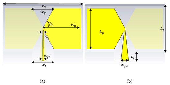
Figure 2.
The geometrical shape of the proposed antenna, (a) front view, (b) back view.

Table 1.
The optimal values of the overall parameters of the antenna.
2.2. Feeding Method
Balun is a transformer between the unbalanced port (antenna) and the balanced port (coaxial cable). It controls the current and decreases feeder radiation by providing a balanced current at each antenna’s legs. It prevents the current from propagation on the transmission line outer surface, to avoid distortion of the radiation properties [27]. The balun feed line provides wideband impedance matching. Therefore, it is more than suitable for this type of application, which requires broadband bandwidth. Two cases are studied here (the top and bottom transmission lines have the same and different widths). The balun feed method is dedicated to feeding this structure [28]. Tapered transmission lines are printed in the substrate layer’s front and back face with the same length and different width. The front transmission line (at the port side) has a width of connected to the 50 Ω of coaxial cable, while the tapered end of this line has a width of connected to the front face of the antenna. On the other hand, the back transmission line width (at the port side) is connected to the 50 Ω of coaxial cable, which works as the ground plane, while the tapered end of this line also has a width of connected to the back face of the antenna.
2.3. Parametric Study
This antenna was modeled and simulated with CST Microwave studio [29]. The parametric sweep is one of the critical facilities in this software that allowed us to sweep any parameter value to achieve the desired result. CST Microwave studio uses the finite integration technique (FIT) for its transient solver by discretizing the integral form of Maxwell’s equations. Figure 3 shows the grid shape of this method; three parameters were swept as follows.
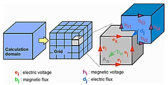
Figure 3.
The mesh system of finite integration technique.
2.3.1. The Width of the Virtual Slot between Two Trapezoidal Shapes
This parameter presents the transition from the trapezoidal shape () to the rectangular shape (. Since the value is still constant, the parameter is swept from 0 to 90 mm, and the corresponding S-parameter, as shown in Figure 4.
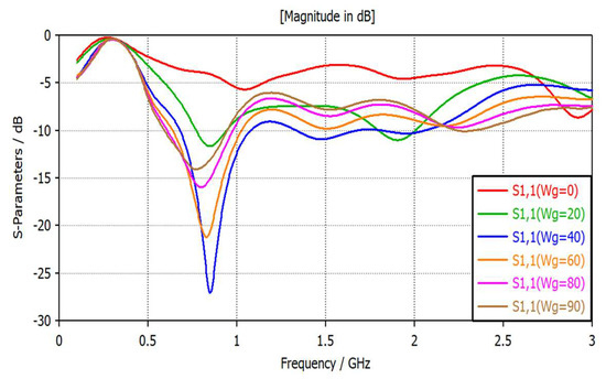
Figure 4.
Return losses vs. frequency for different values of .
It can be seen that there is no matching at (rectangular shape), while the return losses offer −12 dB at . The resonance frequency remained at the same point for different values of , and the effect is only carried on the bandwidth. The best value of the slot width that offers a good reflection coefficient and higher impedance bandwidth is mm. The discontinuity of each trapezoidal shape increases the reactive part of the input impedance of the antenna and hence, increases the standing wave ratio. The reactive part of the input impedance can be minimized with an increase in the cone angle mm) reflecting wide bandwidth [30].
2.3.2. Balun Feeding Method with the Straight Line and Tapered Line
As mentioned above, the balun lines are printed at the top and bottom side of the substrate to be one part of the planner biconical antenna. Figure 5 shows the difference between the use of straight lines and tapered lines. It is clear that the tapered lines provide an impedance bandwidth wider than straight lines.
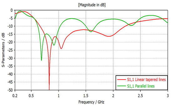
Figure 5.
Return losses vs. frequency for both straight and tapered feeding lines.
2.3.3. The Separation between the Trapezoidal Shapes (d)
The gap distance between the two opposite trapezoidal shapes significantly affects both impedance bandwidth and the gain, as shown in Figure 6a,b, respectively. The best value of separation distance is at d = 0 mm, as shown in the green curve, reflecting the maximum realized gain of 4 dBi gain and suitable impedance matching with broad bandwidth (0.7–2.3 GHz) [31].
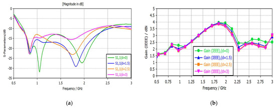
Figure 6.
(a) Return losses vs. frequency for different values of d in mm; (b) Realize gain vs. frequency for different values of d in mm.
2.4. Equivalent Circuit
The change in the width of the dipole affected the bandwidth directly. An equivalent circuit is involved in performing a comprehensive study of this antenna. The biconical antenna is derived from the classical planner dipole, and the most common lumped elements model consists of series impedance (C0 and L0) and parallel resonator (C1, L1 and R1) [32]. The series component presents the transmission line point while the parallel resonator is equivalent to the two resonance arms of the dipole, as shown in Figure 7.
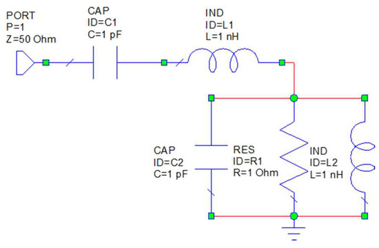
Figure 7.
Equivalent circuit of the typical dipole with default values of lumped elements.
Figure 7 presents the equivalent circuit for a narrowband dipole. Moreover, extra parallel resonators must be loaded to enable a wide frequency band to cover the whole frequency band from 0.7 to 2.3 GHz. Figure 8 presents the equivalent circuit modeling of a wideband biconical antenna in AWR Design Environment Software. The achieved S11-parameter from CST Microwave studio is imported to AWR Software, and the whole lumped elements are tuned to achieve the same response as imported S11-parameters. The return losses for both the proposed antenna and its equivalent circuits are shown in Figure 9, while Table 2 illustrates the optimum values of the equivalent circuit lamped elements.
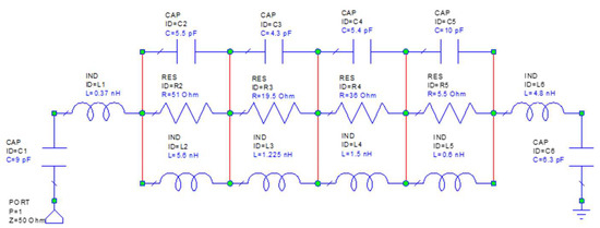
Figure 8.
Equivalent circuit of the wideband biconical printed antenna.
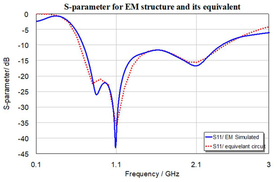
Figure 9.
S11-parameter for wideband biconical antenna and its equivalent circuit.
Table 2.
The optimum values of the lumped elements.
3. Fabrication Process and Measurement Results
The standard antenna parameters that measure whether this design is suitable for the EMC applications are estimated directly using the CST Microwave studio, except the antenna factor parameter, which is calculated from the achieved gain from the CST Microwave studio. This antenna was fabricated using the printed circuit technology, and the prototype of the fabricated design is shown in Figure 10. The RIGOL DSA875 Spectrum Analyzer, with directional coupler RIGOL VB 1032, is used to estimate the S-parameter, as shown in Figure 11. While the radiation characteristics are obtained using an anechoic chamber, the simulated and the measured results have a good agreement.
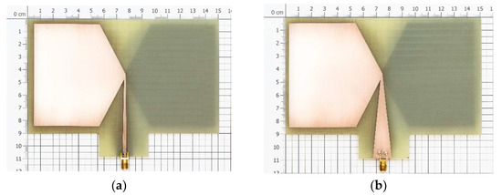
Figure 10.
Fabrication shape of the biconical antenna: (a) front view, (b) back view.
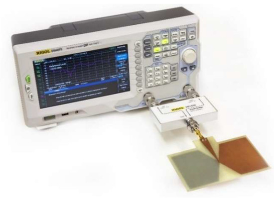
Figure 11.
Measurement of S11-parameter using the Spectrum analyzer.
3.1. Return Losses and VSWR
The reflection coefficients and the voltage standing wave ratio (VSWR) are the same coin’s two sides. Figure 12a shows the simulated and measured reflection coefficients of the design. It expresses about –30 dB return losses at a resonance frequency of 1 GHz, and the –10 dB impedance bandwidth starts from 750 MHz to 2.5 GHz. The measured result (S11-parameter) offers good agreement with the simulated result, reflecting VSWR < 2 in this broadband, as shown in Figure 12b, and it covers most of the EMC applications such as GSM (850–900 MHz), LTE (1800 MHz), UMTS or 3G (2100 MHz), Wi-fi and more (2400 MHz), which has a high probability of interference occurred.
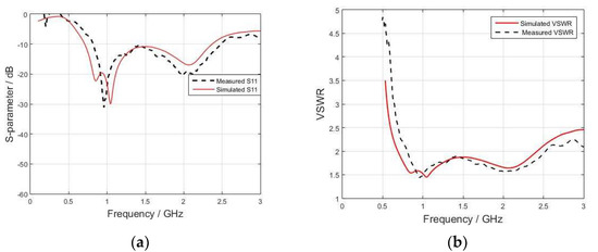
Figure 12.
(a) Simulated and measured return losses vs. frequency, and (b) simulated and measured VSWR vs. frequency.
3.2. Surface Current Distribution
The surface current distribution is the best way to explain the antenna’s behavior, since it describes the currents’ directions. Figure 13 shows the front and back view of the surface current distribution at 1 GHz. The tapered balun’s role of balancing currents in the red arrows in both front and rear sights is highlighted.
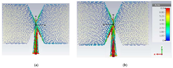
Figure 13.
Surface currents distribution at 1 GHz: (a) front view, (b) back view.
3.3. Gain and Radiation Efficiency
The gain measures how much the antenna gained the electromagnetic waves in one direction, rather than the total received waves. The gain standards are related to the radiation pattern; high gain is achieved in the directive radiation. Furthermore, the omnidirectional radiation offers low gain relativity, and it is certainly suitable for EMC applications. Figure 14a presents the simulated and measured gain versus frequency. The measure gain values are estimated using the comparison method with the help of an anechoic chamber. An acceptable level of gain was achieved with a maximum value of 3.8 dBi at 1.69 GHz. The radiation efficiency describes the ratio of the gain to the directivity of the antenna. More than 85% of simulated radiation efficiency is obtained for the overall operation band, as shown in Figure 14b.
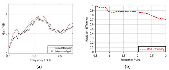
Figure 14.
(a) Gain in dBi vs. frequency, (b) radiation efficiency vs. frequency.
3.4. Antenna Factor (AF)
The antenna factor plays a critical role in measuring how useful the antenna is for use as a reference antenna for EMC measurements. Antenna factor can be defined as the ratio between the incident electrical field and the received voltage [33,34]. Equation (1) is used for calculating the antenna factor from the simulated and measured gain, respectively [35].
where is the wavelength, and is the gain of the antenna in dBi.
Figure 15 highlights the calculated antenna factor for printed biconical antenna from both simulated and measured gain. It can be seen that above 650 MHz, they are well-matched, and hence, the antenna factor increases in regular steps with an increase in the frequency reaching 2.5 GHz. The antenna factor increases in non-regular steps as the frequency increases above 2.5 GHz, despite reduced matching due to the antenna being directional rather than omnidirectional at 2.5 GHz.
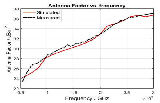
Figure 15.
Antenna factor in dBm−1 vs. frequency for printed biconical antenna.
3.5. Radiation Pattern
Figure 16 shows the 3-D radiation pattern of the antenna. It can be seen that the azimuth line or longitude line can be obtained with ph = 90° (the red line), where this line is almost equal in value along its radius. Furthermore, the elevation line or latitude line will be achieved at ph = 0° [35]. Both planes (azimuth and elevation) for four frequency bands (0.85 GHz, 1 GHz, 1.5 GHz, and 1.9 GHz) are shown in Figure 17. At lower frequencies, the omnidirectional behavior appears clearly. On the other hand, with high frequencies, the radiation pattern tends to be directional rather than omnidirectional, supporting the gain distribution curve with increasing frequency in Figure 14a. The radiation pattern measurement setup is shown in Figure 18.
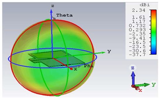
Figure 16.
3-D Simulated radiation pattern of the printed biconical antenna.
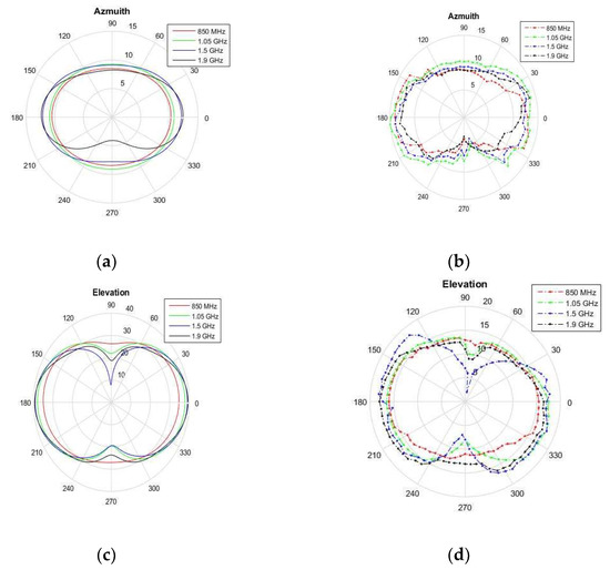
Figure 17.
Simulated and measured radiation pattern: (a) simulated azimuth, (b) measured azimuth, (c) simulated elevation, (d) measured elevation.
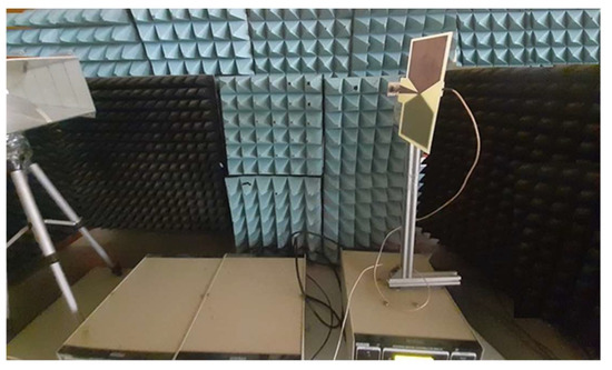
Figure 18.
Radiation pattern measurements setup inside the anechoic chamber.
4. Comparison between the Proposed Design and the Commercial Design
A brief comparison between the proposed and commercial designs (BicoLOG 20300) offered for sale on the AARONIA AG website by company of AARONIA in Germany is illustrated in Table 3 [36]. The specifications of the (BicoLOG 20300) are taken from the datasheet posted on the website. It can be seen that both designs are based on the biconical shape, which provides an omnidirectional radiation pattern. The proposed design is small and lightweight compared to the classical one, because it is based on the printed circuit technique. This technique has the disadvantage of small bandwidth (650 MHz–2.3 GHz) compared to the classical antenna (20 MHz–3 GHz). In contrast, the planar bi-conical antenna offers an acceptable realized gain of a maximum value of 3.8 dBi, while the classical antenna’s maximum gain is 1 dBi. Finally, both designs have good values of antenna factor, which makes them suitable for use as a reference antenna inside the EMC chamber.
Table 3.
Numerical comparison of antenna factor of the proposed antenna with the commercial antenna (BicoLOG 20300).
The achieved antenna factor values for the proposed design are in line with commercial antenna design values BicoLOG 20300, as illustrated in Table 4.
Table 4.
Antenna factor comparison of the proposed antenna with the commercial antenna (BicoLOG 20300).
5. Conclusions
An electrical small-size printed biconical antenna is designed, modeled, and fabricated to serve as a reference antenna in EMC measurements. The proposed antenna uses a tapered balun transformer to provide a balanced current and offers an impedance bandwidth from 650 MHz to 2.2 GHz with an acceptable VSWR. The realized gain of the antenna has a good value related to the omnidirectional antennas. This antenna’s behavior reflects an omnidirectional radiation pattern at the lower frequencies and gradually being a directional antenna with an increase in the rate toward 2.5 GHz. This design was compared with the commercial antenna design (BicoLOG 20300) for EMC measurement and achieved a good performance. It is worth mentioning that this antenna can be reconfigured to cover lower/higher frequency bands at the expense of size. For instance, an antenna size of 297 × 200 mm will cover a frequency band starting at 330 MHz up to 2.3 GHz. On the other hand, increasing the higher frequency band for this design required changing the sharp lines of the virtual triangular into curvature lines toward the antenna.
Author Contributions
Conceptualization, A.A.A. and Z.K.; methodology, A.A.A.; investigation, A.A.A. and Z.K.; resources, A.A.A. and Z.K.; writing—review and editing, A.A.A. and Z.K. All authors have read and agreed to the published version of the manuscript.
Funding
This research was supported by the Ministry of Education, Youth and Sports of the Czech Republic under the project OP VVV Electrical Engineering Technologies with High-Level of Embedded Intelligence CZ.02.1.01/0.0/0.0/18_069/0009855 and by the project SGS-2021-005: Research, development and implementation of modern electronic and information.
Institutional Review Board Statement
Not applicable.
Informed Consent Statement
Not applicable.
Data Availability Statement
Not applicable.
Conflicts of Interest
The authors declare no conflict of interest.
References
- Wang, X.; Chen, X.; Shi, X.; Bai, Y.; Wei, F.; Li, P. EMC design for an anti-jamming smart antenna system. In Proceedings of the 2009 5th Asia-Pacific Conference on Environmental Electromagnetics, Xi’an, China, 16–20 September 2009; pp. 196–199. [Google Scholar]
- Paul, C.R. Introduction to Electromagnetic Compatibility; John Wiley & Sons: Hoboken, NJ, USA, 2006; Volume 184. [Google Scholar]
- Kubík, Z.; Nikolayev, D.; Karban, P.; Skála, J.; Hromádka, M. Optimization of electrical properties of parallel plate antenna for EMC testing. J. Comput. Appl. Math. 2014, 270, 283–293. [Google Scholar]
- Kubík, Z.; Skála, J. Shielding Effectiveness Simulation of Small Perforated Shielding Enclosures Using FEM. Energies 2016, 9, 129. [Google Scholar] [CrossRef]
- Alnahwi, F.M.; Abdulhameed, A.A.; Swadi, H.L.; Abdullah, A.S. A Planar Integrated UWB/Reconfigurable Antenna with Continuous and Wide Frequency Tuning Range for Interweave Cognitive Radio Applications. Iran. J. Sci. Technol. Trans. Electr. Eng. 2019, 44, 729–739. [Google Scholar] [CrossRef]
- Stanislav, K.; Václav, M.; Jan, V.; Milan, A. Electromagnetic compatibility of arduino development platform in near and far-field. Int. J. Appl. Eng. Res. 2017, 12, 5047–5052. [Google Scholar]
- Namahoot, A.; Akkaraekthalin, P.; Chalermwisutkul, S. Design of a low-cost 1-20 GHz magnetic near-field probe with FR-4 printed circuit board. Int. J. RF Microw. Comput. Aided Eng. 2019, 29, e21958. [Google Scholar] [CrossRef]
- Mistry, K.K.; Lazaridis, P.I.; Zaharis, Z.D.; Chochliouros, I.P.; Loh, T.H.; Gravas, I.P.; Cheadle, D. Optimization of Log-Periodic TV Reception Antenna with UHF Mobile Communications Band Rejection. Electronics 2020, 9, 1830. [Google Scholar] [CrossRef]
- Alnahwi, F.; Abdulhameed, A.; Swadi, H.L.; Abdullah, A.S. A compact wide-slot UWB antenna with reconfigurable and sharp dual-band notches for underlay cognitive radio applications. Turk. J. Electr. Eng. Comput. Sci. 2019, 27, 94–105. [Google Scholar] [CrossRef]
- Alnahwi, F.; Al-Yasir, Y.I.A.; Abdulhameed, A.A.; Abdullah, A.S.; Abd-Alhameed, R. A Low-Cost Microwave Filter with Improved Passband and Stopband Characteristics Using Stub Loaded Multiple Mode Resonator for 5G Mid-Band Applications. Electronics 2021, 10, 450. [Google Scholar] [CrossRef]
- Kawakami, H.; Sato, G.; Wakabayashi, R.; Shimada, K. Conical log-periodic spiral antenna for microwave EMC/EMI measurement. In Proceedings of the IEEE Antennas and Propagation Society International Symposium 1997, Digest, Montreal, QC, Canada, 13–18 July 1997; pp. 538–541. [Google Scholar]
- Kim, K.-C.; Choi, B.J.; Jung, S.W. Characteristics of the Sleeve Dipole Antenna Used for EMC Applications. IEEE Access 2020, 8, 86957–86961. [Google Scholar] [CrossRef]
- Bang, J.; Han, C.; Jung, K.; Choi, J. High-Frequency Performance Improvement of LPDA for EMC/EMI Measurements. In Proceedings of the 2020 International Symposium on Antennas and Propagation (ISAP), Osaka, Japan, 25–28 January 2021; pp. 621–622. [Google Scholar]
- Kawakami, H.; Tanioka, M.; Wakabayashi, R. Circularly Polarized Log Periodic Dipole Antennas. In Proceedings of the 2020 International Applied Computational Electromagnetics Society Symposium (ACES), Monterey, CA, USA, 27–31 July 2020; pp. 1–2. [Google Scholar]
- Gerber, M.; Odendaal, J.W.; Joubert, J. DRGH Antenna With Improved Gain and Beamwidth Performance. IEEE Trans. Antennas Propag. 2019, 68, 4060–4065. [Google Scholar] [CrossRef]
- Balanis, C.A. Antenna Theory: Analysis and Design; John Wiley & Sons: Hoboken, NJ, USA, 2015. [Google Scholar]
- Mistry, K.K.; Lazaridis, P.I.; Zaharis, Z.D.; Xenos, T.D.; Tziris, E.N.; Glover, I.A. An optimal design of printed log-periodic antenna for L-band EMC applications. In Proceedings of the 2018 IEEE International Symposium on Electromagnetic Compatibility and 2018 IEEE Asia-Pacific Symposium on Electromagnetic Compatibility (EMC/APEMC), Suntec City, Singapore, 14–18 May 2018; pp. 1150–1155. [Google Scholar]
- Ahirwar, S.; Ramakrishna, D.; Pandharipande, V. Design and development of a broadband planar dipole antenna. In Advances in Decision Sciences, Image Processing, Security and Computer Vision; Springer: Cham, Switzerlands, 2020; pp. 185–193. [Google Scholar] [CrossRef]
- Lin, F.; Qi, Y.; Fan, J.; Jiao, Y.-C. 0.7–20-GHz dual-polarized bilateral tapered slot antenna for EMC measurements. IEEE Trans. Electromagn. Compat. 2014, 56, 1271–1275. [Google Scholar] [CrossRef]
- Mallahzadeh, A.; Pazoki, R.; Karimkashi, S. A new UWB skeletal antenna for EMC applications. In Proceedings of the 2007 International Symposium on Microwave, Antenna, Propagation and EMC Technologies for Wireless Communications, Hangzhou, China, 16–17 August 2007; pp. 543–546. [Google Scholar]
- Hacene, Y.; Shuguo, X. Study of a novel ultra-wideband monopole antenna for EMC measurement applications. In Proceedings of the 2012 6th Asia-Pacific Conference on Environmental Electromagnetics (CEEM), Shanghai, China, 6–9 November 2012; pp. 393–395. [Google Scholar]
- Tziris, E.N.; Cosmas, J.P.; Zaharis, Z.D.; Xenos, T.D.; Lazaridis, P.I.; Mistry, K.M.; Glover, I.A. Invasive weed optimized planar elliptical dipole antenna for ultra-wideband EMC applications. In Proceedings of the 2018 IEEE International Symposium on Electromagnetic Compatibility and 2018 IEEE Asia-Pacific Symposium on Electromagnetic Compatibility (EMC/APEMC), Suntec City, Singapore, 14–18 May 2018; pp. 233–236. [Google Scholar]
- Sapuan, S.Z.; Kazemipour, A.; Jenu, M.Z.M. Direct feed biconical antenna as a reference antenna. In Proceedings of the 2011 IEEE International RF & Microwave Conference, Seremban, Malaysia, 12–14 December 2011; pp. 5–8. [Google Scholar]
- Alijani, M.G.; Sheikh, S.; Kishk, A. Development of Closed-Form Formula for Quick Estimation of Antenna Factor. In Proceedings of the 2021 15th European Conference on Antennas and Propagation (EuCAP), Dusseldorf, Germany, 22–26 March 2021; pp. 1–5. [Google Scholar]
- Sapuan, S.Z.; Jenu, M.Z.M. Time domain analysis of direct-feed biconical antenna for Antenna calibration and EMC measurement. In Proceedings of the 2016 IEEE Asia-Pacific Conference on Applied Electromagnetics (APACE), Langkawi, Malaysia, 11–13 December 2016; pp. 198–201. [Google Scholar]
- Kuo, L.-C.; Chuang, H.-R.; Kan, Y.-C.; Huang, T.-C.; Ko, C.-H. A study of planar printed dipole antennas for wireless communication applications. J. Electromagn. Waves Appl. 2007, 21, 637–652. [Google Scholar] [CrossRef]
- Uduwawala, D. A Comprehensive Study of Resistor-Loaded Planar Dipole Antennas for Ground Penetrating Radar Applications. Ph.D. Thesis, KTH Royal Institute of Technology, Stockholm, Sweden, 2006. [Google Scholar]
- Proudfoot, P.M. A Printed Circuit Folded Dipole with Integrated Balun; Rome Air Development Center Griffiss AFB NY, 1989; Available online: https://www.tib.eu/de/suchen/id/ntis%3Asid~oai%253Ads2%253Antis%252F531a0f0502b803781c022a7b (accessed on 24 June 2021).
- Studio, C.M.J.C.S.T. 3D EM Simulation Software; 2014; Available online: https://www.microwavejournal.com/authors/2569-computer-simulation-technology-cst-darmstadt-germany?page=2 (accessed on 24 June 2021).
- Islam, M.R. Study and Implementation of Wideband Bow-Tie Antennas. 2017. Available online: https://digitalcommons.georgiasouthern.edu/etd/1674 (accessed on 24 June 2021).
- Sapuan, S.Z.; Herie, F.H.; Jenu, M.Z.M. A new small sized wideband biconical antenna for Electromagnetic Compatibility (EMC) measurements. In Proceedings of the 2016 IEEE Asia-Pacific Conference on Applied Electromagnetics (APACE), Langkawi, Malaysia, 11–13 December 2016; pp. 222–225. [Google Scholar]
- Tuovinen, T.; Berg, M. Impedance dependency on planar broadband dipole dimensions: An examination with antenna equivalent circuits. Prog. Electromagn. Res. 2014, 144, 249–260. [Google Scholar] [CrossRef]
- Sapuan, S.Z.; Jenu, M.Z.M.; Kazemipour, A. Calibration of calculable wideband direct feed biconical antenna for EMC measurements. In Proceedings of the 2013 Asia-Pacific Symposium on Electromagnetic Compatibility (APEMC), Melbourne, VIC, Australia, 20–23 May 2013; pp. 1–4. [Google Scholar]
- McLean, J.; Sutton, R.; Hoffman, R. Interpreting Antenna Performance Parameters for EMC Applications: Part 3: Antenna Factor; 2004; Available online: https://www.tdkrfsolutions.tdk.com (accessed on 24 June 2021).
- McLean, J.; Sutton, R.; Hoffman, R.; TDK RF Solutions. Interpreting Antenna Performance Parameters for EMC Applications Part 1: Radiation Efficiency and Input Impedance Match; 2007; Available online: https://www.tdkrfsolutions.tdk.com (accessed on 24 June 2021).
- BicoLOG 20300. (n.d.). Aaronia Shop. Available online: https://aaronia-shop.com/products/biconical-antenna-bicolog-20300 (accessed on 24 June 2021).


Publisher’s Note: MDPI stays neutral with regard to jurisdictional claims in published maps and institutional affiliations. |
© 2021 by the authors. Licensee MDPI, Basel, Switzerland. This article is an open access article distributed under the terms and conditions of the Creative Commons Attribution (CC BY) license (https://creativecommons.org/licenses/by/4.0/).