Article

Hydrogen Dispersion and Ventilation Effects in Enclosures under Different Release Conditions

by
Dorota Brzezińska
Faculty of Process and Environmental Engineering, Lodz University of Technology, Wolczanska 213, 90-924 Lodz, Poland
Energies 2021, 14(13), 4029; https://doi.org/10.3390/en14134029
Submission received: 10 May 2021 / Revised: 25 June 2021 / Accepted: 29 June 2021 / Published: 4 July 2021
(This article belongs to the Special Issue Advances in Hydrogen Energy Production and Storage)

Abstract

:
Hydrogen is an explosive gas, which could create extremely hazardous conditions when released into an enclosure. Full-scale experiments of hydrogen release and dispersion in the confined space were conducted. The experiments were performed for hydrogen release outflow of 63 × 10−3 m3/s through a single nozzle and multi-point release way optionally. It was found that the hydrogen dispersion in an enclosure strongly depends on the gas release way. Significantly higher hydrogen stratification is observed in a single nozzle release than in the case of the multi-point release when the gas concentration becomes more uniform in the entire enclosure volume. The experimental results were confirmed on the basis of Froud number analysis. The CFD simulations realized with the FDS code by NIST allowed visualization of the experimental hydrogen dispersion phenomenon and confirmed that the varied distribution of hydrogen did not affect the effectiveness of the accidental mechanical ventilation system applied in the tested room.

1. Introduction

Traditional industrial use of hydrogen has been recently widened due to its impressive energy potential combined with minimal environmental impact. It is mostly motivated by regulations relative to climate change prevention and the reduction of fossil fuel demand, as hydrogen is considered a particularly clean and sustainable fuel, mainly when produced from renewable sources [1]. Hydrogen is a clean energy source as input for fuel cells, where, in an electrochemical reaction, energy is released as an electrical potential and heat–chemical energy [2]. The chemical energy is there directly converted to electrical energy, unlike traditional generators where chemical energy is initially converted to mechanical energy. In consequence, in the fuel cells, there is neither combustion nor emission. In vehicles, polymer electrolyte membrane (PEM) fuel cells are used most often because they are compact systems, and their start-up process is extremely fast [3].
There are many methods of hydrogen production, including bio-solutions such as dark fermentation of residual algae biomass, which give a wide perspective for the sustainable solving of energy issues in the modern technological world [4]. The physical properties of hydrogen that motivate its use make it desirable, mainly its high energy capacity per unit of mass, which is three times higher than that of gasoline, and no emissions of pollutants during combustion. These characteristics make hydrogen more attractive than other fuels [1,5,6]. As a consequence, a robust expansion of hydrogen fuels is observed in the transportation area, and hydrogen fuel cell vehicles (FCVs) are introduced dynamically [7]. The diagram in Figure 1 presents FCVs declared targets of deployment from 2017 to 2030 for selected exemplar representative countries: Japan, Netherlands, and France [7].
The presented examples demonstrate a global increasing tendency, which means that in 10 years, the FCVs market would be significant. The problem of preparing a safe infrastructure for these cars becomes an urgent goal. For example, in Europe, the Directive 2014/94/EU [8] strongly promotes alternative fuels in transport, putting electromobility development as the most critical task.
All of the above benefits of using hydrogen as a vehicle fuel and associated regulations make it easier to anticipate an intense increase in FCVs. However, despite the mentioned positives, users should be aware that the low density of hydrogen (especially in its high-pressure gas phase, considered here, which is ~7% the density of air) requires a large volume of gas, which is carried to provide a reasonable driving range [9]. The lowest molecular weight of hydrogen also means that the energy density of a hydrogen-air mixture, and hence the power output, is significantly reduced [2]. Moreover, hydrogen is an extremely hazardous gas [10,11]. The reason is mainly due to its explosive properties. It is reported that the increasing usage of alternative fuel vehicles (electricity, hydrogen, LNG, LPG, etc.) has significantly altered vehicle fire characteristics [12]. For example, the hydrogen flame velocity is eight times higher than that for methane. Moreover, its flammable limits range from 4% to 75%, the autoignition temperature is 585 °C when methane is ~540 °C, and its ignition energy is 1/10 of methane made [1]. Additionally, hydrogen is an odorless, colorless, and tasteless gas that makes the human senses unable to detect it [13].
The understanding of hydrogen behavior in confined spaces is often supported by computational fluid dynamics (CFD) simulations. Various CFD codes are used for predicting hydrogen release and distribution, and their accuracy of real mapping phenomena varies depending on different parameters. For example, in 2009, Venetsanos et al. indicated the most accurate turbulence models for HySafe software [14,15]. In 2014, Jäkel et al. analyzed Ansys CFX as a complete sequence tool for the release, distribution, and accumulation of released hydrogen [16]. In 2015, Melideo and Baraldi worked again on Ansys CFX software and its accuracy in modeling hydrogen behavior in tanks [17]. Moreover, hydrogen stratification phenomenon modeling with Ansys CFX was investigated in 2016 by Hoyes and Ivings [18]. In 2018, Brzezinska demonstrated FDS software’s possibility for hydrogen dispersion under ventilation conditions modeling [13]. In 2019, Giannissi and Venetsanos analyzed the humidity’s influence on hydrogen release conditions using the CFD code, ADREA-HF [19]. Moreover, in 2019, Tolias et al. have published Best Practice Guidelines (BPG) in numerical simulations for Fuel Cell and Hydrogen applications where LES and RANS turbulence models have suggested the independence of the phenomena modeled [20,21,22]. The newest research in the field of hydrogen dispersion modeling published in 2020 by Lach et al. also demonstrates the possibility of predicting a pressure peaking phenomenon by Pmix and Rmix models [23].
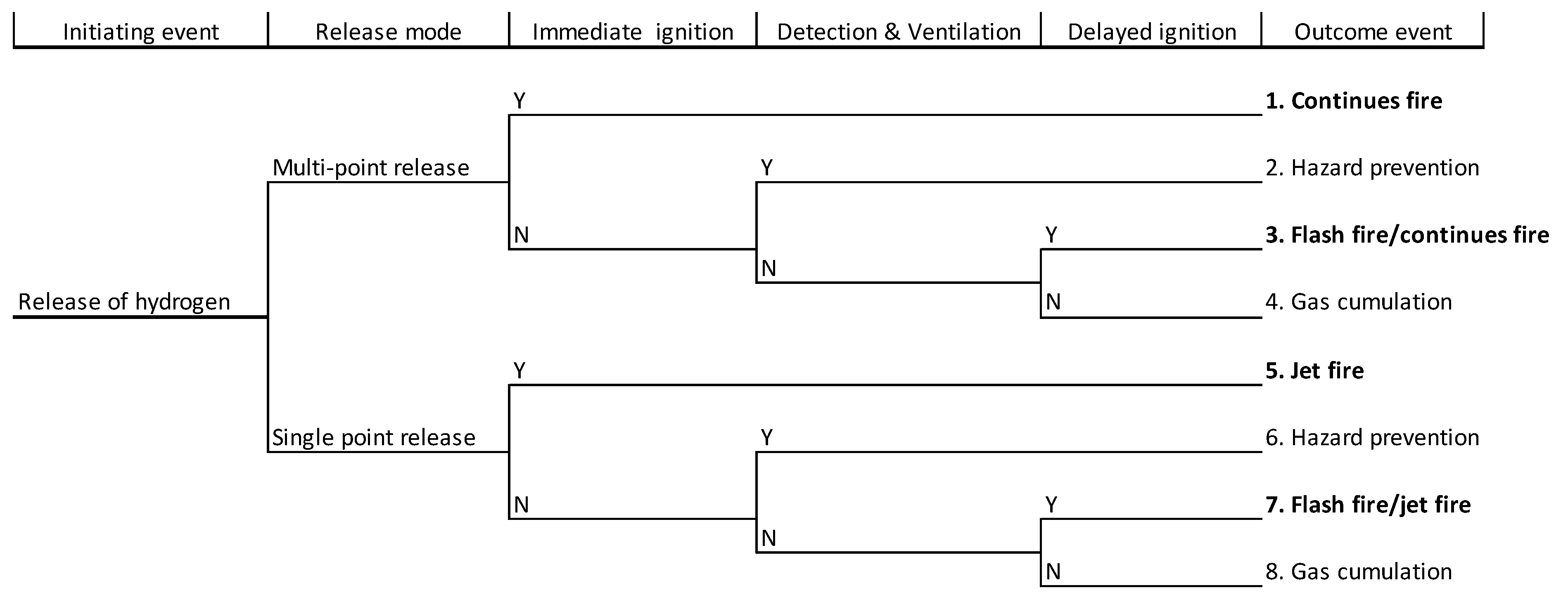
In the case of hydrogen release from the vehicle, several scenarios are presented in the event tree in Figure 2. As the initiating event, hydrogen release from a car’s installation is taken into account, with eleven different outcomes considered. Factors identified herein as impacting the end event were: type of discharge (permeation or failure release), multivalve reaction, potential ignition, gas detection in the enclosure, and ventilation system working.
Flashfire or an explosion could be considered a worst-case scenario and is expected in four situations. An important and influential parameter is the immediate ignition source caused by hot elements in the car. The delayed ignition due to hot elements in another vehicle entering the car park or other hot surfaces can be effective only when the hydrogen cloud can stay in a concentration above the lower flammable limit (LFL). Such a situation can occur when a ventilation system does not work, and this may happen when there is a lack of detection or ventilation system [24,25,26].
The continuous hydrogen failure release can be realized in two ways: through a singular nozzle, or through many points evenly distributed over a carcass’s surface. The first case could happen when leakage in the tank or installation causes direct hydrogen to spread into the car park. The second case happens when hydrogen leakage occurs inside a vehicle case, and the gas spreads outside as a multi-point release. The two cases can be a reason for the different hydrogen behavior in the car park space, which directly motivated the research presented in this paper.

2. Materials and Methods

The research material presented in this paper could be divided into three main phases. The first phase represents full-scale experiments of continuous hydrogen release from a single nozzle or a multi-point release source. The second phase was CFD modeling of the phenomena observed in the experiments and comparing the simulation results with the experimental data. Finally, based on the CFD model, a mechanical ventilation system was verified under both hydrogen release ways.

2.1. Hydrogen Dispersion Experiment

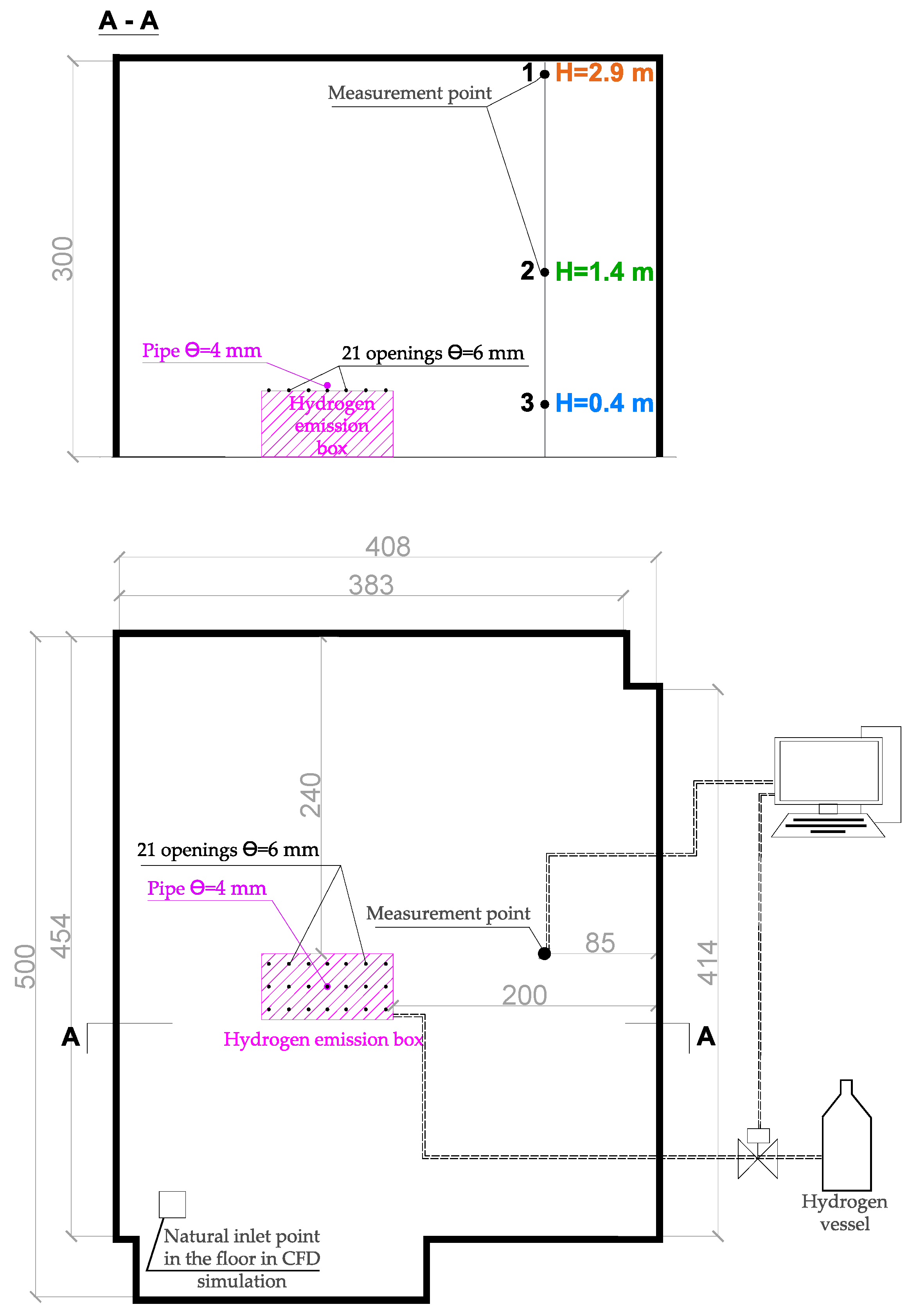
Measurements were carried out in a confined room of approximately 60 m3 volume presented in Figure 3. Hydrogen in the gas phase was released from a cylinder of 6 m3 volume and 140 bar pressure and supplied to the room through a box connected with the cylinder with the 10 m long pipe of ϴ = 4 mm. Hydrogen was released through a pressure reducer under a final pressure of 8 bar. The gas flow was measured with a certified Mass Stream Instrument D Series, calibrated to a flow rate of 1.63 × 10⁻³ m3/h with a density of 0.65 kg/m3. The upper surface of the dimensions 1.0 m × 0.5 m had 21 openings of ϴ = 6 mm. Hydrogen concentration was measured by catalytic sensor VQ-21, with a sensing range from 0% to 100% at the lower explosive limit (LEL) 0.004. The test stand allowed measurement of the hydrogen propagation in six measurement points located at different room heights. The experimental layout with all necessary dimensions is presented in Figure 3, and photos of the equipment are shown in Figure 4. Results of the experiments are presented in Section 3. In each experiment, the hydrogen concentration in the laboratory room reached between 28% LFL and 100% LFL (depending on the conducted test). In the experimental enclosure, the temperature was 283K.
The experiments were realized with a hydrogen volume outflow of 1.63 × 10⁻³ m3/s, and in two various release ways: through a single nozzle (Test 1) or through 21 release points simultaneously (multi-point release) (Test 2).

2.2. CFD Modeling of the Hydrogen Dispersion

For the CFD simulations, the Fire Dynamic Simulator (FDS) version 6.3.2 of the National Institute of Standards and Technologies (NIST), Gaithersburg, Maryland, USA was used. The FDS enables the performance of three-dimensional simulations of heat transfer and mass flow. It is based on the numerical solution of the Navier Stokes equations. Initially, the program was created for fire-driven fluid flow modeling. However, the authors’ experience shows that it can also be successfully used to analyze the spread of gases in enclosures [13,27,28,29,30]. The software uses a large eddy simulation (LES) turbulence model appropriate especially for buoyancy flows, which is widely used for hydrogen dispersion phenomenon modeling [21,31,32,33,34]. The FDS is also used for buoyancy modeling, natural and mechanical ventilation system analyses, nozzles outflows, etc. [35,36]. Similar to the experiments, hydrogen in the simulations was performed in the room of the box. In Test 1, the gas emission was realized through the single nozzle, and in Test 2—through the 21 openings in the box’s cover. The hydrogen release parameters correspond to the experiments and are presented in Table 1.
For the simulations, the same room size and its parameters as during the experiments were used. Moreover, the hydrogen concentration measurement points in the simulations were placed in similar positions to the experiments. The grid used for the simulation was 0.05 m in each direction. Additionally, a small opening in the floor of the model (0.05 m × 0.05 m) was used to represent the experimental room leaks and protect the simulation against undesirable pressure increases. As described under the experiments, the initial pressure was equal in the model to 1013 hPa, and the initial temperature was 10 °C.
For the 3D model creation and its discretization, the Pyrosim software version 2020.5 was used. The simulation results visualization was realized with the Smokeview (SMV) application, version 6.7.15. Figure 4 shows the FDS models used for the simulations relative to the experimental layout described earlier.

3. Results

3.1. Hydrogen Dispersion Analyses

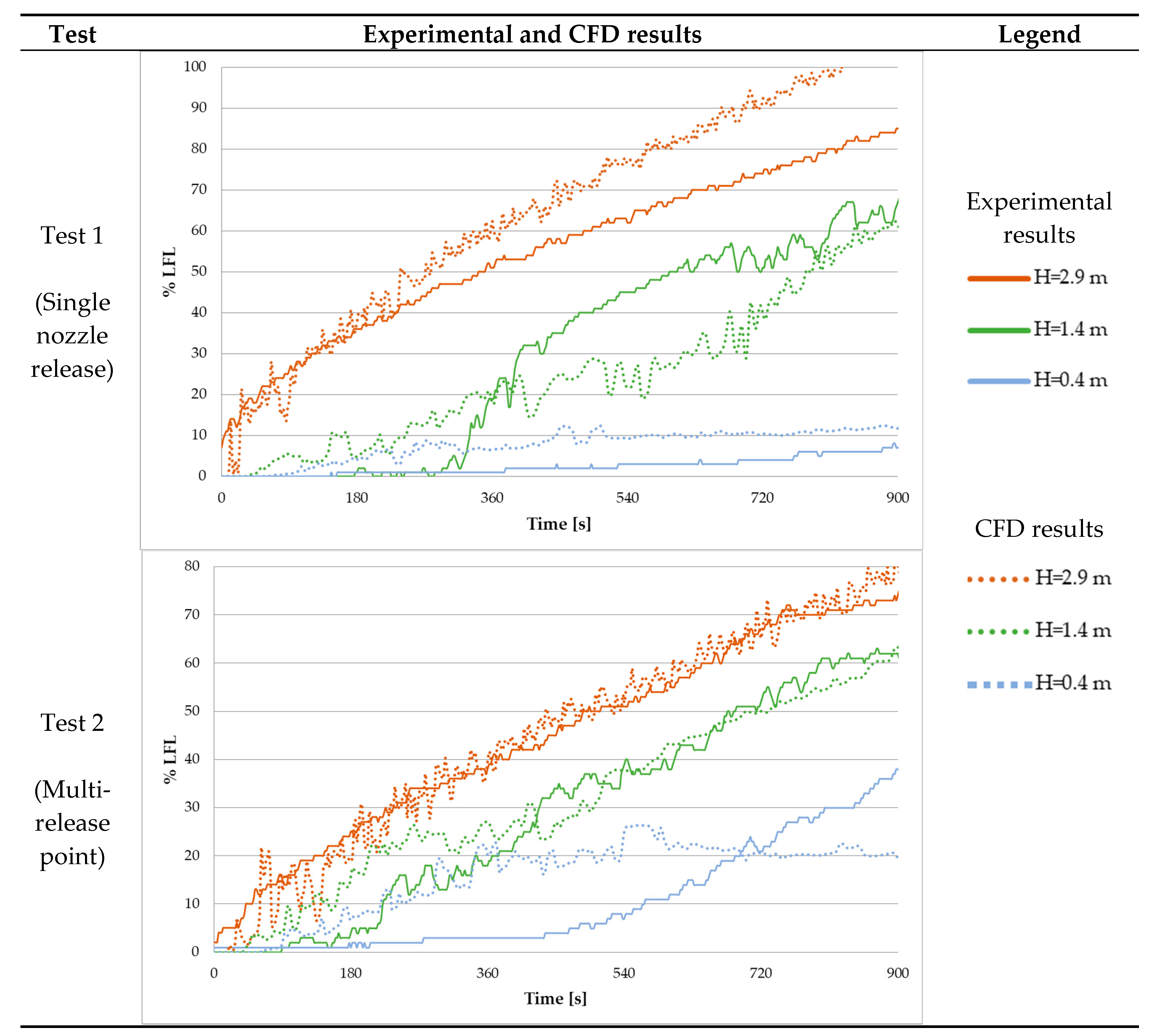
The experimental and simulated results were compared. The graphs in Figure 5 present the hydrogen concentration at the selected heights of 2.9 m, 1.4 m, and 0.4 m received from the experimental tests and the relative CFD simulations. The results of the hydrogen concentration in the enclosure are presented for the single nozzle and multi-point release ways.
In Figure 6, the graphical results of the second phase of the project, which were the CFD simulations, are presented for the single nozzle and multi-point release.
The experiments and CFD simulations confirm that continuous hydrogen release in a sealed enclosure finally leads to the LFL exceeding and can create explosive hazards. This phenomenon is expected sooner in the case of a single-release point than when hydrogen is emitted through multi-points. As it was presented in the event tree (Figure 2), a ventilation system could be an effective system for hydrogen explosive hazards mitigation. The final stage of the presented research is verifying the mechanical ventilation system if it is equally effective in both tested hydrogen emission methods.

3.2. The Hazard Mitigation by a Ventilation System

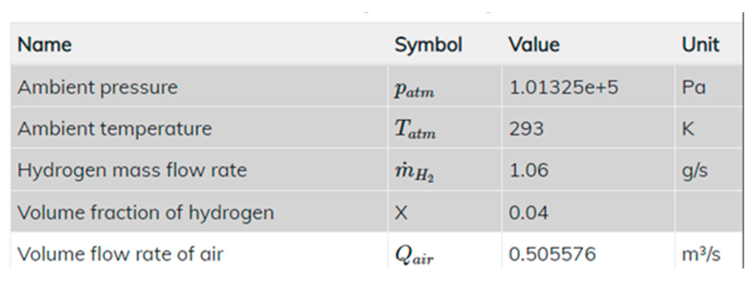
The ventilation system’s objective is to remove hydrogen released in the enclosure to keep its concentration below LEL = 4%. The required capacity of the mechanical ventilation system was calculated using the e-Laboratory FCH2Edu—a virtual laboratory of hydrogen and fuel cells (HFC) calculator from Ulster University [38]. The minimal exhaust outflow was appointed as equal to 0.5 m3/s (Figure 7). In both tests, the exhaust vent was placed in the ceiling, and the air supply vent was placed on the floor to ensure no hydrogen propagation through it.
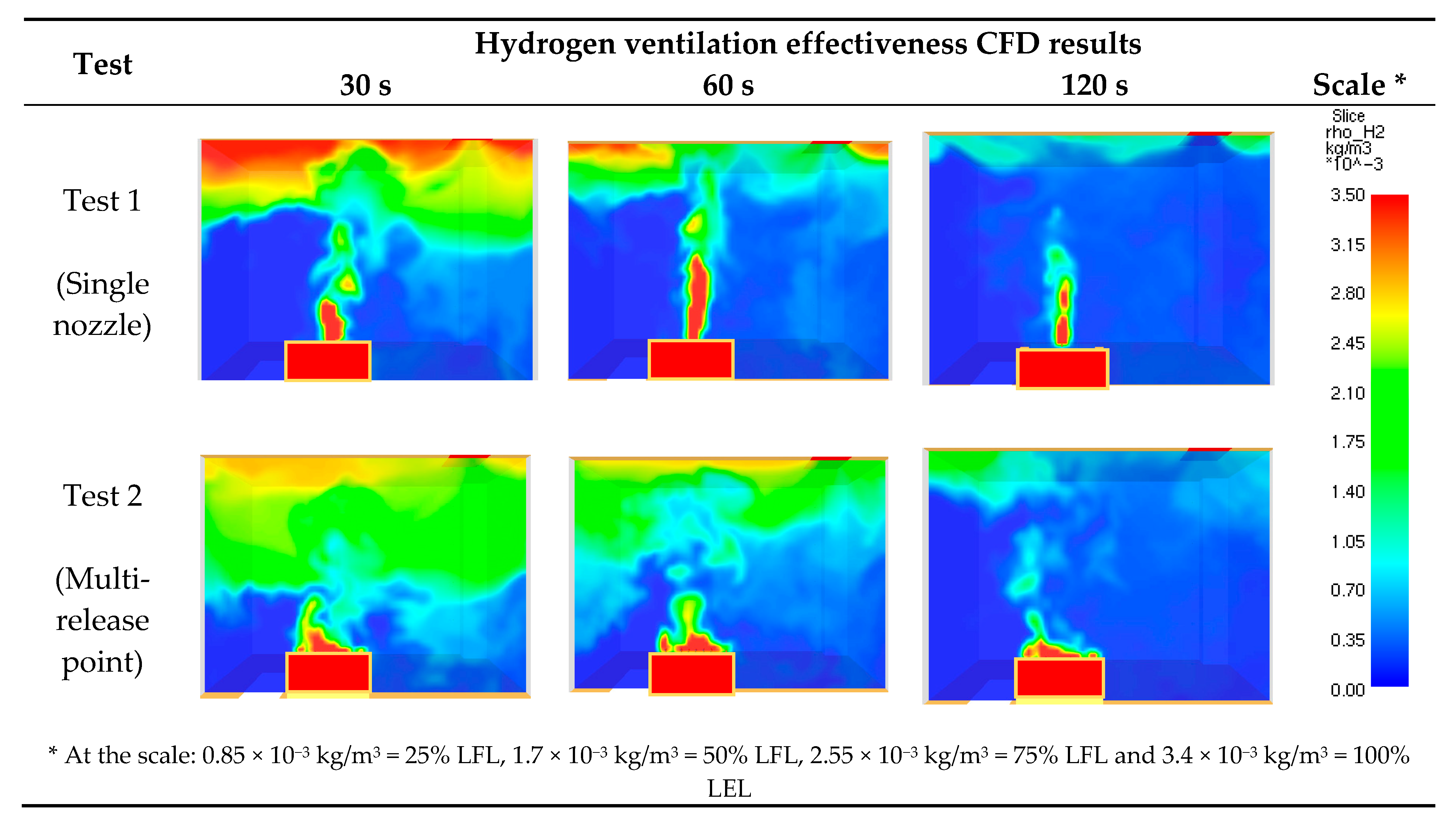
For better visualization of the ventilation system effectiveness, the simulations started 900 s after the hydrogen release begun, when the gas concentration was consistent with the CFD results shown in Figure 6, after the time of 900 s. The visualization of the hydrogen ventilation effectiveness CFD simulation is presented in Figure 8.

4. Discussion

The experimental results presented in Figure 5 demonstrate a significant influence of the hydrogen release method on the gas dispersion phenomenon. It was shown that for the same hydrogen volume outflow, a single nozzle release causes a higher velocity of gas release, and its rising upwards in contrast to the multi-point release. Consequently, a much higher level of hydrogen stratification was observed in the room under the single nozzle release, which causes higher gas concentration under the ceiling and a lower concentration near the floor in contrast to the multi-point release case.
A theoretical confirmation of the presented experimental results was realized on the basis of Froud number analysis, which can represent gas plume characterization, indicating the influence of gravity on the fluid motion. In effect, it could be used to evaluate how much the buoyancy force affects the hydrogen dispersion [39]. The Froud number was calculated based on Equation (1), and the Fr~1 could indicate the luck of the buoyancy effect and diffusive distribution of the gas [6]. The Froud number values achieved for the experimental parameters are shown in Table 2.
Fr = U2/gD
where:
U—velocity at the outflow [m/s],
g—gravitational acceleration [m/s2],
D—outflow diameter [m].
Table 2. Froud number values for the experimental parameters.
Test No.Hydrogen Release MethodU [m/s]D [m]Fr
Test 1Single nozzle release 129.784.00 × 10−34.29 × 10⁵
Test 2Multi-point release 2.752.75 × 10−22.80 × 101
The Froud numbers received for the single nozzle release appeared to be around five orders of magnitude larger than in the multi-point release. This confirmed significant differences in the hydrogen buoyancy between the tested release forms. Concluding, the experimental results confirmed that the lower the Froud number, the lower the buoyancy force influences the hydrogen dispersion.
The CFD simulations demonstrated the buoyancy diversity phenomenon, which allowed us to visualize the hydrogen concentration increase during the gas release. Figure 6 presents the gas distributions after 300 s, 600 s, and 900 s from the release beginning. Additionally, the simulation results of the hydrogen concentration in the measurement points were presented together with the experimental results (Figure 5). Although the CFD results tend slightly to overestimate the modeled hydrogen concentration, the overall stratification and buoyancy phenomenon in both tests were represented correctly. A better agreement between the results could be obtained when the default turbulence model and its coefficients in the FDS were modified, requiring additional simulations [40]. This research is planned in the next step and will be published separately. However, it must be aware that the presented overestimation of the CFD model makes it more conservative than the measurements, which could give a safety margin to the engineering analyses.
The same simulation model as for the hydrogen release and dispersion phenomenon was used to verify the ventilation system. The CFD results presented in Figure 8 demonstrate that the ventilation efficiency in both cases was remarkably similar. Regardless of the type of gas release, the ventilation system removed all hydrogen accumulated in the room within the first 120 s and started to discharge the gas. This observation is highly significant in practice, giving guidance for safety ventilation systems design.

5. Conclusions

The full-scale experiments of hydrogen release and dispersion in the confined space were performed. Hydrogen was released into the room in two ways: through a single nozzle, and through 21 points evenly distributed over the surface of the emission box (multi-point release). In both cases, the hydrogen release outflow was equal to 1.63 × 10⁻³ m3/s. It was found that hydrogen dispersion in an enclosure strongly depends on the method of gas release. Much higher hydrogen stratification in the room was observed under single nozzle release conditions. Under the multi-point release, when the buoyancy motions were lower, the gas concentration became much more uniform in the entire enclosure. A theoretical confirmation of the presented experimental results was obtained on the basis of Froud number analysis, which indicates the buoyancy motion of a fluid dispersion. The experiments were strongly confirmed with the CFD simulations. However, an overestimation in the CFD results, especially under the ceiling, was observed, which suggests that accidental hydrogen release simulations using the default turbulence model of the FDS code could give more conservative results than expected in experiments. The FDS users have to be aware of that, but at the same time, such simulations put designers on the safe side when safety systems are designed. The CFD results additionally confirmed a similar level of mechanical ventilation system effectiveness in both cases of hydrogen release, giving guidance for the safety ventilation system design.
The lessons learned from the presented research have been implemented in the actual methods of detection and accidental ventilation design methods used in Poland in spaces endangered by the release of hydrogen.

Funding

This research received no external funding.

Institutional Review Board Statement

Not applicable.

Informed Consent Statement

Not applicable.

Acknowledgments

I gratefully acknowledge the IV Fire Brigade Station in Lodz for kindly providing a room for the tests in which the measurements were taken, Gazex Sp z o.o., and Metalchem Sp z o.o. for providing the hydrogen detectors and flow meter, which was applied in the experiments.

Conflicts of Interest

The authors declare no conflict of interest.

References

  1. Kaplan, R.; Kopacz, M. Economic Conditions for Developing Hydrogen Production Based on Coal Gasification with Carbon Capture and Storage in Poland. Energies 2020, 13, 5074. [Google Scholar] [CrossRef]
  2. Lanz, A.; Heffel, J.; Messer, C. Hydrogen Fuel Cell Engines and Related Technologies—Module 3: Hydrogen Use in Internal Combustion Engines; College of the Desert: Palm Desert, CA, USA, 2001. [Google Scholar]
  3. Arunkumar, J. An Assessment on Polymer Electrolyte Membrane Fuel Cell Stack Components, Applied Physical Chemistry with Multidisciplinary Approache; Apple Academic Press Inc.: Mistwell Crescent, ON, Canada, 2018. [Google Scholar]
  4. Pethaiah, S.S.; Sadasivuni, K.K.; Jayakumar, A.; Ponnamma, D.; Tiwary, C.S.; Sasikumar, G. Methanol Electrolysis for Hydrogen Production Using Polymer Electrolyte Membrane: A Mini-Review. Energies 2020, 13, 5879. [Google Scholar] [CrossRef]
  5. Molnarne, M.; Schroeder, V. Hazardous properties of hydrogen and hydrogen containing fuel gases. Process. Saf. Environ. Prot. 2019, 130, 1–5. [Google Scholar] [CrossRef]
  6. Molkov, V. Fundamentals of Hydrogen Safety Engineering I; Vladimir Molkov & bookboon.com: London, UK, 2012; Volume 1. [Google Scholar]
  7. Tao, Y.; Qiu, J.; Lai, S.; Zhang, X.; Wang, G.; Ev, P. Collaborative Planning for Electricity Distribution Network and Transportation System Considering Hydrogen Fuel Cell Vehicles. IEEE Trans. Transp. Electrif. 2020, 6, 1211–1225. [Google Scholar] [CrossRef]
  8. European Commission. Directive 2014/94/EU—Deployment of Alternative Fuels Infrastructure; European Commission: Brussels, Belgium, 2014; Volume L307, p. 20. [Google Scholar]
  9. Lanz, A.; Heffel, J.; Messer, C. Hydrogen Fuel Cell Engines and Related Technologies—Module 1: Hydrogen Properties; College of the Desert: Palm Desert, CA, USA, 2001. [Google Scholar]
  10. International Organization for Standardization. ISO/TR 15916:2015 Basic Considerations for the Safety of Hydrogen Systems; PD ISO/TR 15916:2015; International Organization for Standardization: London, UK, 2015. [Google Scholar]
  11. Alcock, J.; Shirvill, L.; Cracknell, R. Compilation of Existing Safety Data on Hydrogen and Comparative Fuels. Eur. Integr. Hydrog. Proj. EIHP2 2001. Available online: http://www.eihp.org/public/documents/CompilationExistingSafetyData_on_H2_and_ComparativeFuels_S.pdf (accessed on 9 May 2021).
  12. Klassen, M. Modern Vehicle Hazards in Parking Structures and Vehicle Carriers. 2020. Available online: https://www.nfpa.org/News-and-Research/Data-research-and-tools/Building-and-Life-Safety/Modern-Vehicle-Hazards-in-Parking-Garages-Vehicle-Carriers (accessed on 9 May 2021).
  13. Brzezińska, D. Ventilation system influence on hydrogen explosion hazards in industrial lead-acid battery rooms. Energies 2018, 11, 2086. [Google Scholar] [CrossRef] [Green Version]
  14. Venetsanos, A.G.; Papanikolaou, E.; Delichatsios, M.; Garcia, J.; Hansen, O.R.; Heitsch, M.; Huser, A.; Jahn, W.; Jordan, T.; Lacome, J.-M.; et al. An inter-comparison exercise on the capabilities of CFD models to predict the short and long term distribution and mixing of hydrogen in a garage. Int. J. Hydrogen Energy 2009, 34, 5912–5923. [Google Scholar] [CrossRef]
  15. Bédard-Tremblay, L.; Fang, L.; Bauwens, L.; Cheng, Z.; Tchouvelev, A.V. Numerical simulation of hydrogen-air detonation for damage assessment in realistic accident scenarios. J. Loss Prev. Process Ind. 2008, 21, 154–161. [Google Scholar] [CrossRef]
  16. Jäkel, C.; Kelm, S.; Reinecke, E.A.; Verfondern, K.; Allelein, H.J. Validationstrategyfor CFD models describing safety-relevant scenarios including LH2/GH2 release and the use of passive auto-catalytic recombiners. Int. J. Hydrogen Energy 2014, 39, 20371–20377. [Google Scholar] [CrossRef]
  17. Melideo, D.; Baraldi, D. CFD analysis of fast filling strategies for hydrogen tanks and their effects on key-parameters. Int. J. Hydrogen Energy 2015, 40, 735–745. [Google Scholar] [CrossRef]
  18. Hoyes, J.R.; Ivings, M.J. CFD modelling of hydrogen stratification in enclosures: Model validation and application to PAR performance. Nucl. Eng. Des. 2016, 310, 142–153. [Google Scholar] [CrossRef] [Green Version]
  19. Giannissi, S.G.; Venetsanos, A.G. A comparative CFD assessment study of cryogenic hydrogen and LNG dispersion. Int. J. Hydrogen Energy 2019, 44, 9018–9030. [Google Scholar] [CrossRef]
  20. Tolias, I.C.; Giannissi, S.G.; Venetsanos, A.G.; Keenan, J.; Shentsov, V.; Makarov, D.; Coldrick, S.; Kotchourko, A.; Ren, K.; Jedicke, O.; et al. Best practice guidelines in numerical simulations and CFD benchmarking for hydrogen safety applications. Int. J. Hydrogen Energy 2019, 44, 9050–9062. [Google Scholar] [CrossRef]
  21. Terziev, A.; Antonov, I.; Velichkova, R. Appropriate CFD Turbulence Model for Improving Indoor Air Quality of Ventilated Spaces. Math. Modell. Civil Eng. 2014, 10, 1–8. [Google Scholar]
  22. Brennan, S.; Molkov, V. Safety assessment of unignited hydrogen discharge from onboard storage in garages with low levels of natural ventilation. Int. J. Hydrogen Energy 2013, 38, 8159–8166. [Google Scholar] [CrossRef]
  23. Lach, A.W.; Gaathaug, A.V.; Vaagsaether, K. Pressure peaking phenomena: Unignited hydrogen releases in confined spaces – Large-scale experiments. Int. J. Hydrogen Energy 2020, 45, 32702–32712. [Google Scholar] [CrossRef]
  24. Weiner, S.C. Advancing the hydrogen safety knowledge base. Int. J. Hydrogen Energy 2014, 39, 20357–20361. [Google Scholar] [CrossRef] [Green Version]
  25. Molkov, V.; Dobashi, R.; Suzuki, M.; Hirano, T. Venting of deflagrations: Hydrocarbon-air and hydrogen-air systems. J. Loss Prev. Process Ind. 2000, 13, 397–409. [Google Scholar] [CrossRef]
  26. Moradi, R.; Groth, K.M. Hydrogen storage and delivery: Review of the state of the art technologies and risk and reliability analysis. Int. J. Hydrogen Energy 2019, 44, 12254–12269. [Google Scholar] [CrossRef]
  27. Brzezinska, D.; Markowski, A.S. Experimental investigation and CFD modelling of the internal car park environment in case of accidental LPG release. Process Saf. Environ. Prot. 2017, 110, 5–14. [Google Scholar] [CrossRef]
  28. Brzezińska, D.; Dziubiński, M.; Markowski, A.S. Analyses of LPG Dispersion during Its Accidental Release in Enclosed Car Parks. Ecol. Chem. Eng. S 2017, 24, 249–261. [Google Scholar] [CrossRef] [Green Version]
  29. Brzezińska, D. LPG cars in a car park environment—How to make it safe. Int. J. Environ. Res. Public Health 2019, 16, 1062. [Google Scholar] [CrossRef] [PubMed] [Green Version]
  30. Brzezinska, D.; Markowski, A.S. Experimental evaluation of LPG release and dispersion in the enclosed car parks. Chem. Eng. Trans. 2016, 48, 253–258. [Google Scholar]
  31. He, J.; Kokgil, E.; Wang, L.; Ng, H.D. Assessment of similarity relations using helium for prediction of hydrogen dispersion and safety in an enclosure. Int. J. Hydrogen Energy 2016, 41, 15388–15398. [Google Scholar] [CrossRef] [Green Version]
  32. Molkov, V. Fundamentals of Hydrogen Safety Engineering II; Vladimir Molkov & bookboon.com: London, UK, 2012. [Google Scholar]
  33. Li, Y.; Xiao, J.; Zhang, H.; Breitung, W.; Travis, J.; Kuznetsov, M.; Jordan, T. Numerical analysis of hydrogen release, dispersion and combustion in a tunnel with fuel cell vehicles using all-speed CFD code GASFLOW-MPI. Int. J. Hydrogen Energy 2021, 46, 12474–12486. [Google Scholar] [CrossRef]
  34. Gong, L.; Duan, Q.; Sun, J.; Molkov, V. Similitude analysis and critical conditions for spontaneous ignition of hydrogen release into the atmosphere through a tube. Fuel 2019, 245, 413–419. [Google Scholar] [CrossRef]
  35. McGrattan, K.; Hostikka, S.; McDermott, R.; Floyd, J.; Weinschenk, C.; Overholt, K. Fire Dynamics Simulator Technical Reference Guide Volume 1: Mathematical Model (Sixth Edition). NIST Spec. Publ. 2015, 1, 1018. [Google Scholar]
  36. McGrattan, K.; Hostikka, S.; McDermott, R.; Floyd, J.; Vanella, M. Fire Dynamics Simulator User’s Guide. NIST Spec. Publ. 2019, 1019, 347. [Google Scholar]
  37. NIST. Hydrogen Density at different temperatures and pressures. In NIST Reference Fluid Thermodynamic and Transport Properties Database (REFPROP): Version 8.0; Gaithersburg, MD, USA, 2020; Available online: https://h2tools.org/hyarc/hydrogen-data/hydrogen-density-different-temperatures-and-pressures (accessed on 4 June 2021).
  38. FCH2Edu—European Educational Platform for Fuel Cells and Hydrogen. Available online: https://fch2edu.eu/ (accessed on 4 June 2021).
  39. Krishnapisharody, K.; Irons, G.A. A critical review of the modified Froude number in Ladle Metallurgy. Metall. Mater. Trans. B Process Metall. Mater. Process. Sci. 2013, 44, 1486–1498. [Google Scholar] [CrossRef]
  40. Brzezinska, D.; Sompolinski, M. The accuracy of mapping the airstream of jet fan ventilators by fire dynamics simulator. Sci. Technol. Built Environ. 2017, 23, 736–747. [Google Scholar] [CrossRef]
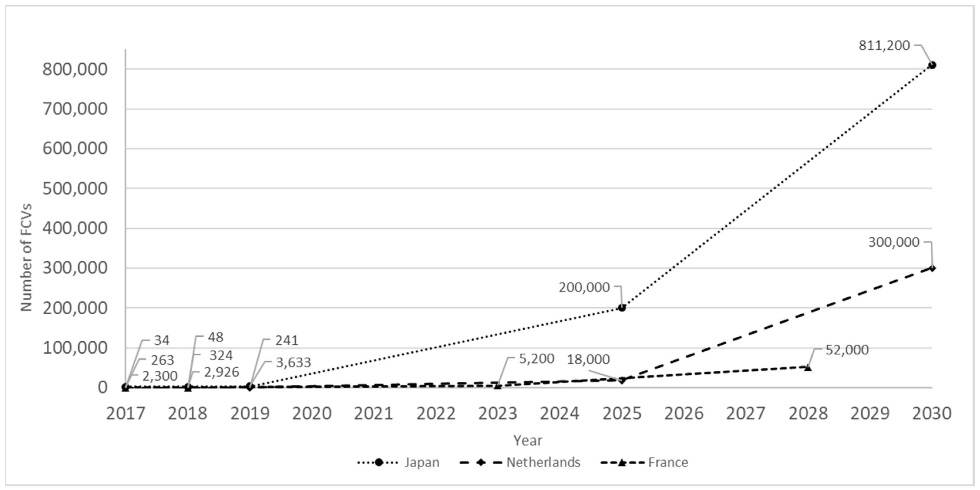
Figure 1. FCVs targets of deployment from 2017 to 2030 for selected exemplar representative countries: Japan, Netherlands, and France [1,7].
Energies 14 04029 g001
Figure 2. Event tree of hydrogen release incident scenarios.
Energies 14 04029 g002
Figure 3. Hydrogen release measurement layout.
Energies 14 04029 g003
Figure 4. CFD model of the hydrogen release layout: (a) single nozzle release, (b) multi-point release.
Energies 14 04029 g004
Figure 5. Experimental and CFD hydrogen concentration results.
Energies 14 04029 g005
Figure 6. Visualization of the hydrogen stratification CFD simulation.
Energies 14 04029 g006
Figure 7. Forced ventilation system parameters.
Energies 14 04029 g007
Figure 8. Visualization of the hydrogen ventilation effectiveness CFD simulation.
Energies 14 04029 g008
Table 1. Hydrogen release parameters [37].
Test No.Hydrogen Release MethodHydrogen Release Outflow [m3/s]Hydrogen Density
[kg/m3]
Hydrogen Mass Flow Rate
[kg/s]
Hydrogen Release Source [m2]Hydrogen Release Velocity
[m/s]
Test 1Single nozzle release 1.63 × 10−30.82 133 × 10−41.256 × 10−5129.78
Test 2Multi-point release 1.63 × 10−30.821.33 × 10−45.935 × 10−42.75
Publisher’s Note: MDPI stays neutral with regard to jurisdictional claims in published maps and institutional affiliations.