Article

An Innovative Sensor for Cable Joint Monitoring and Partial Discharge Localization

Ricerca sul Sistema Energetico RSE S.p.A., Via Rubattino 54, 20134 Milano, Italy
*
Author to whom correspondence should be addressed.
Energies 2021, 14(14), 4095; https://doi.org/10.3390/en14144095
Submission received: 27 May 2021 / Revised: 29 June 2021 / Accepted: 1 July 2021 / Published: 7 July 2021

Abstract

:
To enhance grid reliability, weak points must be monitored. One of the weaknesses is the cable joints, which are prone to failure and can cause great losses from both a technical and economical point of view. Joints failures are usually caused by impurities unintentionally added during installation that cause partial discharges (PDs). In time, these discharges erode the insulation and generate treeing up to a destructive discharge between the conductor and the ground shield. For this reason, a method for the early detection of defects in joint installation and their online monitoring is required. A previously developed sensor was improved by adapting it for this purpose. It is based on the measurement of the induced current on a conductor due to a charge variation. It was experimentally tested on an actual joint in which defects were artificially introduced. Results show that the sensor is able to detect partial discharges. Moreover, a method for PD localization was developed. The first results show a coherency between the possible defect location, numerical simulations and historical background.

1. Introduction

A key factor in the enhancement of electrical grid reliability and early detection of faults is the online monitoring of weak points. For this reason, electrical engineers are currently focused on the development of remote monitoring devices devoted to electrical grid parameters, together with advancements in modeling to address the ageing phenomena. These models are necessary when relevant parameters have to be found for remaining life assessment (RLA) of the device under study and, from there, planning reliability strategies to minimize the outages, which results in energy and economical losses [1,2].
Electrical transmission and distribution are ensured mainly with two distinct types of connection vectors: overhead lines and cables. The first type, much more widespread, has the main disadvantage of a significant environmental impact, together with exposure to atmospheric conditions that results in limited reliability [3,4].
On the other hand, the second type can transmit energy without a substantial modification of the territory but present further weaknesses. Among them, one is the vulnerability of the cable due to the mechanical stresses to which it is subjected [5,6]. Moreover, it is not possible to make cables with lengths greater than certain values due to issues relating to construction and installation. For this reason, to make the electrical connection between two cables, a joint must be placed.
Joint construction is a very delicate operation and is carried out on site by highly qualified workers. As the process is typically performed in cramped environments characterized by the presence of powdery material, joints may be affected by impurities and imperfections that lead, once the line is activated, to deterioration of the insulating material [7,8,9,10,11].
The presence of these defects is the origin of the emergence of micro discharges called partial discharges (PDs). Over time, these discharges erode the insulating material interposed between the conducting core and the external metal screen. This erosion is usually called treeing. Once the defect has crossed the entire insulation, the cable undergoes a destructive discharge, which inevitably leads to the line being taken out of service. The use of current diagnostic techniques, which include both sensors and algorithms, do not allow for localization of defects or consequently their evolution. Therefore, to enhance grid reliability and avoid untimely outages, a method to detect and monitor PD in cable joints is necessary. Recent works propose online monitoring of cable joints [12,13,14,15,16,17,18,19], but they are usually focused on measurements of environmental conditions by monitoring temperature, humidity and sheath currents. Only [13] proposes a sensor for PD monitoring, but it can detect only the induced current without bonding to the source.
Commercially available devices can detect, classify (with machine learning algorithms) and identify the element affected by PD, but only in open air. Moreover, they provide only qualitative parameters (such as the intensity of apparent charge, expressed in Coulombs), which cannot be used as a reliable index of RLA, and it is accordingly difficult to estimate the service life of the device affected by PD. For this reason, the scientific community is focused on improving methods to detect and localize the source of PDs [20,21,22].
This paper proposes a new technique that aims to detect the presence of PD in underground cable joints and provide an estimation of the defect position that generates the PD. An innovative sensor specifically developed for defect localization in axisymmetric geometries was firstly presented by the authors in [23]. The sensor was improved from the prototypal stage of [23] to a standalone sensor able to detect PDs in complex systems such as cable joints. It can be useful for operators during joint construction to assess workmanship. An experimental validation was carried out on two real joints: one realized in a workmanlike manner and the other mechanically stressed to generate partial discharge. Results show that the sensor can detect the defect, if present, and provide a possible locus of the PD.

2. Partial Discharges Monitoring and Sensor Adaption

During joint construction or installation, is it possible to add impurities to the material, such as small air gaps in the insulating material, namely the vacuoles. Usually, they are formed on the irregular contact surfaces of the different materials (conductor, semiconductor, insulator, shielding) or due to mechanical stresses during the placement of the cable.
It is well known that the electric field in a heterogeneous material strengthens passage from areas of high to low dielectric constant. This factor, combined with the small defect volume, increases the electric field in the vacuole. If the electric field in the vacuole exceeds the dielectric strength, a discharge occurs. These discharges (called partial discharges as they do not completely bridge the space between the central conductor and the shield), erode the dielectric material and reduce the service life of the insulator.
In [23], the authors developed a method to detect defects in a homogeneous axisymmetric insulating material due to the induced current on six electrodes mounted on its surface. This approach is based on the concept of the induced current on a conductor given by a moving charge at a certain distance. When a certain number of conductors are placed around the moving charge, the induced currents permit the triangulation of the charge position. In this study, the prototype shown in [23] was improved to be practically implemented for real joints and to monitor partial discharges in multilayer insulating materials.

2.1. Induced Current by a Partial Discharge

It is well known that when an electric charge is moved in a certain region, it induces a current In in a conductor placed at a certain distance:
I n = 0 E ( t t , x ( t ) ) · v ( t ) q ( t ) d t
where q is the intensity of the moving charge, with trajectory x and speed v in the electric field E.
Since the propagation delay is negligible, Equation (1) can be reduced:
I n ( t ) = E n ( x ( t ) ) · v ( t ) q ( t )
A joint exploits a cylindrical symmetry. Therefore, the electric field generated by the central conductor is approximately completely radial, and the charge moves following the electrical field, and thus radially, so Equation (2) can be simplified:
I n ( t ) = E n r ( x ( t ) ) v ( t ) q ( t )

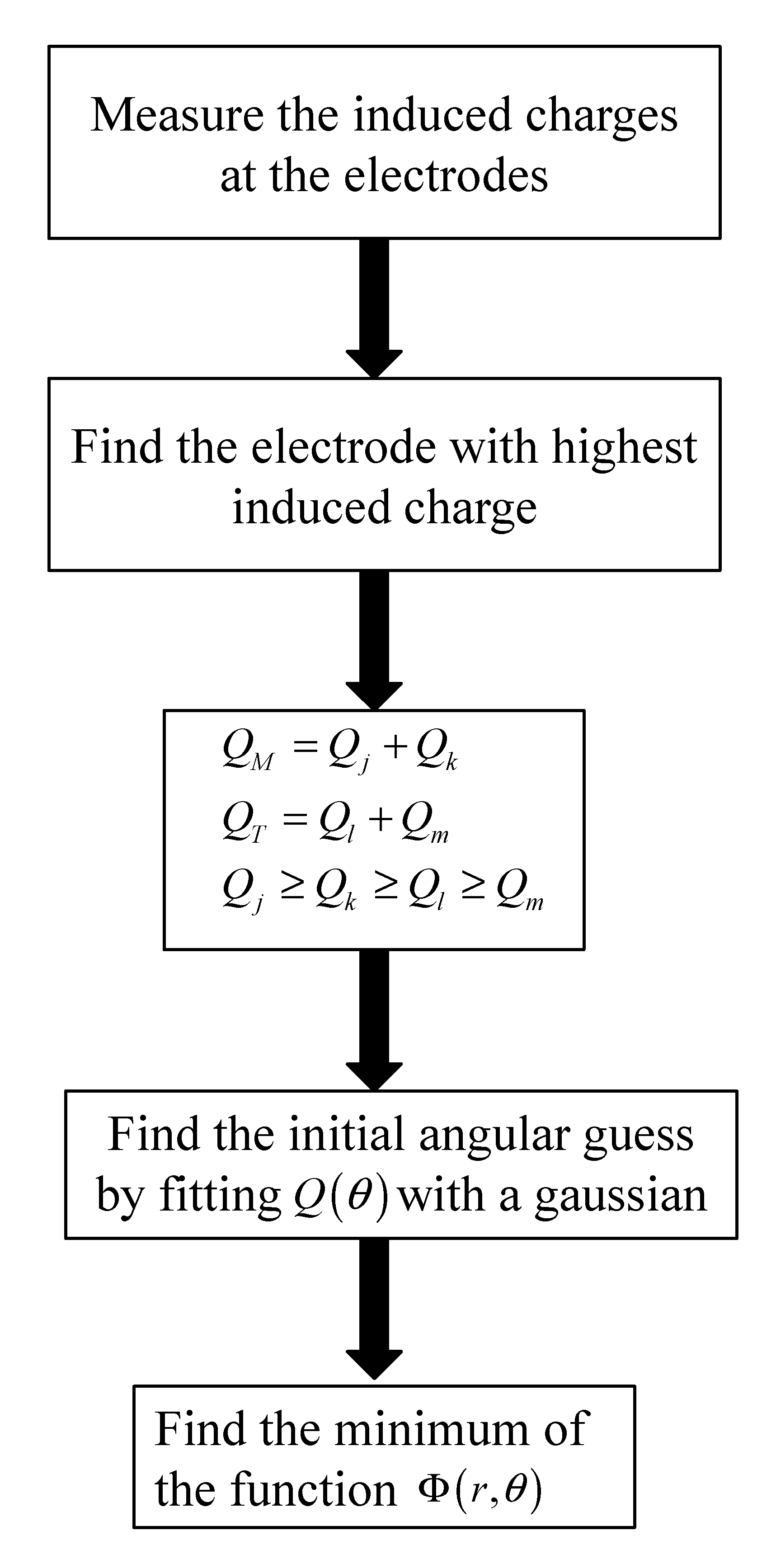
2.2. Localization of a Partial Discharge

As explained in [23], the method for discharge localization starts from the placement of the sensing element all around the surface of the insulating material. This material is composed of N = 6 copper electrodes on which current is induced. Figure 1 provides a 3D view of the PD sensor.
Considering that the movement path of the charge is negligible with respect to the distance between the charge and the sensing element, the charge can be considered still. If one has knowledge of the induced current on an electrode due to a PD in each point of the joint, the problem can be theoretically inverted; measuring the current induced at the electrode, it is possible to locate the possible charge position. Adding more electrodes, more constraints are introduced and the intersection of the different locus of possible charge position returns the guess point; from another point of view, it acts as a triangulation of the signals.
Let us integrate Equation (3) for a generic electrode:
Q n ( t 0 ) = E n r ( r , θ ) d r ( t ) q ( t )
where r and θ are the radial and angular position of the charge. Considering two electrodes, with simple mathematical operations, it can be rearranged:
E j r ( t ) Q j ( t ) E k r ( t ) Q k ( t ) = 0
Following the procedure explained in [23], solving Equation (5) finds the minimum of the function:
Φ ( r , θ ) = 1 2 ( E i r ( r , θ ) Q i ( t k ) E j r ( r , θ ) Q j ( t k ) ) 2 + 1 2 ( E T r ( r , θ ) Q T ( t k ) E M r ( r , θ ) Q M ( t k ) ) 2 ( Q M ( t k ) Q T ( t k ) ) 2
where
E M = E i r + E j r E T = E l r + E m r
The procedure can be summarized as the flux diagram of Figure 2.

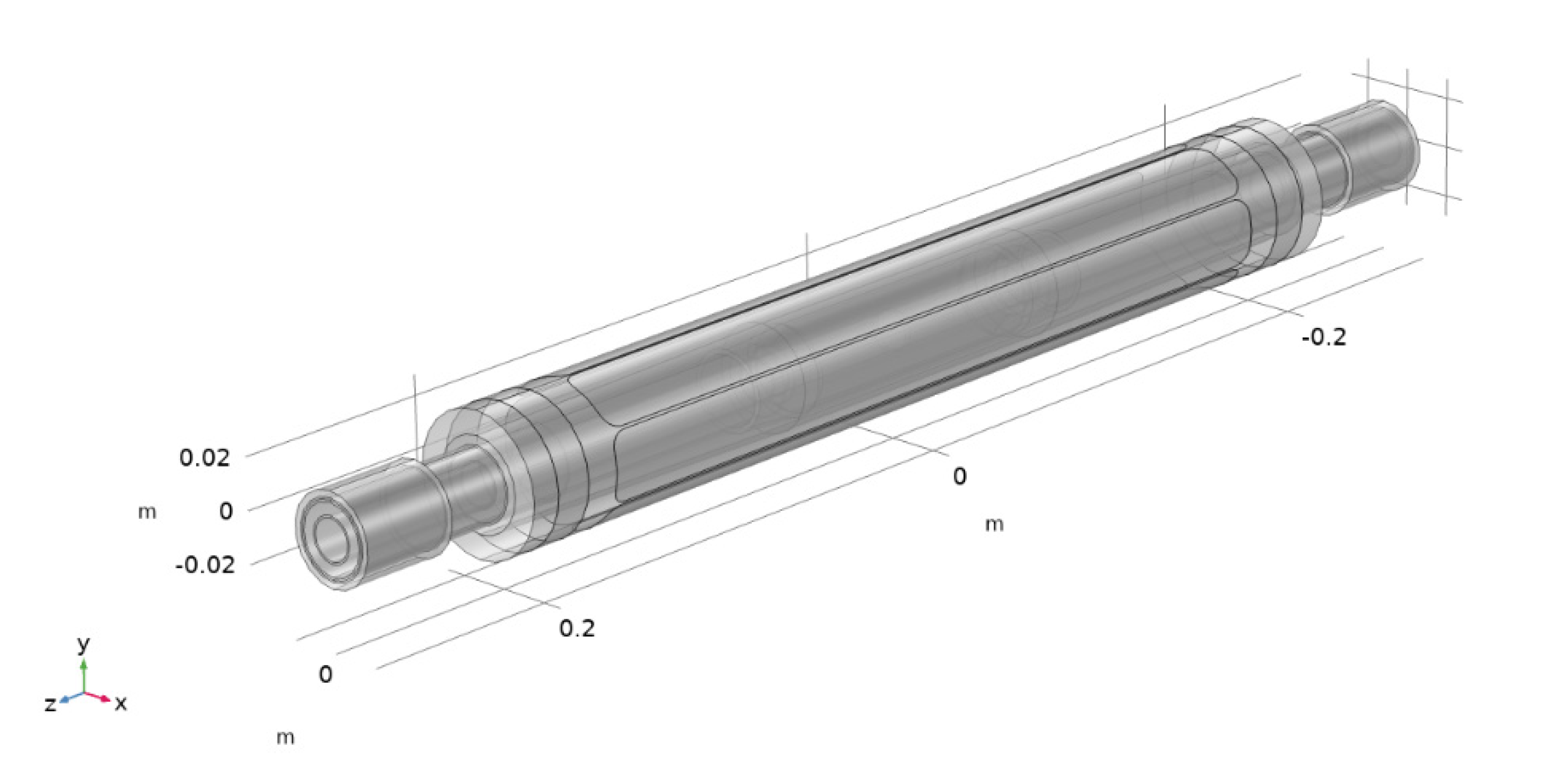
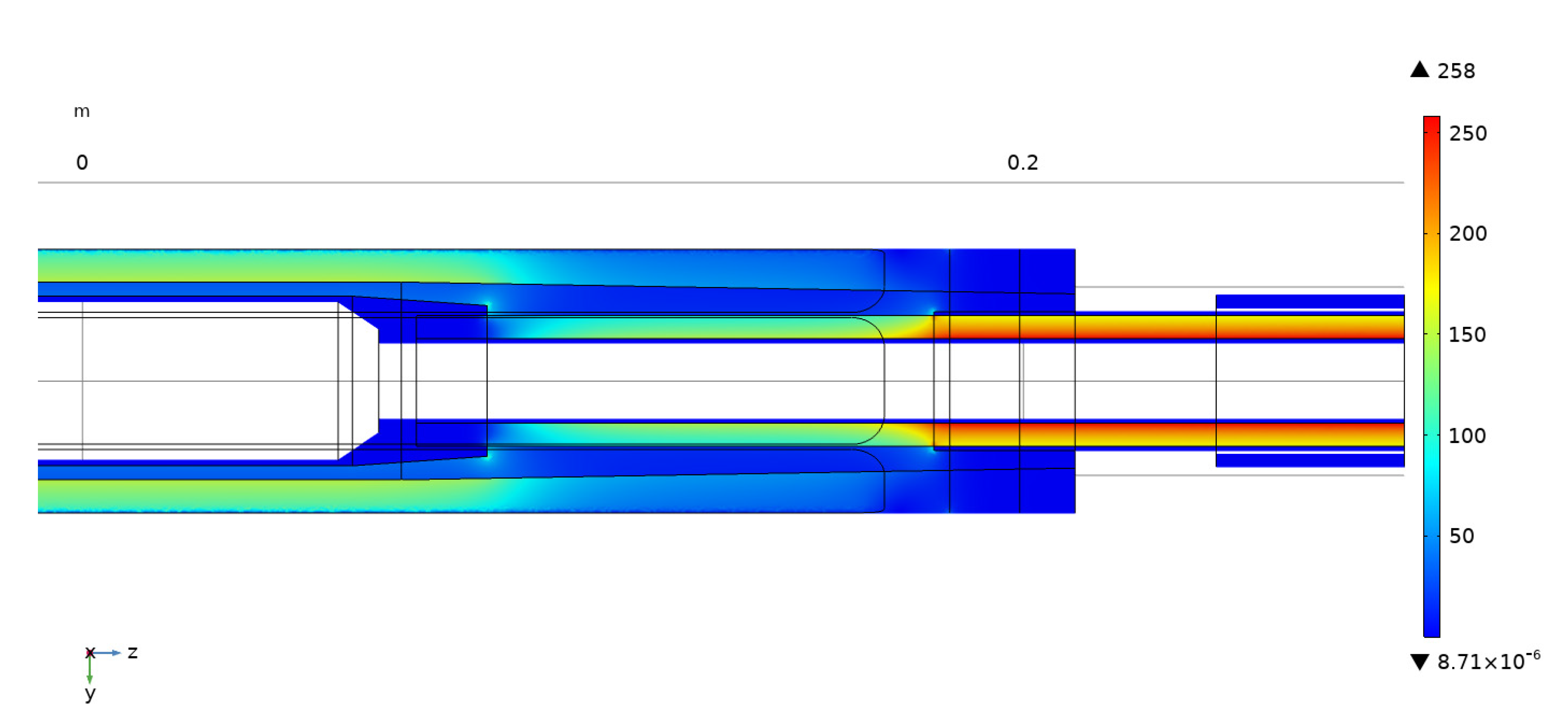
2.3. FEM Simulation on an Actual Joint

The electric field distribution E for the discharge location could be evaluated either by analytical functions or by means of numerical simulations. In [23], the authors used the analytical functions of a homogeneous prototype. In this case, since the real joint is composed of different kinds of materials and does not have a simple geometry, an evaluation of the electric field distribution was performed by means of numerical simulations.
The considered commercial joint is composed of:
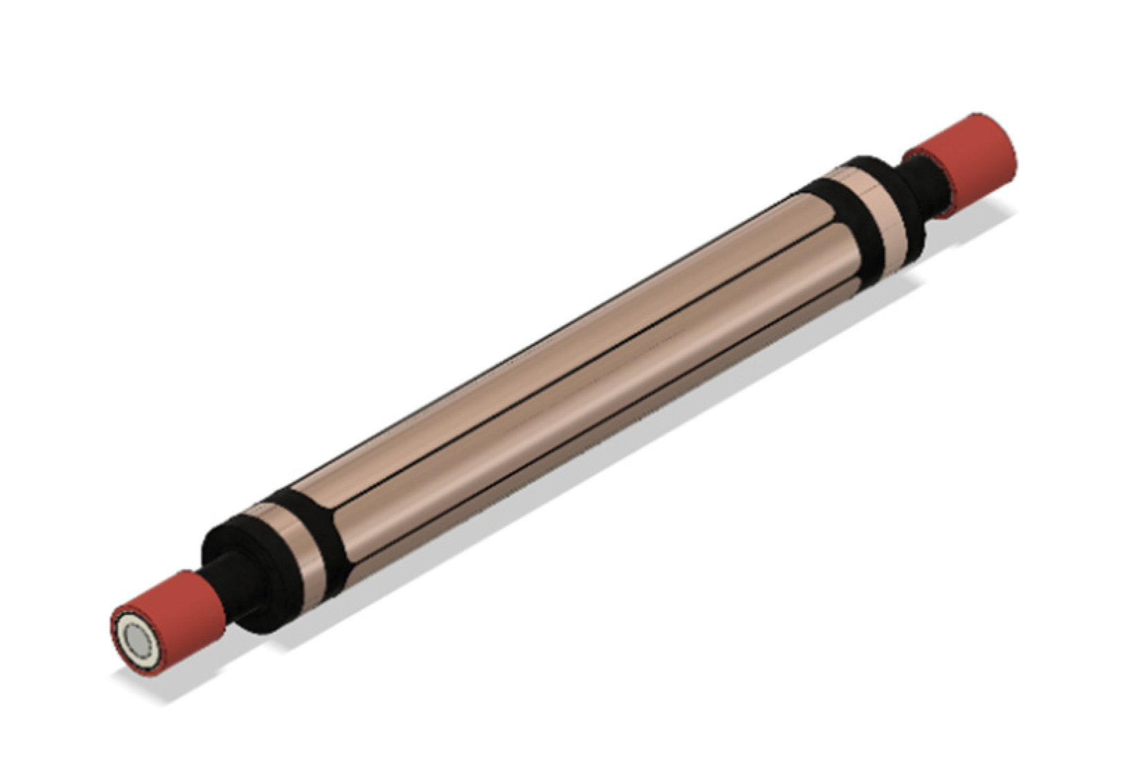
  • A metallic core in which the two cables are clipped together;
  • A semiconductor tape, to ensure uniformity of the field around the cable (εr = 2.8, σ = 3 × 10⁻⁴ S/m) [24];
  • Two dielectric materials, one with high permittivity (εr = 15, σ = 3 × 10⁻¹² S/m) and the other with low permittivity (εr = 3, σ = 5 × 10⁻¹⁵ S/m).
In Figure 3 the different steps of the joint realization are shown.
A hybrid electrostatic and magnetostatic FEM model was developed with the typical physical dimensions of the joint, as shown in Figure 4.
In Figure 5, the results of the simulation of the electric field strength are depicted (cut on the x = 0 axis).
From Figure 5, it can be clearly seen that the electric field strengthens in the untouched part of the cable, up to the external semiconductive area, which results in a voltage next to zero, since it is connected to the metallic shield. Moreover, the high permittivity material around the joint strongly diminishes the electric field, which strengthens in the lower permittivity material, away from the conductive part. Finally, it can be noticed that at the end of the semiconductor tape, the step that is formed locally increases the field.
The basis function was calculated following the procedure explained in [23].

3. Experimental Setup

The sensor was developed along with a set of six copper insulated electrodes, which were bent together on the external surface of the final part of the joint and shaped to be uniformly distributed on the surface of the joint as in Figure 1. These components were insulated from the ground shield using insulating material. Two 16 kV joints were realized: joint #1 was constructed in a workmanlike manner, while joint #2 was mechanically stressed. Two identical sensors were placed just under the ground screen of the joints, as depicted in Figure 6.
In contrast to [23], the signal conditioning and processing were completely reviewed. In this step, the output of the electrodes was connected to an amplification and insulation stage (with a gain equal to 20) and then filtered. Then, the signals were digitalized by means of a Picoscope 4824 and sent to a PC for elaboration and visualization. A block diagram of the measurement system is shown in Figure 7.
The joint was fed by means of a controllable power source (Ametek CSW5550) connected to a step-up transformer (with a gain equal to 227). The output of the transformer was connected to the cable through a filtering and current limiter stage. The other end of the cable was left open. In parallel to the cable, a system for the measurement of the PD according to IEC60270 [25] was used. It consists of a coupling capacitor connected to a quadrupole and then to an Omicron MPD 600. In order to monitor the output of the signal generator, it was measured through a VT (with k = 290) and sent to the Picoscope. The transformer, cable and monitoring system were placed in a Faraday cage in order to limit the noise level. The circuit is summarized in Figure 8.

4. Experimental Results

4.1. Partial Discharge Detection

First of all, joint #1 was tested. A sinusoidal voltage (at 50 Hz) with Vin = 55 V rms was generated by the power source, corresponding to the rated cable voltage, namely 12 kV. All the six channels of the Nabla sensor were acquired with a sampling frequency of fs= 40 MSa/s per channel together with the input voltage from the monitor. Results are provided in Figure 9.
As expected, the output of each electrode was about zero; except for a small fluctuation given by external noise, the sensor does not measure any induced current at the electrodes. In addition, the reference PD measurement tool (the Omicron device) also does not measure any apparent charge. This confirms with a high confidence level that the joint was effectively made without any defects.
Subsequently, joint #2 was placed and connected to the step up transformer. As PDs were expected, a reduced input voltage was firstly set (about 50% of the rated voltage). Again, the output of the six electrodes was acquired together with the input voltage (Figure 10).
As expected, in this case the induced current at the electrodes was far from being zero; a remarkable number of current pulses were measured at the electrodes for each period of the 50 Hz signal. These peaks unequivocally report a non-negligible PD activity in the joint. Conversely, the omicron measurement provides values of around 8 to 10 pC, a value similar to the noise band of the measurement circuit, which was previously measured.
To further explore the results, in Figure 11 the measured voltage of the first peak is shown.
From the figure it can be clearly seen that the induced voltage at electrode #2 has the highest value (more than 80 mV), and this value decreases by moving far (in angular position) from the circular sector defined by electrode #2. Electrodes #3 and #1 showed the second and third highest induced currents, corresponding respectively to 60 and 30 mV peaks. As the current induced in the electrodes is different among them, the element inducing these currents is enclosed in the volume defined by the sensor. The sensor is shielded by external phenomena due to the ground shield of the joint. Moreover, if a current is flowing in the grounding system, it acts uniformly on each electrode. This was also verified via a UV camera for discharge detection (specifically, an Ofil Daycor II).
Finally, the input voltage was set to the nominal voltage and rotated around the joint. As expected, a higher number of PDs were generated, and the values of the measured voltage at the six electrodes varied according to the angular rotation. Figure 12 reports the acquired PD over an observation time of 50 ms.
Focusing again on one PD, the values of the induced currents change according to the given rotation (of about 25°), as depicted in Figure 13.
The induced currents vary significantly from those in Figure 12, according to the relative rotation given between electrodes and joint. Electrode #3 has the highest induction but is similar to electrode #2.
Consequently, measured voltage of electrode #4 is strengthened, as the movement of the sensor reduces the distance between this electrode and the PD location, and induced current of electrode #1 is negligible as it is distanced from the inducing charge.

4.2. Partial Discharge Location

After having measured the impulses of the electrodes, it is possible to locate the source of the induced currents with the procedure explained in [23]. This procedure basically consists of the evaluation of the minimum of the function [6] for the four electrodes with the highest induced charge. As explained before, the electrodes have not been designed to be sensitive to the z-axis; hence, the locus of discharge is not a univocal point but a line on the z-axis. The procedure was followed for all the PD events, and results are shown in Figure 14.
All the detected PDs provide two areas of possible defect location. The first is located between the end of the semiconductor tape used to ensure uniformity of the field (as in Figure 3b) and the primary insulator. This is one of the weak points, as also highlighted by the steady state evaluation of the electric field, as the step between the two materials increases the local field. The second is located at the end of the untouched insulation of the cable, where a small defect in removing the insulation and in the cleaning of the material can be inadvertently added. Due to the geometry of the sensor, it is not possible to discriminate the actual PD location. The same results were found with the original placement of the sensor with a lower voltage.

5. Conclusions

A current objective in enhancing grid performance is increasing reliability. One of the weak points of the transmission and distribution grids is the connection between different cables, namely the joints. Their installation is a difficult task and requires trained technicians to reduce the defects that can be unintentionally added due to the difficult environment in which they operate. The introduced defects can generate partial discharges that, in time, can erode the insulation between the cable and the shield, leading to destructive discharges. For this reason, a method for the early detection and the online monitoring of the joints is necessary. Considering the induced current to an electrode given by a moving charge in a dielectric material, the electric field can be analytically computed as function of the charge position. A previously developed sensor to detect defects in axisymmetric geometries was adapted and improved for partial discharge detection and location of the possible source using a previously presented algorithm. The sensor was validated experimentally with two joints: one made in a workmanlike manner and the other mechanically stressed during the installation. Results show that the sensor is able to detect the partial discharges with a low induced current. Therefore, it permits an early detection of the PD that may evolve into a total discharge. Moreover, the algorithm proposed is able to provide possible areas of defect location and could allow manufacturers and DSOs to address weak points of joints.

Author Contributions

Conceptualization, L.B., A.V. and R.M.; methodology, L.B. and A.V.; validation, L.B., D.P. and C.L.; investigation L.B., D.P. and C.L; resources, R.M.; data curation, L.B. and A.V.; formal analysis L.B and A.V., writing—original draft preparation, C.L.; writing—review and editing, C.L., L.B. and D.P.; supervision, L.B. All authors have read and agreed to the published version of the manuscript.

Funding

This work was partially financed by the Research Fund for the Italian Electrical System in compliance with the Decree of 16 April 2018.

Acknowledgments

The authors would acknowledge the technical support of Unareti in providing and install the joints.

Conflicts of Interest

The authors declare no conflict of interest.

References

  1. Anwar, R.; Pudjiantoro, B.; Bahroinuddin, M. INTRO RLA A Methodology for Assessing the Remaining Life of Major Electrical Equipment to Extend the Service Life beyond the Design in PHE ONWJ. In Proceedings of the IEEE 4th Conference on Power Engineering and Renewable Energy, Solo, Indonesia, 29–21 October 2018; pp. 1–9. [Google Scholar] [CrossRef]
  2. Zaeni, A.; Khayam, U.; Viviantoro, D. Methods for Remaining Life Prediction of Power Cable based on Partial Discharge and Cable Failure History Data. In Proceedings of the 2019 International Conference on Electrical Engineering and Informatics (ICEEI), Bandung, Indonesia, 9–10 July 2019; pp. 662–665. [Google Scholar]
  3. Faifer, M.; Khalil, M.; Laurano, C.; Leone, G.; Toscani, S. Outage data analysis and RAMS evaluation of the Italian overhead transmission lines. In Proceedings of the 2016 IEEE International Energy Conference (ENERGYCON), Leuven, Belgium, 4–8 April 2016; pp. 1–6. [Google Scholar] [CrossRef]
  4. Benato, R.; Napolitano, D. Overall Cost Comparison Between Cable and Overhead Lines Including the Costs for Repair After Random Failures. IEEE Trans. Power Deliv. 2012, 27, 1213–1222. [Google Scholar] [CrossRef]
  5. David, E.; Parpal, L.J.; Crine, J. Influence of mechanical strain and stress on the electrical performance of XLPE cable insulation. In Proceedings of the 1994 IEEE International Symposium on Electrical Insulation, Pittsburgh, PA, USA, 5–8 June 1994; pp. 170–173. [Google Scholar] [CrossRef]
  6. Afia, R.S.A.; Mustafa, E.; Tamus, Z.A. Mechanical Stresses on Polymer Insulating Materials. In Proceedings of the 2018 Electrical Conference on Diagnostics in Electrical Engineering (Diagnostika), Pilsen, Czech Republic, 4–7 September 2018; pp. 1–4. [Google Scholar]
  7. Fabiani, D.; Montanari, G.C.; Laurent, C.; Teyssedre, G.; Morshuis PH, F.; Bodega, R.; Dissado, L.A. HVDC Cable Design and Space Charge Accumulation. Part 3: Effect of Temperature Gradient. IEEE Electr. Insul. Mag. 2008, 24, 5–14. [Google Scholar] [CrossRef]
  8. Zhang, Z.P.; Zheng, C.J.; Zheng, M.; Zhao, H.; Zhao, J.K.; Sun, W.F.; Chen, J.Q. Interface Damages of Electrical Insulation in Factory Joints of High Voltage Submarine Cables. Energies 2020, 13, 3892. [Google Scholar] [CrossRef]
  9. Zhang, Y.; Huang, F.; Hui, B.; Hou, S.; Fu, M.; Xu, Y. Partial Discharge Behavior of 110 kV Silicone Rubber Premoulded Cable Joint Induced by Pre-Expanding Installation and Temperature. In Proceedings of the 2018 Condition Monitoring and Diagnosis (CMD), Perth, WA, Australia, 23–26 September 2018; pp. 1–4. [Google Scholar] [CrossRef]
  10. Yang, F.; Liu, K.; Cheng, P.; Wang, S.; Wang, X.; Gao, B.; Fang, Y.; Xia, R.; Ullah, I. The Coupling Fields Characteristics of Cable Joints and Application in the Evaluation of Crimping Process Defects. Energies 2016, 9, 932. [Google Scholar] [CrossRef] [Green Version]
  11. Lowczowski, K.; Lorenc, J.; Tomczewski, A.; Nadolny, Z.; Zawodniak, J. Monitoring of MV Cable Screens, Cable Joints and Earthing Systems Using Cable Screen Current Measurements. Energies 2020, 13, 3438. [Google Scholar] [CrossRef]
  12. Steennis, F.; Wagenaars, P.; van der Wielen, P.; Wouters, P.; Li, Y.; Broersma, T.; Harmsen, D.; Bleeker, P. Guarding MV cables on-line: With travelling wave based temperature monitoring, fault location, PD location and PD related remaining life aspects. IEEE Trans. Dielectr. Electr. Insul. 2016, 23, 1562–1569. [Google Scholar] [CrossRef] [Green Version]
  13. Peretto, L.; Foddai, L.; Orrù, S.; Puddu, L. New MV Cable Accessory with Embedded Sensor to Check Partial Discharge Activity. In Proceedings of the 23rd conference on Electricity Distribution (Cired), Lyon, France, 15–18 June 2015. [Google Scholar]
  14. Mingotti, A.; Ghaderi, A.; Mazzanti, G.; Peretto, L.; Tinarelli, R.; Valtorta, G.; Amoroso, G.; Danesi, S. Low-Cost Monitoring Unit for MV Cable Joints Diagnostics. In Proceedings of the 2018 IEEE 9th International Workshop on Applied Measurements for Power Systems (AMPS), Bologna, Italy, 26–28 September 2018; pp. 1–5. [Google Scholar] [CrossRef]
  15. Testa, L.; Cavallini, A.; Montanari, G.C.; Makovoz, A. On-line partial discharges monitoring of high voltage XLPE / fluid-filled transition joints. In Proceedings of the Electrical Insulation Conference, Annapolis, MD, USA, 5–8 June 2011. [Google Scholar]
  16. Xianbo, M.; Xiaoguang, H. Design of on-line temperature monitoring system for power cable joints based on supercapacitor. In Proceedings of the 10th IEEE International Conference on Industrial Informatics, Beijing, China, 25–27 July 2012. [Google Scholar]
  17. Dong, X.; Yuan, Y.; Gao, Z.; Zhou, C.; Wallace, P.; Alkali, B.; Sheng, B.; Zhou, H. Analysis of cable failure modes and cable joint failure detection via sheath circulating current. In Proceedings of the Electrical Insulation Conference, Philadelphia, PA, USA, 8–11 June 2014. [Google Scholar]
  18. Jongen, R.; Gulski, E.; Smit, J. Failures of medium voltage cable joints in relation to the ambient temperature. In Proceedings of the 20th International conference and Exhibition on Electricity Distribution, Prague, Czech Republic, 8–11 June 2009. [Google Scholar]
  19. Christou, S.; Lewin, P.L.; Pilgrim, J.A.; Swingler, S.G.; Geoprghiou, G.E.; Makrides, G.; Stavrou, A.; Evagorou, D. Setup and preliminary results of an online thermal condition monitoring system for MV cable joints. In Proceedings of the 18th Mediterranean Electrotechnical Conference (MELECON), Lemesos, Cyprus, 18–20 April 2016; pp. 1–4. [Google Scholar] [CrossRef]
  20. Khan, U.F.; Lazaridis, P.I.; Mohamed, H.; Albarracín, R.; Zaharis, Z.D.; Atkinson, R.C.; Tachtatzis, C.; Glover, I.A. An Efficient Algorithm for Partial Discharge Localization in High-Voltage Systems Using Received Signal Strength. Sensors 2018, 18, 4000. [Google Scholar] [CrossRef] [PubMed] [Green Version]
  21. Azadifar, M.; Karami, H.; Wang, Z.; Rubinstein, M.; Rachidi, F.; Karami, H.; Ghasemi, A.; Gharehpetian, G.B. Partial Discharge Localization Using Electromagnetic Time Reversal: A Performance Analysis. IEEE Access 2020, 8, 147507–147515. [Google Scholar] [CrossRef]
  22. Mas’ud, A.A.; Ardila-Rey, J.A.; Albarracín, R.; Muhammad-Sukki, F.; Bani, N.A. Comparison of the Performance of Artificial Neural Networks and Fuzzy Logic for Recognizing Different Partial Discharge Sources. Energies 2017, 10, 1060. [Google Scholar] [CrossRef] [Green Version]
  23. Villa, A.; Barbieri, L.; Malgesini, R. Precise partial discharge localization in axisymmetric geometries. IEEE Trans. Dielectr. Electr. Insul. 2020, 27, 606–612. [Google Scholar] [CrossRef]
  24. Scotch Electrical Semiconducting Tape 13. Available online: https://multimedia.3m.com/mws/media/41134O/scotch-electrical-semi-conducting-tape-13.pdf (accessed on 15 May 2021).
  25. International Electrotechnical Commission. High-Voltage Test Techniques—Partial Discharge Measurements; IEC 62070:2000+AMD1:2015; IEC: Geneva, Switzerland, 2015. [Google Scholar]
Figure 1. 3D render of the PD sensor.
Energies 14 04095 g001
Figure 2. Flowchart of the localization procedure of the partial discharges.
Energies 14 04095 g002
Figure 3. Joint realization steps: (a) metallic core; (b) semiconductor tape around the core; (c) dielectric material.
Energies 14 04095 g003
Figure 4. Joint physical dimensions.
Energies 14 04095 g004
Figure 5. Electric field simulation of the joint.
Energies 14 04095 g005
Figure 6. Placement of the PD sensor and the ground shield on the joint.
Energies 14 04095 g006
Figure 7. Block diagram of the measurement system.
Energies 14 04095 g007
Figure 8. Equivalent circuit of the test circuit.
Energies 14 04095 g008
Figure 9. Measured voltage from the monitor and the electrodes, joint #1.
Energies 14 04095 g009
Figure 10. Measured voltage from the monitor and the electrodes, joint #2.
Energies 14 04095 g010
Figure 11. Measured voltage at the electrodes during a PD.
Energies 14 04095 g011
Figure 12. Measured voltage from the monitor and the electrodes, joint #2 (at nominal voltage).
Energies 14 04095 g012
Figure 13. Measured voltage at the electrodes during a PD (at nominal voltage).
Energies 14 04095 g013
Figure 14. Voltage measured by the electrodes during rge.
Energies 14 04095 g014
Publisher’s Note: MDPI stays neutral with regard to jurisdictional claims in published maps and institutional affiliations.

