Article

Personalized Anti-Vibration Protection for Telematics Devices in Urban Freight Transport Vehicles

Department of Technological Processes, Faculty of Economics and Transport Engineering, Maritime University of Szczecin, ul. Wały Chrobrego 1-2, 70-500 Szczecin, Poland
*
Author to whom correspondence should be addressed.
Energies 2021, 14(14), 4193; https://doi.org/10.3390/en14144193
Submission received: 23 April 2021 / Revised: 8 July 2021 / Accepted: 9 July 2021 / Published: 11 July 2021
(This article belongs to the Special Issue High Efficiency Electric Freight Vehicle)

Abstract

:
Vibrations are a major cause of human health disorders, circuit boards and machinery damage. Vibration dampers are considered to be the best option to counter these issues. Three-dimensional printing techniques play an increasingly important role in manufacturing small polymer parts with tailored properties. Thermoplastic elastomers (TPE) constitute a perfect material for manufacturing small-scale series absorber prototypes due to their thermoplastic nature, good elasticity and damping properties. This paper proposes a novel multi-level approach to the design and manufacturing process, e.g., the first level—selection of material; second level—decision about the geometry of a damper; third—selection of technological printing parameters; fourth—post-printing treatment. This work primarily aims to overview the design and manufacturing process levels. The impact of each step on the damping capacity of small absorbers is assessed. It was found that thermoplastic elastomers and fused deposition modeling (FDM) have huge potential in shaping the physical properties of small, elastomeric absorbers. It was assessed that at every step of the multilevel design and manufacturing process (MDMP), the designer could tailor the damping to meet the desired criteria of a final product: a cylinder-shaped hollow damper that can be made from TPE polymer without post-printing treatment and is characterized by good damping.

Graphical Abstract

1. Introduction

1.1. Electric Vans in City Logistics

The usefulness of electric vans in city logistics systems has been indisputably demonstrated in numerous publications [1,2,3,4]. Due to the characteristics of the drive system, such as:
  • A high torque, available over the entire speed range;
  • A low level of noise;
  • No emissions during stoppages associated with the delivery;
  • The easy implementation of systems with simultaneous all swivel and all driven wheels (all-wheel steer–all-wheel drive), which increases maneuverability;
these vehicles are particularly useful for handling the so-called last mile.
As shown in numerous publications, e.g., [5,6,7], trucks and vans are exposed to a number of factors that cause vibrations. In particular, irregularities of roads and their surface condition are indicated as the source of vibrations.
Since the last mile of the supply chain takes place on local and internal roads, often with elements that slow down the traffic, the vehicle is exposed to vibrations and shocks (Figure 1).
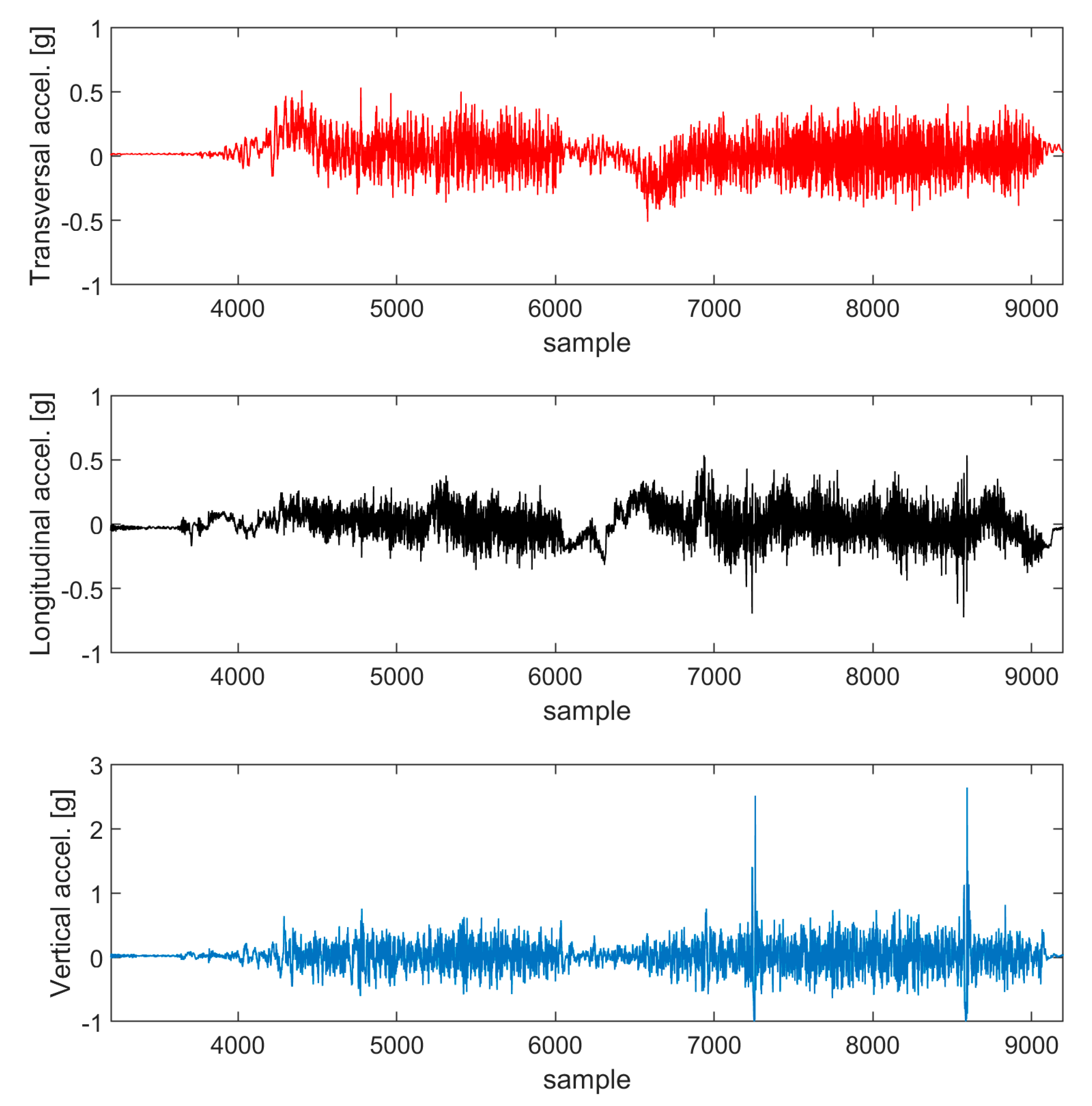
An exemplary course of the components of vibrations of a delivery truck, recorded with the use of accelerometers located in the cargo space, is shown in (Figure 2).
As you can see, the handling of last mile shipments, during which vertical accelerations can reach 3 g, is not uncommon. In combination with longitudinal and transverse accelerations of 0.5 g, we obtain conditions in which the elements of the vehicle control electronics are exposed to the harmful influence of vibrations [8,9,10]. The importance of the problem of the reliability of electronic systems in vibration conditions is confirmed by the standardization of test methods, e.g., MIL-STD-750 [11] and MIL-STD-883 [12].
The above facts are important prerequisites for the development of vibration isolation systems for the protection of electronic components in electrically driven vans.

1.2. Adverse Effect of Vibrations

Mechanical vibrations cause many adverse phenomena in areas such as human work or activities and machine engineering. The major sources of vibrations include machine part damage, the imbalance of rotating machine parts, structural weakness and ill-designed mechanical systems.
Loosened bolt connections, damaged electrofusion welded connections and construction cracks are often a consequence of vibrations. If the material is subject to vibrations of an ultrasonic frequency range, the result is excessive material hardening or softening. Another adverse phenomenon is material fatigue. For example, turbine wheel parts of a 13K215 electric generator can be damaged by vibrations, resulting in the permanent deflection of the rotor shaft and cracks in the rotor structure [13] (pp. 383–434).
Vibrations can generate the following disorders in the human body: episodes of nervousness, fatigue and insomnia. Additionally, vibrations in the low-frequency range are a serious threat to human body, e.g., elastic natural connections between internal organs can be easily damaged if one is subjected to the vibrations mentioned above (the natural frequency of internal organs is 2–18 Hz). Vibrations also affect the circulatory, nervous and osteoarticular systems, damage and cause pain in the lumbar region of the spine and may be a source of degenerative diseases of the osteoarticular system [14]. Hence, a lot of attention and care is needed to appropriately protect personnel against mechanical vibrations.
Authors of publication [15] point out that the person driving the van under increasing vibration conditions will experience three types of adverse effects. These are the physical, physiological and psychological effects, which include instances of tired eyes, absent-mindedness, irritation, and to a lesser degree, the loss of patience, headache, backache, dizziness and nausea. This issue is significant when driving a delivering van over cobblestone roads, as it has a negative effect on the safety of both the cargo and the driver.

1.3. Telematics in Road Transport

In road transport, telematics are classified as follows:
  • Infrastructural;
  • In-vehicle;
  • Mixed.
In-vehicle and mixed telematics belong to in-vehicle computers, such as a Global Positioning System (GPS) and Radio Frequency Identification (RFID), which are a base of complex freight transport management systems. Out of many telematics systems, one can highlight computerized vehicle routing and scheduling or navigation systems and Traffic Control. For example, computerized vehicle routing and scheduling can result in time savings of 10 to 15%, and the GPS gives the driver more flexibility and increases the speed of deliveries. Telematics have an impact on three major areas: social (a decreasing number of accidents), economic (a fixed and operating costs reduction) and environmental (a demand for energy or lowering pollution emissions, mainly CO2 and NOx) [16] (pp. 50–55). Without such systems, the efficiency and functioning of urban freight transport would stay at low level.

1.4. Damping and Dampers

A damper (or absorber) is a device that reduces vibrations that oscillate the motions of an object by lowering the vibration amplitude. Damper structures vary from one type to another. Dampers can operate in two modes: active—with active electrorheological elements (e.g., magnetorheological fluid and electrical circuit) and passive—without such elements [17,18].
Available on the market are semi-active and active dampers, which have a better ability to adjust damping to a specific use than passive dampers. Passive dampers, however, are cheaper, and their damping performance is sufficient for many everyday applications.
The damping of a system, or material, is characterized by different physical parameters, details of which can be found in these works: [19] (pp. 397, 411–412), [20] (pp. 5–6). Hysteresis [21] (pp. 380–390) and the loss tangent (tan δ) [19] (p. 411) are the most often used. The higher the tan δ value, the more the energy is dissipated in one cycle of deformation in the given temperature–frequency conditions. Likewise, the higher the hysteresis value, the more the energy is dissipated in one loading–unloading cycle.
Active dampers are used in buildings, where, depending on external conditions, such as vibrations of the foundation due to e.g., earthquake, damping characteristics are adjusted in order to obtain the best vibration amplitude decrease. An example of passive dampers with viscous damping media is a buffer (an elastomeric damper used in trains), in which elastomer in a steel cylinder is compressed recurrently. Other examples include:
  • Sandwich structures that comprise of steel plates and elastomer between the plates, where elastomer is sheared [18];
  • Solid of revolution shape dampers, where elastomer is compressed [22];
  • Oval Leaf Spring-type structures, where the material of a damper is bent [23].
Although passive dampers have been in use for many years, some issues have not yet been clarified, such as the dependence of damping characteristics on the damper structure and geometry.

1.5. Additive Manufacturing (AM) and FDM Method

The terms additive manufacturing and 3D printing are commonly used in literature interchangeably. Additive manufacturing techniques have been widely discussed in the literature:
  • VAT photopolymerization [24,25,26];
  • Powder bed fusion [24,25,26];
  • Sheet lamination [25,27];
  • Material extrusion, including FDM/fused filament fabrication (FFF) [24,25,26,28].
However, this paper addresses only material extrusion—FDM/FFF. In the present paper, the term FDM will represent both FDM and FFF; the Wohlers report does likewise [27].
FDM is a material extrusion technique, where plastic material—filament in the form of a thin wire (approximately 1.75 mm or 3.00 mm in diameter)—is wound on a spool. It is fed mechanically into the extrusion print head by a set of two counter-rotating grooved cylinders or gears. The polymer is heated, melted and extruded onto the previous layer of polymer, or the printing bed, through the nozzle, which is positioned relative to a heated platform using computer software. The polymer layers are fused. The printing bed is lowered by a given value. After printing and removing the raft, the element is instantly ready to use.
FDM processing temperature, in general, vary between 100 °C (for soft ethylene vinyl alcohol (EVA) polymer [29]) and 315 °C (for stiff acrylonitryle–butadiene–styrene (ABS) [30]). The deposition temperature also depends on the filament chemical makeup.
The FDM method is widely applied in medicine [31,32], mechanical engineering and construction [33,34,35,36]. For electrical engineering applications [37,38], it seems that the use of the FDM technique in printing soft material parts and their mechanical properties has not been fully explored yet.
In the small-scale production of parts–prototypes using AM methods that are below 100 units, the lead time is comparable to other production techniques. The cost of production of the single part is six times lower than for injection molding [39]. Owing to its low cost, FDM is an available technique for many groups of researchers and entrepreneurs worldwide, who contribute to FDM method development and 3D printing knowledge dissemination. It is also worth pointing out that since the year 2000, FDM has been the most commonly used AM method worldwide. The worldwide thermoplastic elastomers demand is increasingly rising and in 2014 it was estimated to be at 4,200,000 tons [40] (p. 7).
The FDM printing speed is related to the material chemical structure (polymer crystallization speed). The anisotropy of the mechanical properties of the produced items is also an important factor to consider [29,41].
Moreover, the FDM printing method enables the manufacturing of soft [29] or very stiff parts [33]. Despite disadvantages, e.g., high-quality filament extrusion in filament fabrication step, a printing speed that depends on the material and a low-resolution printing technique compared to other AM methods, the FDM printing technique still retains flexibility. It is understood as the method that is susceptible to changes in the different levels of polymer parts manufacturing [41].

1.6. Polymers and Thermoplastic Elastomers

Polymers, which are basic engineering materials, have many advantages, such as a low density, good toughness to density ratio, low price per kilogram of material, very good shape mapping capability and good chemical resistance. Common applications of plastics include dampers, which are low hardness polymers/elastomers, household appliances, pipes and small gears, which are medium toughness polymers, sports car bodies and wind turbines external parts, which are very stiff polymer/composites and many more. However, new cutting-edge polymers, with better mechanical and physicochemical properties, are being developed every day.
The market offers many types of polymers that can be used for the fabrication of 3D printing filaments. Many materials that fit for injection molding can be used in the FDM printing process. Prints, as well as injection molded parts, can be further heat-treated or subjected to initial mechanical deformation. This makes adjusting print properties to specific operating conditions possible.
Polymers used in 3D printing using the FDM method are divided in three groups: high stiffness polymers [33,36,42,43,44,45,46,47], average to low stiffness polymers [29,37,38,48,49,50] and support materials [43].
Beside standard filaments, references indicate composites as printing material [35,43,47]. The market also offers other filaments with special properties: see [43,51,52].
Detailed information about the damping of polymers and tan δ parameter can be found in works [53,54,55]. Attention should be given to the fact that elastomers have the highest damping capacity.
TPEs constitute a group of polymers that can withstand a large strain without breaking (several hundred per cent) and have a high impact resistance. Compared to other engineering polymers, TPEs have a low hardness and very good damping capacity. TPEs are also recyclable and easily processed by injection molding or extrusion [40].
TPEs can be divided into: TPE-S (styrene hard segment), TPE-V or TPV (dynamically vulcanized TPEs), TPE-O (TPEs with polyolefin soft and/or hard segment), TPEs consisting of halogenic derivatives of polyolefins and rubber, TPE-U, TPE-A (amide hard segment), TPE-E and other TPEs [40] (p. 3). The most important of the above mentioned are TPE-S, TPE-U and TPE-E due to their good mechanical properties. There are also other types of thermoplastic polymers that have good mechanical properties, such as EVA. This polymer is worth mentioning at this point but is not addressed in this paper.
Researchers often use TPEs and block copolymers in order to produce mechanical [29,37,38,48] and electrical test samples [38] and various prototypes [37,49,56,57].
However, the present knowledge shows that thermoplastic elastomer filaments have not gained enough popularity among researchers that deal with damping protection [58] (pp. 81–98).

1.7. Manufacturing Process Management (MPM)

Designer and printing technologies have to keep to specific algorithms or printing process methodology in order to keep the highest printed part quality.
Layman in printing usually uses a simplified approach to the printing process, which comprises of two steps: the selection of material to print and the selection of geometry of a printed part. Designers and technologists have to be aware of the fact that there are more steps than those mentioned above and that they affect print quality to a high degree [59].
In the work [41], researchers present a “materials and process selection protocol”. It is comprised of the following elements:
  • Selection of material;
  • Selection of (print) parameters;
  • Printing;
  • Evaluation—printability and properties;
In reference [59], authors present a different approach to the print production process:
  • Pre-process, encompassing steps such as product development, design, material selection, material composition, slicing and deposition strategy;
  • In-process: loading of material, liquification, pressure, extrusion, plotting, bonding and support;
  • Post-process: component cooling, support removal, mechanical finish and chemical finish.
The protocols mentioned above lack an in-depth analysis of each step. They do not explain how each step contributes to the damping of prints made of thermoplastic elastomer material. Therefore, we propose a modified protocol that designers or technologists may use in the design process of prototype fabrication.
With regards to [41] approach, the first step, which was the selection of material, was discussed in more detail. We added the “geometry of a print” as a second step. The third step, “printing”, was replaced with “selection of technological parameters”. The fourth step, “evaluation—printability and properties”, was replaced with “post-printing treatment”. We explained how post-printing treatment is related to the properties of a print. The fifth step was “result”, which was the quality assessment of a fabricated print (Figure 3).

1.8. Summary—Need of the Study

According to our literature review, there is a lack of works that link additive manufacturing, thermoplastic elastomer filaments, the 3D printing FDM method and the production of small-scale dampers (damping phenomenon). An element of novelty is also the use of additive manufacturing in the quick production of parts designed for urban freight transport and telematics. It is also worth noting that technologies presented in this work can eliminate the production of very costly injection molds.
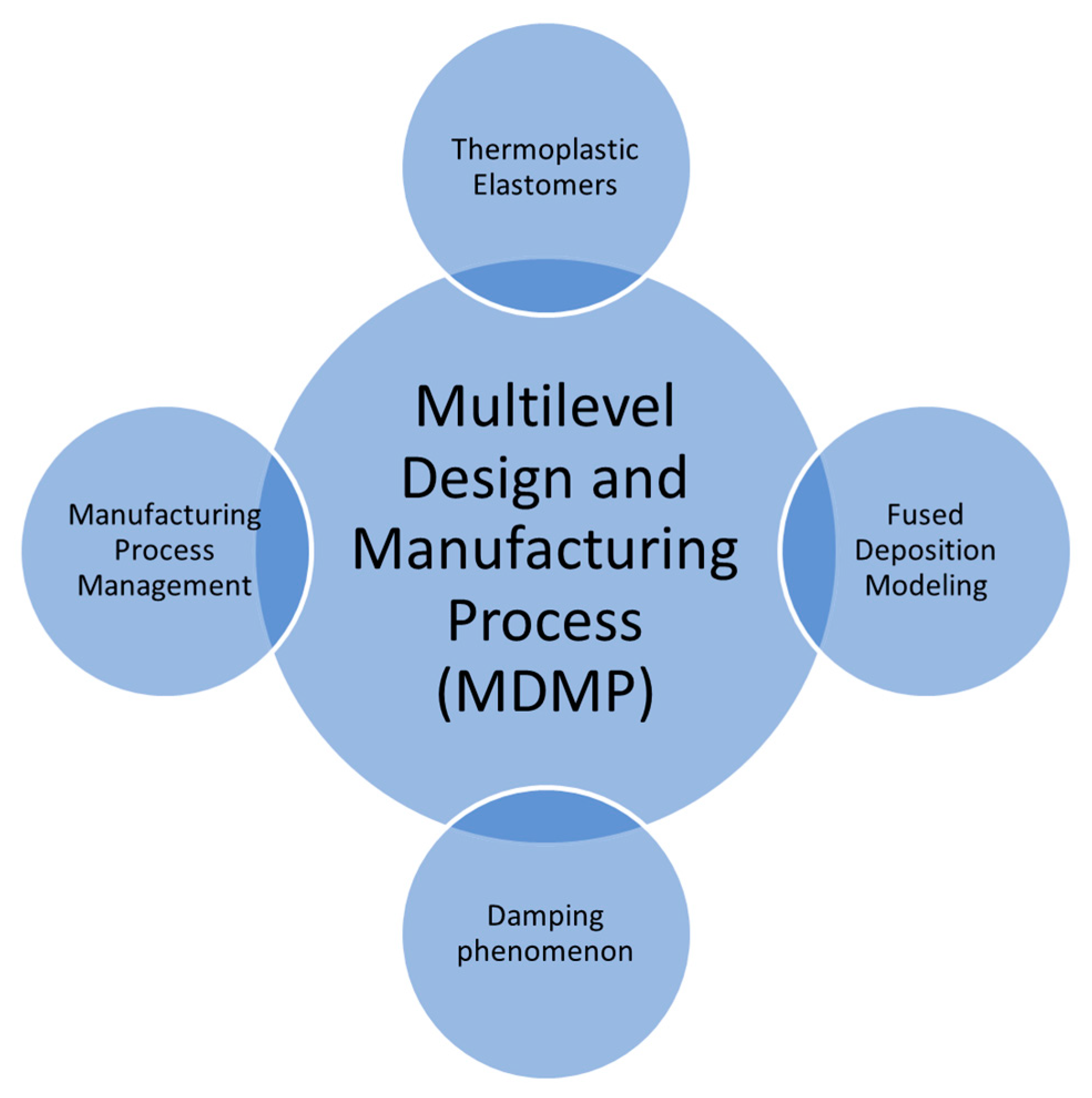
Based on the data and information given above, we can formulate a thesis that in urban freight transport there is a need to provide telemetric devices and appropriate vibration protection for the human body. In order to adjust vibration to a specific application, one can use the multilevel design and manufacturing process protocol presented in this work. Damping absorbers can be readily produced using the FDM method and elastothermoplastic filament (Figure 4).
It is essential to adjust the design process to make it more predictive in avoiding sources of vibrations in mechanical systems. The effects of decreased vibrations, i.e., lower amplitudes, in the mechanical system, should translate into producing parts of higher quality, lower machine failure rate and better health and comfort of workers at places exposed to vibrations.
The relationship between the damping and micro- and macrostructure of absorbers produced using additive manufacturing methods needs to be clarified.

2. Materials and Methods

2.1. Vibration Test

Vibrations caused by roadway failures are measured by accelerometers in vehicle modules or simply in driver’s smartphone. That data can then be transferred to vehicle microcontroller and further analysed. Work [60] presents simple approach. Using smartphone or other device, such as iPad, with accelerometers, transversal, longitudinal and vertical components of acceleration were recorded. Values of transversal component of acceleration represent turning or rocking of vehicle body, longitudinal values represent accelerating or slowing down of a vehicle, vertical values represent vertical movements of vehicle body. Using this simplified approach, authors of present publication recorded dataset of three acceleration components, which were analyzed afterwards.
Discussion on the sensors embedded in mobile devices is given in number of publications, including biomechanics in the field of health sciences [61,62,63], geology and geophysics [64,65], which includes a technical description of software intended to make tests in the field of vibroacoustics.
This discussion indicates that accuracy of sensors varies from group to group. In particular, authors of works [64,65] are critical when dealing with stability and accuracy of magnetometers and clinometers. They suggest to compare the reading of device with other analogue devices very often. In turn, publications [61,62,63] point out good correlation of mobile accelerometer readings with those used in clinical research. Robert Bosch GmbH uses mobile devices embedded sensors to vibroacoustic measurements [66].
Authors of present work assumed measuring range of accelerometers in 4th generation iPad to be 2 g, i.e., approximately 20 m/s2 at 0.1 m/s2 measurement accuracy. These parameters are in line with data from specialistic websites, e.g., Phyphox [67]. Official data on sensors used in iPad device are not available to general public.
The aim of present publication was to develop simple and initial methodology to test the damping of small vibroisolators. Thus, freely available mobile devices were used. Using the high precision accelerometers in a calibration and testing procedure is intended in the next step of the research. In particular, fragile shipments delivery monitoring 5G telematics and their resistance to vibrations will be researched.
Vibration-inducing device was mechanical sieve shaker Morek Multiserw type LPzE-2e, with excitation frequency 50 Hz. Dampers were glued to the sieve shaker using double-sided 0.2 mm thick tape (Figure 5). Afterwards, iPad was attached to dampers using the same manner as mentioned above.
Data registration in vibration tests: iPad commercial device with Matlab Mobile, sampling rate 100 Hz, accelerometers work in +/−20 m/s2 (2 g) acceleration range, 8 bit resolution. For each sample three amplitudes: 0.5 mm, 1 mm and 1.5 mm, were used and three acceleration components were recorded.
Peak-to-peak amplitude for each dataset in experiment (Table 1) was then calculated. Damping was calculated by dividing amplitude peak-to-peak for each sample by amplitude for system without dampers.

2.2. Printing Parameters and Conditions

Small-scale absorbers used to determine stress–strain curve and relationship between max compression strain in one cycle and energy dissipated, were fabricated with use of MakerBot Replicator 2X printer. Authors used following filament: 1.75 mm in diameter, 3D UNIVERSAL filament known under the name UNIFLEX 75®. This filament had hardness of 75 Shore A and elongation at break 650%. Printing parameters: absorber geometry = cylinder 10 mm high and diameter 12 mm, infill type = linear, infill density = 0%, 50% and 100% (see Table 1), printing temperature = 245 °C, cooling fan speed = 100%, layer height = 0.2 mm and number of shells (walls) = 3. Slicer software was provided by MakerBot Replicator 2X printer manufacturer.
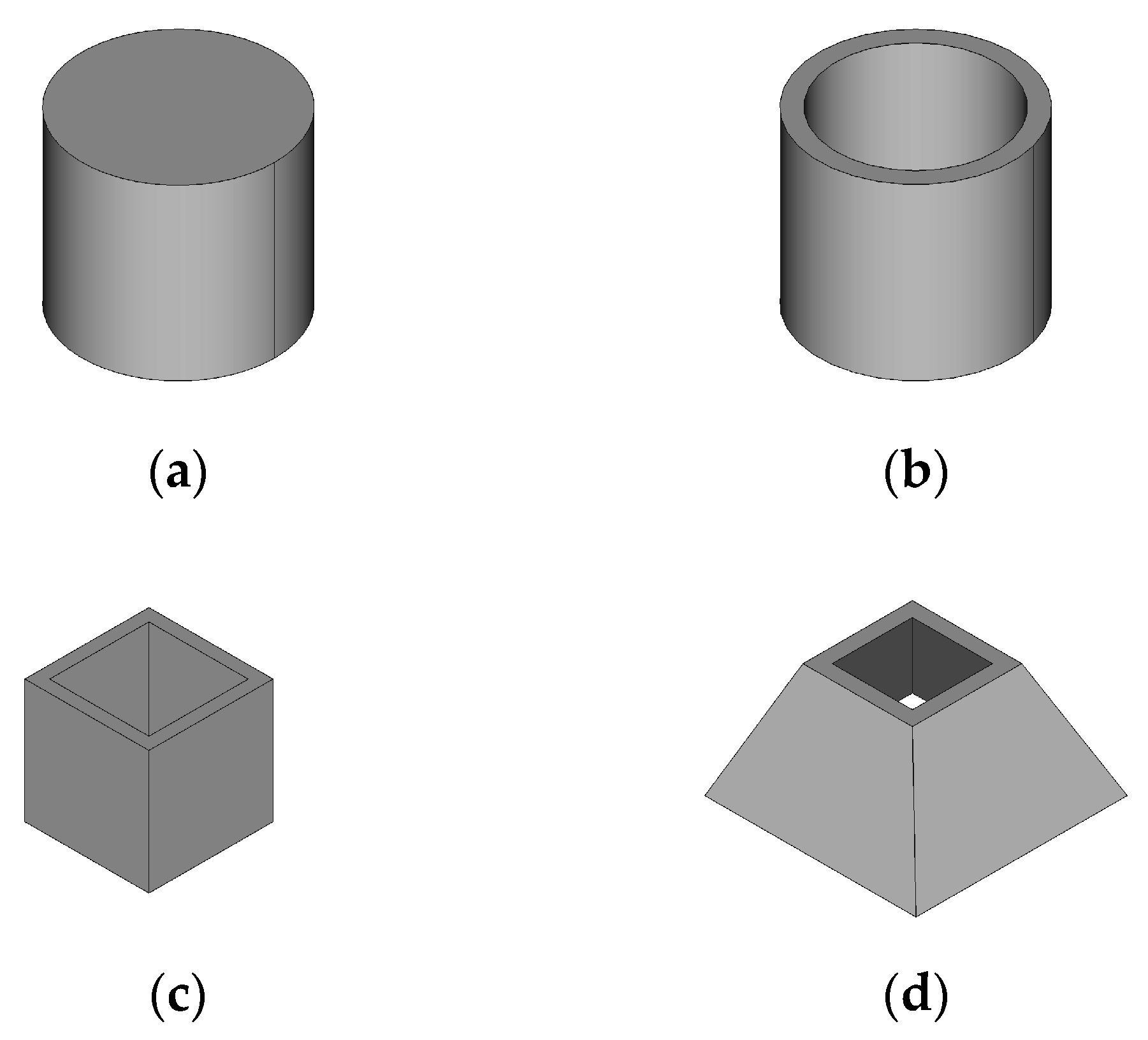
With the use of computer-aided design/computer-aided manufacturing (CAD/CAM) FreeCAD software, vibration dampers were designed. Damper geometries used in analysis are shown in Figure 6.
Each absorber volume was approximately 1000 mm3. This was an optimum value between a load that a single damper can withstand and printing time which needs to be as low as possible. Height of each damper was set to 10 mm.

2.3. Compression Test

The compression tests were carried out on a universal testing machine type AGS-X, Shimadzu, Japan. Traverse speed was set to 5 mm/min. Cyclic tensile test methodology can be found elsewhere in literature [68]. Cyclic compression test is conducted in the same way as tensile test, but sample is compressed instead. Sample was loaded with increasing force to the point where deformation reaches value 0.1, then unloaded to 0 N force. Next cycles were conducted cognately to increasing deformation: 0.2, 0.3, 0.4, 0.5 and 0.6. Hysteresis is taken as integral of load vs compression strain and expressed in units of J/mm3; see work [69].
After comparing the values of hysteresis and maximum compression in a given cycle, diagram was prepared. This was followed by curve fitting with polynomial of degree 3. Equation and R2 value were added into the chart.

2.4. Criterions

For each step of MDMP, one can adjust printing process parameters to meet desired criteria. In FDM technology, one can specify: lowest price criteria, lowest production time, lowest waste, highest quality, the best mechanical properties or performance criteria. Due to thesis of present work, authors decided to maximize damping in each MDMP step.

3. Results and Discussion

3.1. Selection of Material

Thermoplastic elastomers have a structure that varies depending on such factors as the soft-to-hard segment ratio and soft and hard segment molecular mass. It causes the structure and properties to change even though it is still the same polymer chemically [70] (pp. 3236–3237), [40] (pp. 161–164). For example, the copolymer soft segment length affects the mechanical properties of thermoplastic elastomer poly(trimethylene terephthalate)-block-poly(ethylene oxide) (PTT-b-PEO), with a soft segment length of 1130 g/mol and 3130 g/mol, and loss tangent values of 0.24 and 0.14, respectively [71].
Depending on the monomer type and synthesis method, it is possible to obtain various thermoplastic elastomers with different structures and physical and chemical properties [70] (pp. 3236–3237), [72] (pp. 10–20). Regarding the chemical structure of the macromolecule, the hardness and its other mechanical properties, including the damping characteristic of the polymer, vary. Table 2 shows examples of properties of main thermoplastic elastomer types commonly used in the industry. The most significant factors in the context of damping are tan δ, which is, as mentioned above, the qualitative damping indicator, modulus of elasticity, hardness and low glass transition temperature (Tg). The Tg of the polymer is the transition temperature below which the polymer behaves like a very stiff solid, and above which it behaves like a viscoelastic solid. Concerning the processing temperature, the FDM is similar to injection molding/extrusion techniques.
The hardness of general TPE groups is similar and is in the range of 30 ShA ÷ 75 ShD. During the design process of dampers, hardness needs to be selected for a specific application. When mechanical damage is likely to occur, the designer should choose a higher hardness material.
The modulus of elasticity is the stiffness of a material. Given a constant force acting on the printed part, the higher the modulus of elasticity, the less compliant the TPE material is to deformation. Therefore, it is more difficult to reach higher values of hysteresis (Figure 7b). It should be considered that the TPE’s modulus of elasticity is not a constant value in the whole range of deformations [40] (p. 166).
Phase separation due to the complete or limited miscibility of copolymer blocks is a very well-known behavior of plastics [70] (p. 3236). Two-phase polymer materials are of two types: blends of homopolymers (mechanical mixtures) [40] (pp. 181–182) and block copolymers [72] (pp. 51, 54). The morphology has a great impact on the overall properties of both groups of polymers mentioned above [40] (p. 182), [75,76]. As a result of the limited miscibility two-phase material, excellent mechanical and damping properties are obtained.
Block copolymers characterized by the size of the domains of 20 nm are compositions with the highest damping capacity, while approximately 100 nm give the material a higher impact resistance [72] (p. 165).
The compounding process leads to a polymer with new properties. In order to improve the mechanical properties and performance of the filament, various additives are used, e.g., antioxidants, nucleating agents, flame retardants, colorants, antistatic agents, slip agents, fillers and plasticizers. Of these, the most important are fillers: TiO2, carbon nanofibers, montmorillonite, graphite, graphene [77], chopped fiberglass, copper and bronze powder and carbon black [43]. In general, fillers that are popular in the last two decades, such as carbon black (CB), multiwall carbon nanotubes (MWCNT) or nano clay (NC), decrease damping and reduce shrinkage of TPEs, while additives such as hydrocarbon oils cause plasticizing of the compound (Table 3). Interestingly, the addition of graphite results in increased damping.
The compounding of the filament material components results in numerous new applications.

3.2. The Geometry of a Printed Part

The results of the compression test are presented in Figure 7a. The stress–strain curve shows that it is characteristic of soft TPE material. The plastic deformation is small when compared to the maximal strain in each cycle.
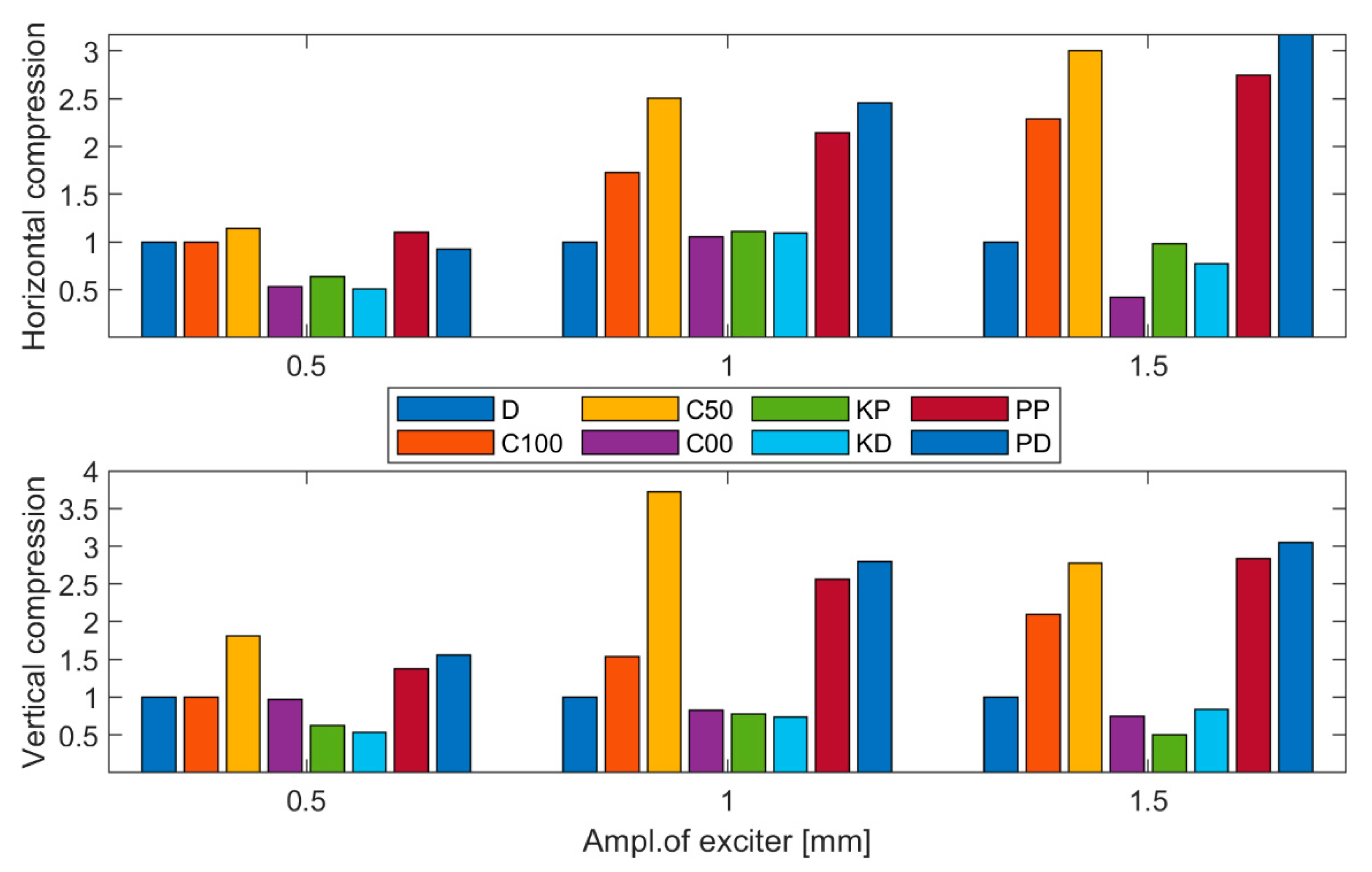
The damping data are shown on two bar diagrams (Figure 8). The upper diagram is the horizontal compression damping, which is the damping measured in the direction transversal of an iPad. The lower diagram is the vertical compression damping, which is the damping measured in the direction longitudinal of the iPad device (Figure 5).
Values of damping lower than 1.0 mean that damping occurs. The lower the value, the higher the damping.
The mechanical sieve shaker–dampers–iPad system turned out to be very unstable in excitation, with amplitudes higher than 1.5 mm. In this case, the dampers detached from the lower surface of the iPad. In amplitudes lower and equal to 1.5 mm, detachment did not occur.
Data gathered show that every damper failed to reduce the amplitude of vibration in the direction perpendicular to the iPad surface. Therefore, data referring to this direction were excluded from further analysis. This also indicated that the dominating deformation type was bending of the samples, rather than compression of the samples. This behavior is explained by the fact that the stiffness is higher in the direction parallel to the damper side wall.
The iPad device used in this study was not heavy enough to move the damper to an area of high damping. Figure 7b shows that the damping rises with the power of three, and thus heavier objects would induce a higher deformation and eventually a higher damping of the damper. Vibroisolators characterized by a higher infill density should be used with heavier loads. For telematics, whose mass is not too high, dampers with a relatively small volume and infill density are more effective.
Another step of the analysis of the vibration test data is to analyze the influence of the deviation of the side walls’ direction with respect to the vertical direction on damping. In this case, a general conclusion cannot be drawn, since the results of the damping are ambiguous. For example, in the horizontal direction, KP dampens more than KD in every case. While for the vertical direction, and in case of amplitudes 0.5 mm and 1 mm, KD dampens more. Similar behavior is seen for the pair of samples PP and PD, where PD in the horizontal direction dampens more if the excitation amplitudes are 1 mm and 1.5 mm. If 0.5 mm is used, then PD has worse damping. In case of vertical compression, PD has worse damping than PP in every vibration amplitude.
In general, the highest damping shown is by damper C00, KP and KD. The damping is slightly lower only for the horizontal and 1 mm excitation amplitude. Damper C00 turned out to be the most effective damper type from tested geometries.
In the horizontal direction, and at 1 mm amplitude, damping turns out to be lower for C00, KP and KD. To our surprise, the pyramid turned out to be inferior to the cylinder and cube geometry.

3.3. The Effect of Printing Parameters on Damper Properties

Printing parameters affecting mechanical properties and damping include deposition temperature, slicing and deposition strategy, single layer height and infill density [59].
Research in the additive manufacturing FDM field lacks works that explain how those parameters relate to the damping capacity of absorbers. Therefore, authors of the present publication could not discuss in detail the relationship between each printing parameter and damping. Some works explicitly show the relationship between energy absorption and damping, while others only concentrate on describing the pure mechanical properties of prints.
Thermoplastic elastomers have been used in FDM as well as in injection molding with success over many years [84]. The modulus of elasticity, loss tangent and hysteresis of the thermoplastic elastomer parts produced by injection molding and FDM are directly related to the process temperature. The higher the processing temperature, the higher the loss tangent, and the lower the modulus of elasticity and hysteresis of the soft block copolymer damper [84]. These are linked to structure. At lower processing temperatures, the polymer morphology is dominated by oriented cylinders. Injection molding and FDM have the same operating principle: a polymer in higher temperatures is melted and extruded through a nozzle and finally cooled down. Therefore, when increasing the printing temperature, a decrease in hysteresis is anticipated. The energy absorption is also dependent on the slicing and deposition strategy, e.g., a cylindrical-shaped polyamide print has the best energy absorption when printed in a circular manner and has the worst when printed horizontally [85]. The influence of layer thickness on the mechanical properties and damping for polyurethane thermoplastic elastomer is vague and beyond the scope of the present publication [86]. The results of our own research show that the lower the infill density, the better the damping of the small damper–iPad system (see Figure 8).
The most significant capability of FDM is printing parts of various infill types and degrees. The infill can range from 0% (print with only the outer wall) to 100% (the part without voids) [87]. The infill of a print is linear [42], lattice or honeycomb [34,88]. The latest research in the AM field shows that using FDM enabled obtaining even more complicated structures of infill, such as gyroid [30] or sea urchin-inspired supportless infill [81]. The impact of infill type on the damping of dampers made from thermoplastic elastomers is vague and not explained in literature as well.

3.4. Post-Printing Treatment

The main components of the possible post-printing treatment of a damper material are mechanical treatment, thermal treatment, chemical treatment and machining.
The mechanical properties of a polymer are temperature and strain-dependent, which is referred to as the temperature [89] and mechanical history of the polymer, including Mullins effect [19] (p. 585), [72] (p. 563), [71]. Generally, during thermal treatment, the polymer crystallinity increases, e.g., annealing [90] and mechanical deformation [81] (p. 49). Damper made of TPE material and compressed to a deformation of 50% is characterized by the increase in modulus of elasticity, dissipated energy and the plastic component of deformation (Figure 7a,b). When stiffer TPE is used, an increase in dissipated energy is anticipated [91].
In [92], it is reported that PLA tensile test samples after chemical treatment of the outer surface with dichloromethane vapors are distinguished by a higher tensile strength and lower elongation at break. TPE mechanical properties, as well as damping, should change after chemical treatment with specific solvent vapors. There is a lack of works that explain this phenomenon regarding TPE prints subjected to a compression test.
Chemical treatment is related to the chemical resistance of TPE. In general, the TPE’s resistance to various aggressive fluids depends on the chemical composition of the polymer. TPE-S is compliant with several solvents: cyclohexane, toluene, methyl ethyl ketone, diethyl ether and styrene. Mixtures of naphtha and toluene, hexane and toluene and hexane–toluene–ketone are known to be excellent solvents [40] (p. 170). Solvents of TPE-U divide into non-polar and polar. The former does not affect TPE-Us and include hexane and heptane. The latter are excellent solvents and include dimethylformamide, tetrahydrofuran, N-methyl pyrrolidone, dimethylacetamide and dimethyl sulfoxide [40] (p. 223). The TPE-E’s chemical compliance is composition and stiffness dependent. Ones with higher stiffness are more resistant to chemical solvents. However, TPE-Es are moderately resistant to acetone [40] (pp. 253–254). TPE-Vs, because of polypropylene (PP), which is a dominant part of this material, are very resistant to various solvents.
Reference [93] presents Computer Numerical Control (CNC) machining of print made from ABS polymer. Tests show that the quality of print surface after the machining operation increases. Besides, the quality of the print surface is cutting-depth dependent. Low hardness TPEs are difficult to machine materials. Machining can deteriorate the printed part surface. Therefore, the importance of soft TPE prints machining in ultimate treatment is marginal.
Reference [46] indicates that the print surface quality can be improved using a hot air jet. Increasing the air jet temperature and decreasing the air flow results in a decrease in surface roughness. The behavior that parts with a notch characterize by lower toughness and impact resistance is a well-known phenomenon. However, such behavior for the compression testing and damping of TPE samples is ambiguous. Therefore, along with CNC machining, it should be treated as insignificant.

4. Conclusions

Each level of MDMP enables the tailoring of the damping. At level I, a designer can choose one of many TPE groups. These have different physical properties, such as the modulus of elasticity, hardness and tan δ. FDM and TPE jointly create a pair one may use to solve technological or economic issues today; for example, avoiding fabricating very costly injection molds for small-scale production, or the possibility of tailoring the properties of prototypes to a specific use. At level II, geometry is also a significant factor. Using a similar TPE volume, but different geometry, hysteresis and damping may vary. The cylinder (C00) and hollow cube-type (KP, KD) absorber show the highest damping. Dampers, such as the pyramid (PP, PD) and cylinder (C100, C50), turned out to be characterized by the lowest damping. At level III, the optimal printing temperature value, layer height, infill density, slicing and deposition strategy and printing speed have to be selected. Each of the printing parameters influence the damping of a print in a different way. For example, if the printing temperature rises, the damping decreases, and if the infill density is low, the light telematics are dampened better. The layer height turned out to be difficult to characterize. A literature review shows that its influence on mechanical properties and damping is vague. At level IV, the post-processing operation is a final step of MDMP. The thermal and mechanical treatment affects the vibration absorber damping. The machining and air jet treatment are considered marginal for soft thermoplastic elastomers. The surface chemical treatment deserves little attention when compared to the thermal and mechanical treatment. It is worth noting that when the damper is deformed from 0 to 40% strain, damping increases from 0 to over 0.2 mJ/mm3 (Figure 7b).
An example of MDMP information flow may look as follows: a designer-selected TPE-S polymer used as a base material due to the fairly good hardness and highest tan δ. The geometry of the damper is the cylinder. Optimal printing parameters are the deposition temperature = recommended by filament manufacturer, layer height = 0.2 mm and infill density = 0%. The ultimate step is the mechanical compression post-printing treatment in order to increase hysteresis value.
As the authors of the present publication have shown, these absorbers made from thermoplastic elastomers have a high potential to become a new class of electric vehicles systems elements.
Future research opportunities and research directions. As a result of advanced research using FEM and modal analysis, the influence of geometry and material parameters on vibration damping can be optimized. The fabrication and analysis of simple geometry dampers is of key importance. After acquiring the knowledge of the simple geometry dampers’ mechanical behavior, one can design, print and analyze complex geometry dampers.
With regards to the damping–structure relationship of small-scale elastomer dampers, basic research still needs to be carried out. It is still unclear how basic parameters such as printing layer height, print orientation and internal structure, surface quality, chemical and mechanical finish affect vibration absorbers damping under consideration.
The effect identified during tests was the low mass of telematics that were used in this work (lower than 1 kg). In connection with a relatively good stiffness of small dampers, in order to obtain desired damping, vibroisolators should have an infill density close to 0% and a low cross-section area. However, the long-lasting use of dampers with such an area is vulnerable to fatigue cracking. Therefore, future research should involve the development of new solutions in damper macro geometry that allow for the use of composite materials. Moreover, one needs to take into consideration the use of two-nozzle two-component 3D printers in order to fabricate dampers with tough elastic outer walls and a soft core. Producing novel, soft and good damping filament material is also an option to consider.
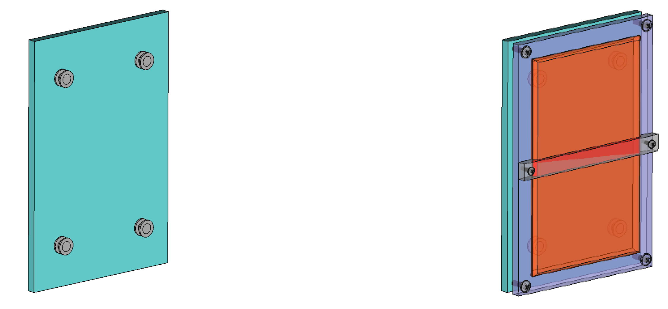
Figure 9 shows a vertically mounted telematic device (here, a smartphone was used as a telematic device model) that will withstand both an impact or vibrations coming from the source located in back of the plate.

Author Contributions

Conceptualization, J.W. and J.C.; data curation, J.W. and J.C.; formal analysis, J.W. and J.C.; investigation, J.W. and J.C.; methodology, J.W. and J.C.; project administration, J.W. and J.C.; resources, J.W. and J.C.; supervision, J.W. and J.C.; validation, J.W. and J.C.; visualization, J.W. and J.C.; writing—original draft, J.W. and J.C.; writing—review and editing, J.W. and J.C. All authors have read and agreed to the published version of the manuscript.

Funding

This research was funded by Maritime University of Szczecin, grant number 1/S/KPT/2021 “Life cycle management of means of transport and infrastructure facilities”.

Institutional Review Board Statement

Not applicable.

Informed Consent Statement

Not applicable.

Data Availability Statements

The data presented in this study are available on request from the corresponding author. The data are not publicly available due to novel character of research.

Acknowledgments

We thank Lech Dorobczyński (Maritime University of Szczecin, Mechatronics and Electrical Engineering Faculty) for verifying the numerical models used in the article.

Conflicts of Interest

The authors declare no conflict of interest.

References

  1. Watrobski, J.; Malecki, K.; Kijewska, K.; Iwan, S.; Karczmarczyk, A.; Thompson, R.G. Multi-Criteria Analysis of Electric Vans for City Logistics. Sustainability 2017, 9, 1453. [Google Scholar] [CrossRef] [Green Version]
  2. Iwan, S.; Kijewska, K.; Kijewski, D. Possibilities of Applying Electrically Powered Vehicles in Urban Freight Transport. In Procedia Social and Behavioral Sciences, Proceedings of the 1st International Conference on Green Cities—Green Logistics for Greener Cities, Szczecin, Poland, 19–21 May 2014; Iwan, S., Thompson, R.G., Eds.; Elsevier: Amsterdam, The Netherlands, 2014; pp. 87–101. [Google Scholar] [CrossRef] [Green Version]
  3. Kijewska, K.; Iwan, S.; Małecki, K. Applying Multi-Criteria Analysis of Electrically Powered Vehicles Implementation in Urban Freight Transport. In Procedia Computer Science, Proceedings of the 23rd KES International Conference on Knowledge-Based and Intelligent Information and Engineering Systems (KES), Budapest, Hungary, 4–6 September 2019; Rudas, I.J., Janos, C., Toro, C., Botzheim, J., Howlett, R.J., Jain, L.C., Eds.; Elsevier: Amsterdam, The Netherlands, 2019; pp. 1558–1567. [Google Scholar] [CrossRef]
  4. Iwan, S.; Allesch, J.; Celebi, D.; Kijewska, K.; Hoe, M.; Klauenberg, J.; Zajicek, J. Electric mobility in European urban freight and logistics—Status and attempts of improvement. In Transportation Research Procedia, Proceedings of the 3rd International Conference on Green Cities—Green Logistics for Greener Cities, Szczecin, Poland, 13–14 September 2018; Iwan, S., Thompson, R.G., Kijewska, K., Eds.; Elsevier: Amsterdam, The Netherlands, 2018; pp. 112–123. [Google Scholar] [CrossRef]
  5. Grzesica, D. Measurement and analysis of truck vibrations during off-road transportation. In MATEC Web of Conferences, Proceedings of the 14th International Conference on Vibration Engineering and Technology of Machinery (VETOMAC), Lisbon, Portugal, 10–13 September 2018; Maia, N., Dimitrovova, Z., Eds.; E D P Sciences: Les Ulis, France, 2018. [Google Scholar] [CrossRef]
  6. Agostinacchio, M.; Ciampa, D.; Olita, S. The vibrations induced by surface irregularities in road pavements—A Matlab (R) approach. Eur. Transp. Res. Rev. 2014, 6, 267–275. [Google Scholar] [CrossRef] [Green Version]
  7. Reina, G.; Leanza, A.; Messina, A. On the vibration analysis of off-road vehicles: Influence of terrain deformation and irregularity. J. Vib. Control. 2018, 24, 5418–5436. [Google Scholar] [CrossRef]
  8. Amy, R.A.; Aglietti, G.S.; Richardson, G. Reliability analysis of electronic equipment subjected to shock and vibration—A review. Shock Vib. 2009, 16, 45–59. [Google Scholar] [CrossRef]
  9. Al-Yafawi, A.; Yu, D.; Park, S.; Pitarresi, J.; Chung, S. Reliability assessment of electronic components under random vibration loading. In Proceedings of the 59th Electronic Components and Technology Conference, San Diego, CA, USA, 26–29 May 2009; IEEE: New York, NY, USA, 2009; Volume 1–4. [Google Scholar] [CrossRef]
  10. Ham, S.J.; Lee, S.B. Experimental study for reliability of electronic packaging under vibration. Exp. Mech. 1996, 36, 339–344. [Google Scholar] [CrossRef]
  11. U.S. Department of Defence. Test Method Standard 750D; Semiconductor Devices: Washington, DC, USA, 1995. [Google Scholar]
  12. U.S. Department of Defence. Test Method Standard 883E; Microcircuits: Washington, DC, USA, 1996. [Google Scholar]
  13. Kiciński, J. Dynamika wirników i łożysk ślizgowych. In Maszyny Przepływowe; Burka, E.S., Ed.; Wydawnictwo IMP PAN: Gdańsk, Poland, 2005; p. 28. [Google Scholar]
  14. Solecki, L. Assessment of annual exposure of private farmers to the whole-body mechanical vibration on selected family farms of animal production profile. Med. Pr. 2010, 61, 143–154. [Google Scholar]
  15. Kubo, M.; Terauchi, F.; Aoki, H.; Matsuoka, Y. An investigation into a synthetic vibration model for humans: An investigation into a mechanical vibration human model constructed according to the relations between the physical, psychological and physiological reactions of humans exposed to vibration. Int. J. Ind. Ergon. 2001, 27, 219–232. [Google Scholar] [CrossRef]
  16. Iwan, S.; Małecki, K.; Korczak, J. Impact of Telematics on Efficiency of Urban Freight Transport. In Activities of Transport Telematics, Proceedings of the 13th International Conference on Transport Systems Telematics (TST), Katowice, Poland, 23–26 October 2013; Mikulski, J., Ed.; Springer: New York, NY, USA, 2013. [Google Scholar]
  17. Symans, M.D.; Constantinou, M.C. Semi-active control systems for seismic protection of structures: A state-of-the-art review. Eng. Struct. 1999, 21, 469–487. [Google Scholar] [CrossRef]
  18. Soong, T.T.; Spencer, B.F. Supplemental energy dissipation: State-of-the-art and state-of-the practice. Eng. Struct. 2002, 24, 243–259. [Google Scholar] [CrossRef]
  19. Van Krevelen, D.W.; Te Nijenhuis, K. Properties of Polymers, 4th ed.; Elsevier: Amsterdam, The Netherlands, 2009. [Google Scholar]
  20. Adams, R. Vibration Damping of Adhesively Bonded Joints. In Handbook of Adhesion Technology; Da Silva, L.F.M., Ochsner, A., Adams, R.D., Eds.; Springer: Berlin, Germany, 2011. [Google Scholar] [CrossRef]
  21. Soedel, W.; Qatu, M.S. Vibrations of Shells and Plates, 3rd ed.; Marcel Dekker, Inc.: New York, NY, USA, 2005. [Google Scholar]
  22. Shen, M.Y.; Chiou, Y.C.; Tan, C.M.; Wu, C.C.; Chen, W.J. Effect of Wall Thickness on Stress-Strain Response and Buckling Behavior of Hollow-Cylinder Rubber Fenders. Materials 2020, 13, 1170. [Google Scholar] [CrossRef] [Green Version]
  23. Benyoucef, A.; Leblouba, M.; Zerzour, A. Stiffness and energy dissipation of Oval Leaf Spring mounts under unidirectional line loading. Mech. Ind. 2017, 18, 4. [Google Scholar] [CrossRef]
  24. Vithani, K.; Goyanes, A.; Jannin, V.; Basit, A.; Gaisford, S.; Boyd, B. An Overview of 3D Printing Technologies for Soft Materials and Potential Opportunities for Lipid-based Drug Delivery Systems. Pharm. Res. 2019, 36, 1–20. [Google Scholar] [CrossRef] [Green Version]
  25. Dizon, J.R.C.; Espera, A.H.; Chen, Q.Y.; Advincula, R.C. Mechanical characterization of 3D-printed polymers. Addit. Manuf. 2018, 20, 44–67. [Google Scholar] [CrossRef]
  26. Stansbury, J.W.; Idacavage, M. 3D printing with polymers: Challenges among expanding options and opportunities. Dent. Mater. 2016, 32, 54–64. [Google Scholar] [CrossRef] [PubMed]
  27. Wohlers, T.; Gornet, T. History of Additive Manufacturing. Wohler Associates. Available online: http://www.wohlersassociates.com/history2014.pdf (accessed on 27 February 2021).
  28. Ligon, S.; Liska, R.; Stampfl, J.; Gurr, M.; Mulhaupt, R. Polymers for 3D printing and customized additive manufacturing. Chem. Rev. 2017, 117, 10212–10290. [Google Scholar] [CrossRef] [Green Version]
  29. Kumar, N.; Jain, P.; Tandon, P.; Pandey, P. The effect of process parameters on tensile behavior of 3D printed flexible parts of ethylene vinyl acetate (EVA). J. Manuf. Process. 2018, 35, 317–326. [Google Scholar] [CrossRef]
  30. Maconachie, T.; Tino, R.; Lozanovski, B.; Watson, M.; Jones, A.; Pandelidi, C.; Alghamdi, A.; Almalki, A.; Downing, D.; Brandt, M.; et al. The compressive behaviour of ABS gyroid lattice structures manufactured by fused deposition modelling. Int. J. Adv. Manuf. Technol. 2020, 107, 4449–4467. [Google Scholar] [CrossRef]
  31. Rajzer, I.; Kurowska, A.; Jabłoński, A.; Jatteau, S.; Śliwka, M.; Ziąbka, M.; Menaszek, E. Layered gelatin/PLLA scaffolds fabricated by electrospinning and 3D printing for nasal cartilages and subchondral bone reconstruction. Mater. Des. 2018, 155, 297–306. [Google Scholar] [CrossRef]
  32. Bose, S.; Vahabzadeh, S.; Bandyopadhyay, A. Bone tissue engineering using 3D printing. Mater. Today 2018, 16, 496–504. [Google Scholar] [CrossRef]
  33. Jia, Y.; He, H.; Peng, X.; Meng, S.; Chen, J.; Geng, Y. Preparation of a new filament based on polyamide-6 for three-dimensional printing. Polym. Eng. Sci. 2017, 57, 1322–1328. [Google Scholar] [CrossRef]
  34. Pollard, D.; Ward, C.; Herrmann, G.; Etches, J. The manufacture of honeycomb cores using Fused Deposition Modeling. Adv. Manuf. Polym. Compos. Sci. 2017, 3, 21–31. [Google Scholar] [CrossRef] [Green Version]
  35. Liao, G.X.; Li, Z.X.; Cheng, Y.C.; Xu, D.D.; Zhu, D.C.; Jiang, S.L.; Guo, J.J.; Chen, X.D.; Xu, G.J.; Zhu, Y.J. Properties of oriented carbon fiber/polyamide 12 composite parts fabricated by fused deposition modeling. Mater. Des. 2018, 139, 283–292. [Google Scholar] [CrossRef]
  36. Morales, N.G.; Fleck, T.J.; Rhoads, J.F. The effect of interlayer cooling on the mechanical properties of components printed via fused deposition. Addit. Manuf. 2018, 24, 243–248. [Google Scholar] [CrossRef]
  37. Saari, M.; Galla, M.; Cox, B.; Krueger, P.; Cohen, A.; Richer, E. Additive Manufacturing of Soft and Composite Parts from Thermoplastic Elastomers. In Proceedings of the Solid Freeform Fabrication Symposium, Austin, TX, USA, 18 January 2015; pp. 949–958. [Google Scholar]
  38. Kumar, N.; Jain, P.; Tandon, P.; Pandey, P. Additive manufacturing of flexible electrically conductive polymer composites via CNC-assisted fused layer modeling process. J. Braz. Soc. Mech. Sci. 2018, 40, 1–13. [Google Scholar] [CrossRef]
  39. Achillas, C.; Aidonis, D.; Iakovou, E.; Thymianidis, M.; Tzetis, D. A methodological framework for the inclusion of modern additive manufacturing into the production portfolio of a focused factory. J. Manuf. Syst. 2015, 37, 328–339. [Google Scholar] [CrossRef]
  40. Drobny, J.G. Handbook of Thermoplastic Elastomers, 1st ed.; William Andrew Publishing: Norwich, NY, USA, 2007. [Google Scholar]
  41. Tofail, S.A.M.; Koumoulos, E.P.; Bandyopadhyay, A.; Bose, S.; O’Donoghue, L.; Charitidis, C. Additive manufacturing: Scientific and technological challenges, market uptake and opportunities. Mater. Today 2018, 21, 22–37. [Google Scholar] [CrossRef]
  42. Abbott, A.C.; Tandon, G.P.; Bradford, L.P.; Koerner, H.; Baur, J.W. Process-structure-property effects on ABS bond strength in fused filament fabrication. Addit. Manuf. 2018, 19, 29–38. [Google Scholar] [CrossRef]
  43. Przybytek, A.; Kucińska-Lipka, J.; Janik, H. Thermoplastic elastomer filaments and their application in 3D printing. Elastomery 2016, 20, 32–39. [Google Scholar]
  44. Domingo-Espin, M.; Puigoriol-Forcada, J.M.; Garcia-Granada, A.A.; Lluma, J.; Borros, S.; Reyes, G. Mechanical property characterization and simulation of fused deposition modeling polycarbonate parts. Mater. Des. 2015, 83, 670–677. [Google Scholar] [CrossRef]
  45. Zander, N.E.; Gillan, M.; Burckhard, Z.; Gardea, F. Recycled polypropylene blends as novel 3D printing materials. Addit. Manuf. 2019, 25, 122–130. [Google Scholar] [CrossRef]
  46. Adel, M.; Abdelaal, O.; Gad, A.; Nasr, A.B.; Khalil, A. Polishing of fused deposition modeling products by hot air jet: Evaluation of surface roughness. J. Mater. Process. Technol. 2018, 251, 73–82. [Google Scholar] [CrossRef]
  47. Hamidi, A.; Tadesse, Y. Single step 3D printing of bioinspired structures via metal reinforced thermoplastic and highly stretchable elastomer. Compos. Struct. 2019, 210, 250–261. [Google Scholar] [CrossRef]
  48. Kumar, N.; Jain, P.K.; Tandon, P.; Pandey, P.M. Extrusion-based additive manufacturing process for producing flexible parts. J. Braz. Soc. Mech. Sci. Eng. 2018, 40, 1–12. [Google Scholar] [CrossRef]
  49. Lathers, S.; Mousa, M.; La Belle, J. Additive manufacturing Fused Filament Fabrication three-dimensional printed pressure sensor for prosthetics with low elastic modulus and high filler ratio filament composites. 3D Print. Addit. Manuf. 2017, 4, 30–40. [Google Scholar] [CrossRef]
  50. Korger, M.; Bergschneider, J.; Lutz, M.; Mahltig, B.; Finsterbush, K.; Rabe, M. Possible Applications of 3D Printing Technology on Textile Substrates. In Proceedings of the 48th Conference of the International Federation of Knitting Technologists (IFKT), Moenchengladbach, Germany, 8–11 June 2016; Aumann, S., Ehrmann, A., Weber, M.O., Eds.; IOP Publishing Ltd.: Bristol, UK, 2016. [Google Scholar] [CrossRef] [Green Version]
  51. Kannan, S.; Ramamoorthy, M. Mechanical characterization and experimental modal analysis of 3D Printed ABS, PC and PC-ABS materials. Mater. Res. Express 2020, 7, 1–11. [Google Scholar] [CrossRef]
  52. Jiang, S.L.; Liao, G.X.; Xu, D.D.; Liu, F.H.; Li, W.; Cheng, Y.C.; Li, Z.X.; Xu, G.J. Mechanical properties analysis of polyetherimide parts fabricated by fused deposition modeling. High. Perform. Polym. 2018, 31, 97–106. [Google Scholar] [CrossRef]
  53. Fu, W.H.; Chung, D.D.L. Vibration reduction ability of polymers, particularly polymethylmethacrylate and polytetrafluoroethylene. Polym. Polym. Compos. 2001, 9, 423–426. [Google Scholar] [CrossRef]
  54. Hudnut, S.W.; Chung, D.D.L. Use of submicron diameter carbon filaments for reinforcement between continuous carbon fiber layers in a polymer-matrix composite. Carbon 1995, 33, 1627–1631. [Google Scholar] [CrossRef]
  55. Luo, X.C.; Chung, D.D.L. Vibration damping using flexible graphite. Carbon 2000, 38, 1499–1524. [Google Scholar] [CrossRef]
  56. Elkins, K.; Nordby, H.; Janak, C.; Gray, R.W.; Bohn, J.H.; Baird, D.G. Soft elastomers for fused deposition modelling. In Solid Freeform Fabrication Proceedings (Series), Proceedings of the 8th Solid Freeform Fabrication (SFF) Symposium, Austin, TX, USA, 11–13 August 1997; Bourell, D.L., Beaman, J.J., Crawford, R.H., Marcus, H.L., Barlow, J.W., Eds.; Univ. Texas Austin: Austin, TX, USA, 1997; pp. 441–448. [Google Scholar]
  57. Christ, J.F.; Aliheidari, N.; Potschke, P.; Ameli, A. Bidirectional and Stretchable Piezoresistive Sensors Enabled by Multimaterial 3D Printing of Carbon Nanotube/Thermoplastic Polyurethane Nanocomposites. Polymers 2019, 11, 11. [Google Scholar] [CrossRef] [Green Version]
  58. Noorani, R. Materials for 3D printing. In 3D Printing: Technology, Applications, and Selection; CRC Press: Boca Raton, FL, USA, 2018. [Google Scholar]
  59. Bahr, F.; Westkamper, E. Correlations between influencing parameters and quality properties of components produced by Fused Deposition Modeling. In Procedia CIRP, Proceedings of the 51st CIRP Conference on Manufacturing Systems (CIRP CMS), Stockholm, Sweden, 16–18 May 2018; Wang, L., Ed.; Elsevier: Amsterdam, The Netherlands, 2018; pp. 1214–1219. [Google Scholar] [CrossRef]
  60. Konatowski, S.; Golgowski, M. Road surface hazard warning system for vehicle drivers. In Proceedings of the 2018 14th International Conference on Advanced Trends in Radioelectronics, Telecommunications and Computer Engineering (TCSET), Lviv, Ukraine, 20–24 February 2018; IEEE: New York, NY, USA, 2018; pp. 421–425. [Google Scholar]
  61. Bittel, A.; Elazzazi, A.; Bittel, D. Accuracy and Precision of an Accelerometer-Based Smartphone App Designed to Monitor and Record Angular Movement over Time. Telemed. E-Health 2016, 22, 302–309. [Google Scholar] [CrossRef] [Green Version]
  62. Mobark, M.; Chuprat, S.; Mantoro, T. Improving the accuracy of complex activities recognition using accelerometer-embedded mobile phone classifiers. In Proceedings of the 2017 Second International Conference on Informatics and Computing (ICIC), Jayapura, Indonesia, 1–3 November 2017; pp. 1–5. [Google Scholar] [CrossRef]
  63. Alberts, J.; Hirsch, J.; Koop, M.; Schindler, D.; Kana, D.; Linder, S.; Campbell, S.; Thota, A. Using Accelerometer and Gyroscopic Measures to Quantify Postural Stability. J. Athl. Train. 2015, 50, 578–588. [Google Scholar] [CrossRef] [PubMed] [Green Version]
  64. Allmendinger, R.; Siron, C.; Scott, C. Structural data collection with mobile devices: Accuracy, redundancy, and best practices. J. Struct. Geol. 2017, 102, 98–112. [Google Scholar] [CrossRef]
  65. Ibrahim, A.; Eltawil, A.; Na, Y.; El-Tawil, S. Accuracy Limits of Embedded Smart Device Accelerometer Sensors. IEEE Trans. Instrum. Meas. 2020, 69, 5488–5496. [Google Scholar] [CrossRef]
  66. Google Play Store. BOSCH iNVH. Available online: https://play.google.com/store/apps/details?id=com.bosch.nvh_analysis&hl=pl&gl=US (accessed on 5 June 2021).
  67. Phyphox Sensor Database. Available online: https://phyphox.org/sensordb/ (accessed on 5 June 2021).
  68. Szymczyk, A.; Nastalczyk, J.; Sablong, R.J.; Roslaniec, Z. The influence of soft segment length on structure and properties of poly(trimethylene terephthalate)-block-poly(tetrametylene oxide) segmented random copolymers. In Proceedings of the 10th International Conference on Polymers for Advanced Technologies (PAT 2009), Jerusalem, Israel, 11–14 October 2009; Wiley: Hoboken, NJ, USA, 2009; pp. 72–83. [Google Scholar] [CrossRef]
  69. Gorce, J.N.; Hellgeth, J.W.; Ward, T.C. Mechanical hysteresis of a polyether polyurethane thermoplastic elastomer. Polym. Eng. Sci. 1993, 33, 1170–1176. [Google Scholar] [CrossRef]
  70. Adams, D.J.; Topham, P.D. Assembly of Block Copolymers. In Supramolecular Chemistry: From Molecules to Nanomaterials; Steed, J.W., Gale, P.A., Eds.; John Wiley & Sons, Ltd.: Hoboken, NJ, USA, 2012; Volume 7, pp. 3235–3253. [Google Scholar]
  71. Piesowicz, E.; Paszkiewicz, S.; Szymczyk, A. Phase Separation and Elastic Properties of Poly(Trimethylene Terephthalate)-block-poly(Ethylene Oxide) Copolymers. Polymers 2016, 8, 237. [Google Scholar] [CrossRef] [Green Version]
  72. Sperling, L.H. Introduction to Physical Polymer Science, 4th ed.; John Wiley & Sons, Inc.: Hoboken, NJ, USA, 2006. [Google Scholar]
  73. Helal, E.; Demarquette, N.R.; Amurin, L.G.; David, E.; Carastan, D.J.; Frechette, M. Styrenic block copolymer-based nanocomposites: Implications of nanostructuration and nanofiller tailored dispersion on the dielectric properties. Polymer 2015, 64, 139–152. [Google Scholar] [CrossRef]
  74. Naskar, K.; Gohs, U.; Wagenknecht, U.; Heinrich, G. PP-EPDM thermoplastic vulcanisates (TPVs) by electron induced reactive processing. Express Polym. Lett. 2009, 3, 677–683. [Google Scholar] [CrossRef]
  75. Puskas, J.E.; Antony, P.; El Fray, M.; Altstadt, V. The effect of hard and soft segment composition and molecular architecture on the morphology and mechanical properties of polystyrene-polyisobutylene thermoplastic elastomeric block copolymers. Eur. Polym. J. 2003, 39, 2041–2049. [Google Scholar] [CrossRef]
  76. Puskas, J.E.; Dos Santos, L.M.; Fischer, F.; Gotz, C.; El Fray, M.; Altstadt, V.; Tomkins, M. Fatigue testing of implantable specimens: Effect of sample size and branching on the dynamic fatigue properties of polyisobutylene-based biomaterials. Polymer 2009, 50, 591–597. [Google Scholar] [CrossRef]
  77. Wang, X.; Jiang, M.; Zhou, Z.W.; Gou, J.H.; Hui, D. 3D printing of polymer matrix composites: A review and prospective. Compos. Part B 2017, 110, 442–458. [Google Scholar] [CrossRef]
  78. Inukai, S.; Noguchi, T.; Niihara, K.; Oyaizu, N.; Yamada, E.; Inagaki, S.; Takeuchi, K.; Endo, M. Properties and Interfacial Structure Analysis of MWCNT/ESBS Composites. Ind. Eng. Chem. Res. 2015, 54, 8690–8698. [Google Scholar] [CrossRef]
  79. Praveen, S.; Bahadur, J.; Yadav, R.; Billa, S.; Patro, T.U.; Rath, S.K.; Ratna, D.; Patri, M. Tunable viscoelastic and vibration damping properties of a segmented polyurethane synergistically reinforced with carbon black and anisotropic additives. Appl. Acoust. 2020, 170, 1–12. [Google Scholar] [CrossRef]
  80. Zheng, N.; Wang, Q.Z.; Cui, C.X.; Yin, F.X.; Jiao, Z.X.; Li, H.Z. Fabrication and damping behaviors of novel polyurethane/TiNiCu composites. Phys. B-Condens. Matter 2020, 582, 1–8. [Google Scholar] [CrossRef]
  81. Bhowmick, A.K.; Stephens, H.L. Handbook of Elastomers, 2nd ed.; Marcel Dekker, Inc.: New York, NY, USA, 2001. [Google Scholar]
  82. Broza, G.; Schulte, K. Melt processing and filler/matrix interphase in carbon nanotube reinforced poly(ether-ester) thermoplastic elastomer. In Polymer Engineering and Science, Proceedings of the 15th Annual Polychar World Forum on Advanced Materials, Buzios, Brazil, 16–20 April 2007; Wiley-Blackwell: Hoboken, NJ, USA, 2007; pp. 2033–2038. [Google Scholar] [CrossRef]
  83. Le, H.H.; Heidenreich, D.; Kolesov, I.S.; Ilisch, S.; Radusch, H.J. Effect of Carbon Black Addition and Its Phase Selective Distribution on the Stress Relaxation Behavior of Filled Thermoplastic Vulcanizates. J. Appl. Polym. Sci. 2010, 117, 2622–2634. [Google Scholar] [CrossRef]
  84. Zhao, Y.S.; Ning, N.Y.; Hu, X.; Li, Y.H.; Chen, F.; Fu, Q. Processing temperature dependent mechanical response of a thermoplastic elastomer with low hard segment. Polymer 2012, 53, 4310–4317. [Google Scholar] [CrossRef]
  85. Wang, J.; Xiang, J.Y.; Lin, H.; Wang, K.; Yao, S.; Peng, Y.; Rao, Y.N. Effects of Scanning Strategy and Printing Temperature on the Compressive Behaviors of 3D Printed Polyamide-Based Composites. Polymers 2020, 12, 1783. [Google Scholar] [CrossRef] [PubMed]
  86. Chaudhry, M.S.; Czekanski, A. Evaluating FDM Process Parameter Sensitive Mechanical Performance of Elastomers at Various Strain Rates of Loading. Materials 2020, 13, 3202. [Google Scholar] [CrossRef]
  87. Alvarez, K.L.; Lagos, R.F.; Aizpun, M. Investigating the influence of infill percentage on the mechanical properties of fused deposition modelled ABS parts. Ing. E Investig. 2016, 36, 110–116. [Google Scholar] [CrossRef] [Green Version]
  88. Kumar, A.; Verma, S.; Jeng, J.Y. Supportless Lattice Structures for Energy Absorption Fabricated by Fused Deposition Modeing. 3D Print. Addit. Manuf. 2020, 7, 85–96. [Google Scholar] [CrossRef]
  89. Amin, A.F.M.S.; Lion, A.; Hofer, P. Effect of temperature history on the mechanical behaviour of a filler-reinforced NR/BR blend: Literature review and critical experiments. Z. Angew. Math. Mech. 2010, 90, 347–369. [Google Scholar] [CrossRef]
  90. Ren, Y.M.; Zou, H.; Wang, S.J.; Liu, J.Y.; Gao, D.L.; Wu, C.J.; Zhang, S.J. Effect of annealing on microstructure and tensile properties of polypropylene cast film. Colloid. Polym. Sci. 2018, 296, 41–51. [Google Scholar] [CrossRef]
  91. El Fray, M.; Altstadt, V. Fatigue behaviour of multiblock thermoplastic elastomers. 3. Stepwise increasing strain test of poly (aliphatic/aromatic-ester) copolymers. Polymer 2004, 45, 263–273. [Google Scholar] [CrossRef]
  92. Jin, Y.F.; Wan, Y.; Zhang, B.; Liu, Z.Q. Modeling of the chemical finishing process for polylactic acid parts in fused deposition modeling and investigation of its tensile properties. J. Mater. Process. Technol. 2017, 240, 233–239. [Google Scholar] [CrossRef]
  93. Boschetto, A.; Bottini, L.; Veniali, F. Finishing of Fused Deposition Modeling parts by CNC machining. Rob. Comput. Integr. Manuf. 2016, 41, 92–101. [Google Scholar] [CrossRef]
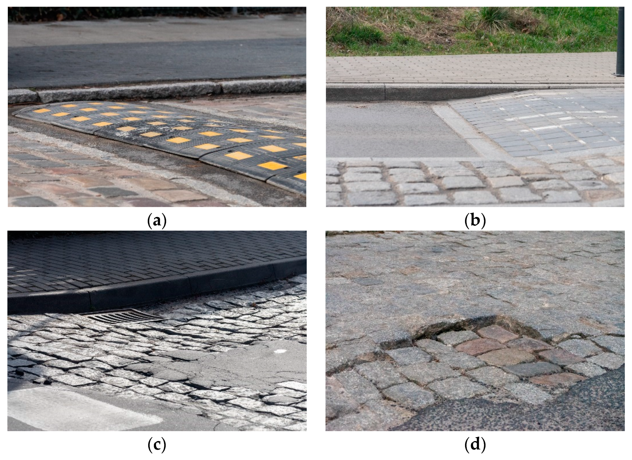
Figure 1. Main types of traffic slow-down devices (a,b) and examples of roadway failures (c,d).
Energies 14 04193 g001
Figure 2. Changes in acceleration components during the home delivery stage. Registration: Matlab Mobile for Android on Huawei Mediapad M3, sampling rate 100 Hz, accelerometers work in ±30 m/s2 (3 g) acceleration range, 8 bit resolution. Samples below 4000, exit from the national road; 4000 to 6000, side road with cobbled surface; over 6000, driving on a cobbled street with slowing down thresholds type “sleeping policeman”. Driving speed below 30 km/h, distance of the trip: 250 m.
Energies 14 04193 g002
Figure 3. Multilevel design and manufacturing process (MDMP).
Energies 14 04193 g003
Figure 4. Multilevel design and manufacturing process components.
Energies 14 04193 g004
Figure 5. Damping vibration test setup: left hand side, directions of acceleration measurement; right hand side, set of four dampers placed on the top of mechanical sieve shaker.
Energies 14 04193 g005
Figure 6. Dampers prototypes (own research; distinct geometry): (a) cylinder C100 and C50; (b) cylinder C00; (c) cube KP and KD; (d) pyramid PP, PD.
Energies 14 04193 g006
Figure 7. Mechanical properties of soft (75 Shore A hardness) TPE print: (a) stress vs. strain in compression test, (b) hysteresis vs. strain curve.
Energies 14 04193 g007
Figure 8. Results of vibration test; the lower the value, the better the damping.
Energies 14 04193 g008
Figure 9. Practical use of small-scale dampers: left hand side, plate with small-scale damper prototypes attached; right hand side, vibration setup ready for testing.
Energies 14 04193 g009
Table 1. Geometry and symbols of printed dampers.
Model SymbolModel GeometryInfill Density, %Remarks
C100Cylinder100Infill type—linear
C50Cylinder50Infill type—linear
C00Cylinder00Printed model walls only.
KPCube00Printed model walls only.
Direction parallel to side walls.
KDCube00Printed model walls only.
Direction deviated by 45 degrees from side walls (diamond)
PPPyramid00Printed model walls only.
Direction parallel to side walls.
PDPyramid00Printed model walls only.
Direction deviated by 45 degrees from side walls (diamond)
Table 2. Basic thermoplastic elastomers and their physical properties according to [40] (pp. 161–164, 170, 174, 215–220, 254, 329), [68,73,74].
Material PropertyTPE-STPE-UTPE-ETPE-V
Density, g/ccm0.9 ÷ 1.11.1 ÷ 1.31.1 ÷ 1.30.94 ÷ 1.0
Tg, °C−60 ÷ −90−46 ÷ −100−40−60
Modulus of elasticity, MPa1 ÷ 11 a60 b15 ÷ 7105 ÷ 8
Hardness30 ShA ÷ 75 ShD60 ShA ÷ 70 ShD60 ShA ÷ 70 ShD55 ShA ÷ 50 ShD
Tensile strength, MPaLowLow to highLow to highFair
Ultimate elongation, %250 ÷ 1100530 b600 b530 b
tan δ in maximum, -0.80.2 ÷ 0.30.25 ÷ 0.50.35 ÷ 0.4
Processing temperature, °C140 ÷ 185 c170 ÷ 190 d180 ÷ 260 e204 ÷ 232 f
a modulus for 300% strain, b parameter strongly dependent on TPE chemical structure, c as per Elastron D100® polymer, d as per Apilon 52® polymer, e as per Hytrel® polymer, f as per Santoprene™ 101 87 polymer.
Table 3. Main types of thermoplastic elastomers and influence of fillers on mechanical properties, damping capacity and processability; PA-NBR compound of polyamide (PA) and butadiene-acrylonitrile rubber.
TPE TypeDampingProcessability Issues
TPE-SAddition of CB or MWCNT decreases damping (tan δ) [78]
NC decreases damping (tan δ) [73]
Improved by adding polystyrene (PS) or oils
[40] (p. 169).
Shrinkage (0.5–2%) can occur, but can be lowered by addition of a filler
TPE-U, PUAddition of graphite, aramid fiber or NC decreases damping (tan δ) [79]
Addition of TiNiCu + MWCNT decreases damping, but graphite increases damping [80]
To facilitate processability by injection, molding release agents are used [81] (p. 406)
TPE-EAddition of MWCNT causes decrease in damping (tan δ) [82]Shrinkage (0.5–3%) can occur. The higher the hardness, the higher shrinkage [40] (pp. 258–259)
TPE-VAddition of CB decreases tan δ value. Tan δ value depends on which phase is filled [83]Addition of filler causes a reduction in thermoplasticity. Plasticizer increases elongation at break and improves thermoplasticity (PA-NBR) [40] (p. 184)
TPE-OAddition of mineral fillers increases damping [40] (p. 192)Hydrocarbon oils lower melt viscosity [40] (p. 192)
Publisher’s Note: MDPI stays neutral with regard to jurisdictional claims in published maps and institutional affiliations.