Article

Comparative Study of Stepwise Optimization and Global Optimization on a Nine-Phase Flux-Switching PM Generator

School of Electrical and Information Engineering, Jiangsu University, Zhenjiang 212013, China
*
Author to whom correspondence should be addressed.
Energies 2021, 14(16), 4754; https://doi.org/10.3390/en14164754
Submission received: 10 July 2021 / Revised: 29 July 2021 / Accepted: 3 August 2021 / Published: 5 August 2021
(This article belongs to the Special Issue Optimization and Simulation of Permanent Magnet Motors)

Abstract

:
In this paper, the design procedure and optimization process of a multi-phase flux-switching permanent magnet (FSPM) generator for wind power generation system is investigated. Two different optimization methods—stepwise optimization and global optimization—are implemented and applied to the optimization of the proposed nine-phase FSPM generator-based wind power system. Both the advantages and disadvantages of two optimization methods are compared and analyzed. The results indicate that the stepwise optimization can achieve good effects on individual optimization objectives, whereas the global optimization can not only achieve a good optimization effect on a single objective, but also can find design point on the Pareto front, which can effectively optimize different multi-objects. The electromagnetic performance of the nine-phase FSPM generator is verified by experiments on a prototyped machine and the measured results show that the proposed generator exhibits the favorable characteristics of high torque, low torque ripple, and high efficiency.

Graphical Abstract

1. Introduction

Among all renewable energy technologies, wind power generation is one of the most mature technologies with broad development and commercial application prospects. The development of wind power is a priority worldwide. Wind power generation systems, especially the research and development of generator topology, have become the key technology in the whole wind power industry. It not only directly affects the quality and efficiency of power output, but also affects the performance and system structure of the whole wind power conversion device [1,2,3,4].
The direct-drive permanent magnet (PM) generator-based wind turbine exhibits many advantages, including high power density, high efficiency, simple structure, and high reliability. In the future, a permanent magnet synchronous generator (PMSG) is bound to become the market mainstream of high power (2.5 MW and above) wind turbines.
At present, the permanent magnets of PMSGs are all placed on the surface of the rotor [5]. The permanent magnets directly exposed to the air gap magnetic field will generate additional eddy current losses due to the cogging effect on the stator when the rotor rotates, aggravating the heating of the PMs on the rotor [6,7,8]. However, if the permanent magnets are placed on the rotor, less heat is dissipated. In addition, the armature magnetic field and the permanent magnetic field are in the same direction. Therefore, if there is any careless design or use, the permanent magnets on the rotor will easily overheat and cause irreversible demagnetization, which will affect the normal operation of the wind power generation system and its service life. To deal with the above shortcomings of the rotor-PM generator, a flux-switching permanent magnet (FSPM) generator was proposed, where the armature winding and PMs are both placed on the stator [9,10]. The FSPM generator has the advantages of simple rotor structure, high air gap magnetic density, and not easy to demagnetize [11,12,13].
The armature winding of the FSPM generator is consistent and complementary, which can effectively reduce or offset the even-order harmonics in the induced no-load electromotive force (EMF). With the trend of increased power rating, multiphase winding is employed and investigated in this paper due to the following advantages, such as reduced power per phase, low torque ripple, high torque density, high efficiency, strong fault tolerance, and flexible control [14,15].
To improve electromagnetic performance, many optimization methods have been studied. In the early stage, due to the limited simulation ability, the analytical method is mainly used to optimize the important size parameters of machines [16,17]. At present, with the rapid improvement of computers, the global optimization methods based on multi-objective optimization algorithms and response surfaces have become popular [18,19]. However, few studies on comparing these two optimization methods have been conducted, which is exactly the key purpose of his paper to implement the two optimization methods on a nine-phase FSPM generator.
The organization of this paper is as follows. In Section 2, the basic structure and main parameters of a FSPM generator are introduced. In Section 3, two optimization methods are used to optimize a nine-phase generator, and the optimization results are compared, indicating that the global optimization can achieve better optimization results. Furthermore, the finite element analysis (FEA)-based simulation also verifies this result. In Section 4, a prototyped generator is manufactured and tested, and the experimental results confirm the feasibility of the design. Finally, conclusions are drawn in Section 5.

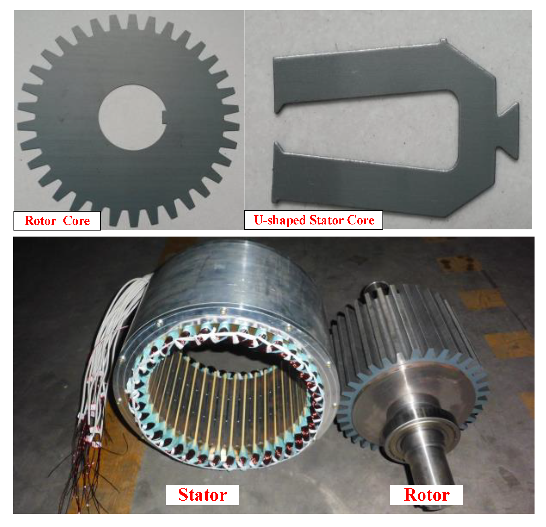
2. Topology and Initial Design of FSPM Generator

For a FSPM machine, the number of stator slots usually meets the requirement of Ps = m*Ncoil, where Ps is the stator slots number, m is the phase number, and Ncoil is the number of windings per phase. Considering the symmetry, Ncoil = 2k, where k is a positive integer. In this research, a nine-phase winding structure is adopted. Then, the number of stator teeth (slots) of a nine-phase FSPM generator can be 18, 36, 72, … etc. Generally, the number of rotor poles of a FSPM machine is selected to meet Pr = Ps ± 2, where Pr is the rotor teeth number. As the rotor tooth number increases, the fundamental armature current frequency will increase, resulting in the rise of iron loss. Therefore, normally, Pr < Ps is adopted. According to the conclusion of the literature [20], the 36-slot/34-pole FPSM machine has a lower cogging torque and higher torque density, Therefore, the combination of 36-slot/34-pole is selected in this study.
The topology and structure of the proposed nine-phase FSPM generator is shown in Figure 1. The winding distribution of the proposed FSPM structure is shown in Figure 1b. As far as the generator structure is concerned, there is no obvious differences between the nine-phase FSPM topology and a conventional three-phase machine except the numbers of stator slots and rotor poles, so the operation principle of the nine-phase FSPM machine is similar to a three-phase machine. The key specifications are in Table 1.

3. Optimization method

3.1. Parameter Model

Figure 2 shows the parameterized cross section of the model, where the U-shaped cores structure has been proved to exhibit better electromagnetic performance (Li et al., 2014). As shown, the model contains 11 parameters that are rationalized and confined according to Table 2.
As the dimensions are directly constrained by each other, it is not conducive for the optimization to directly use these dimensions. Therefore, some intermediate parameters are used to represent all the parameters, which are ksio, Khpm, Kwst, Kwrt, Kwpm, krty, and khrt, as listed in Table 3. In this design, the width coefficient of PM (Kwpm) adopts the minimum value which meets the requirements of magnetic circuit. In the existing design of the FSPM generator, the tooth root width of the rotor wrty is usually selected as twice the tooth width of the rotor wrt. Moreover, the tooth height of the rotor hrt is required to be 1.5 times greater than the tooth width wrt of the rotor. On this basis, the optimization will focus on the other four parameters ksio, Khpm, Kwst, and Kwrt. The main optimization objectives are torque under the same current density (Torque), torque per unit volume of PM (Torque/Vpm), and efficiency (Efi).

3.2. Stepwise Optimization Method

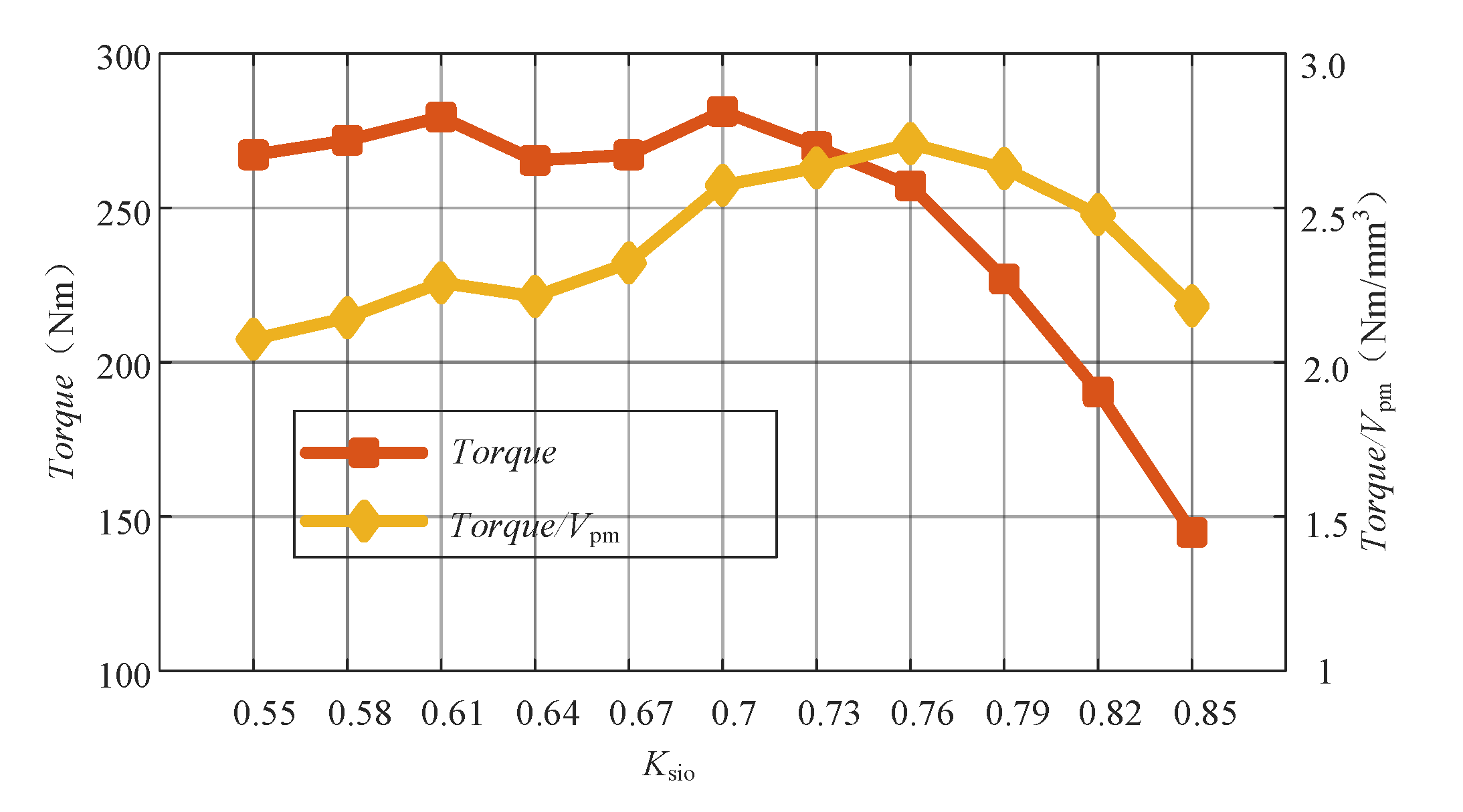
  • Step1: Split ratio optimization.
The split ratio (ksio) of the motor has a great influence on the torque of the FSPM. Air gap radius increases with the increase of split ratio, which is conducive to the torque output. However, a larger split ratio will also lead to the limitation of the stator space, and thereby result in the insufficient phase current under the fixed slot full rate and current density. Therefore, in the first step of optimization, the models with a different split ratio under fixed outer diameter are simulated, and the results are shown in Figure 3.
Taking the maximum electromagnetic torque as the optimization objective, the optimal split ratio of 36-slot/34-pole FSPM motor is 0.7. Although the volume of PM will gradually decrease with the increase of split ratio, which results in the decrease of electromagnetic torque. However, as shown in Figure 3, the decrease of electromagnetic torque per unit volume of PM (i.e., the output of PM per unit volume) is very small when the split ratio increases from 0.72 to 0.8. That is to say, the utilization rate of PM is almost unchanged with the decrease of the amount of PM. Therefore, the split ratio ksio of FSPM motor is determined to be 0.73 after considering the electromagnetic torque, PM consumption, and power factor.
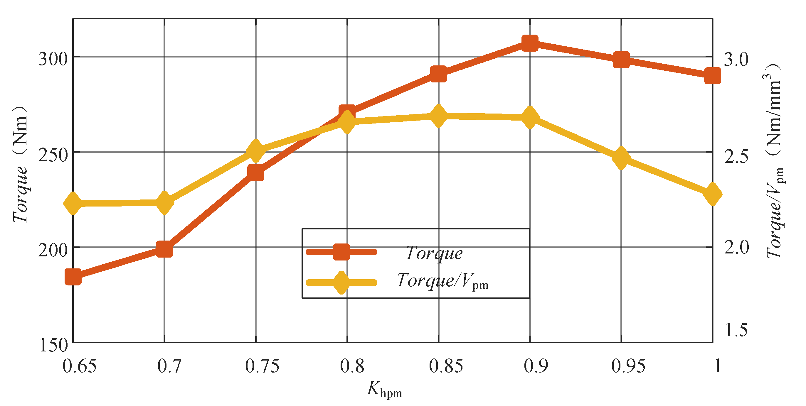
  • Step2: Permanent magnet size optimization.
The size and volume of PM directly determine the air gap flux density of the generator and affect motor power density and efficiency. In addition, the price of rare earth PM materials is high, and the output power per unit volume of PM is usually one of the important indicators to measure the quality of motor design. Therefore, the factors related to the determination of the structure size of the PM are analyzed for the optimization. In the previous FSPM design, the length of the permanent magnet is equal to the thickness of the stator in the radial direction. However, in this study, the design principle of using a U-shaped stator and shortening the length of the permanent magnet is proposed. Because there exists flux leakage in the original motor, reducing the length of the permanent magnet not only does not reduce the torque but also provides a higher unit permanent magnet torque. In this step, the permanent magnet length coefficient (Khpm, Khpm = hpm/(RsoRsi)) will be optimized.
The relationship between the permanent magnet length coefficient and torque is obtained by FEM simulation, as shown in Figure 4. The torque increases with the increase of Khpm until Khpm reaches 0.9. Then, torque decreases with the increase of Khpm. Torque/Vpm increases with the increase of Khpm when Khpm < 0.8. When Khpm is between 0.8 and 0.9, Torque/Vpm is unchanged. Considering Torque and Torque/Vpm, Khpm = 0.85 is selected in this design.
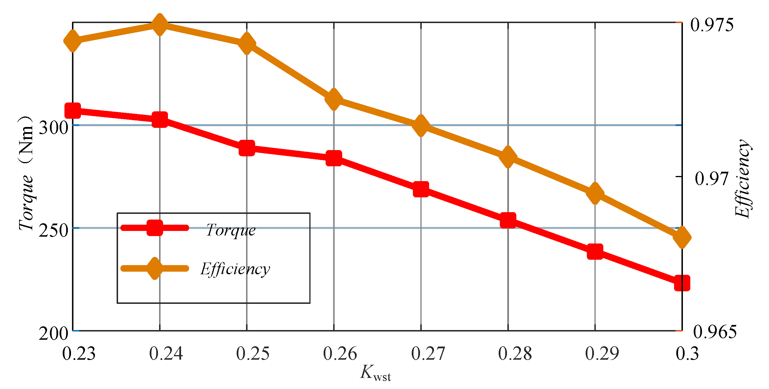
  • Step3: Stator slot size optimization.
The stator core size mainly affects the core loss and winding area. Therefore, Torque and Efi are considered as the objectives when optimizing the stator size. In this optimization step, the stator tooth width coefficient (Kwst, Kwst = wst/(Rsi * pi/18)) is selected as the parameter to be optimized. The stator tooth and stator yoke have the same magnetic flux, so the stator tooth width is equal to the stator yoke thickness (wsy = wst). The relationship between torque, Efficiency, and Kwst of FSPM is shown in Figure 5. The efficiency increases with the increase of stator tooth width when Kwst < 0.24 and decreases with the increase of stator tooth width Kwst > 0.24. The torque decreases with the increase of stator tooth width. Therefore, Kwst = 0.24 is selected in this design.
  • Step4: Rotor slot size optimization.
Without considering the magnetic field saturation, increasing the rotor tooth width will increase the permanent magnetic flux from the turning chain to the winding, and thereby increase the induced potential and electromagnetic torque. In this step, the Torque is compared under different tooth width coefficients Kwrt, wrty and hrt all change with Kwrt.
As shown in Figure 6, when the rotor tooth width coefficient Kwrt increases from 0.2 to 0.27, the id = 0 control method is adopted, the current density of the loading slot is 5.7 A/mm2, and the electromagnetic torque increases from 265 Nm to 297 Nm. However, as the magnetic field continues to increase, the torque hardly changes due to the saturation of the magnetic field. Therefore, to improve the electromagnetic torque, Kwrt between 0.27 and 0.29 is the better range.

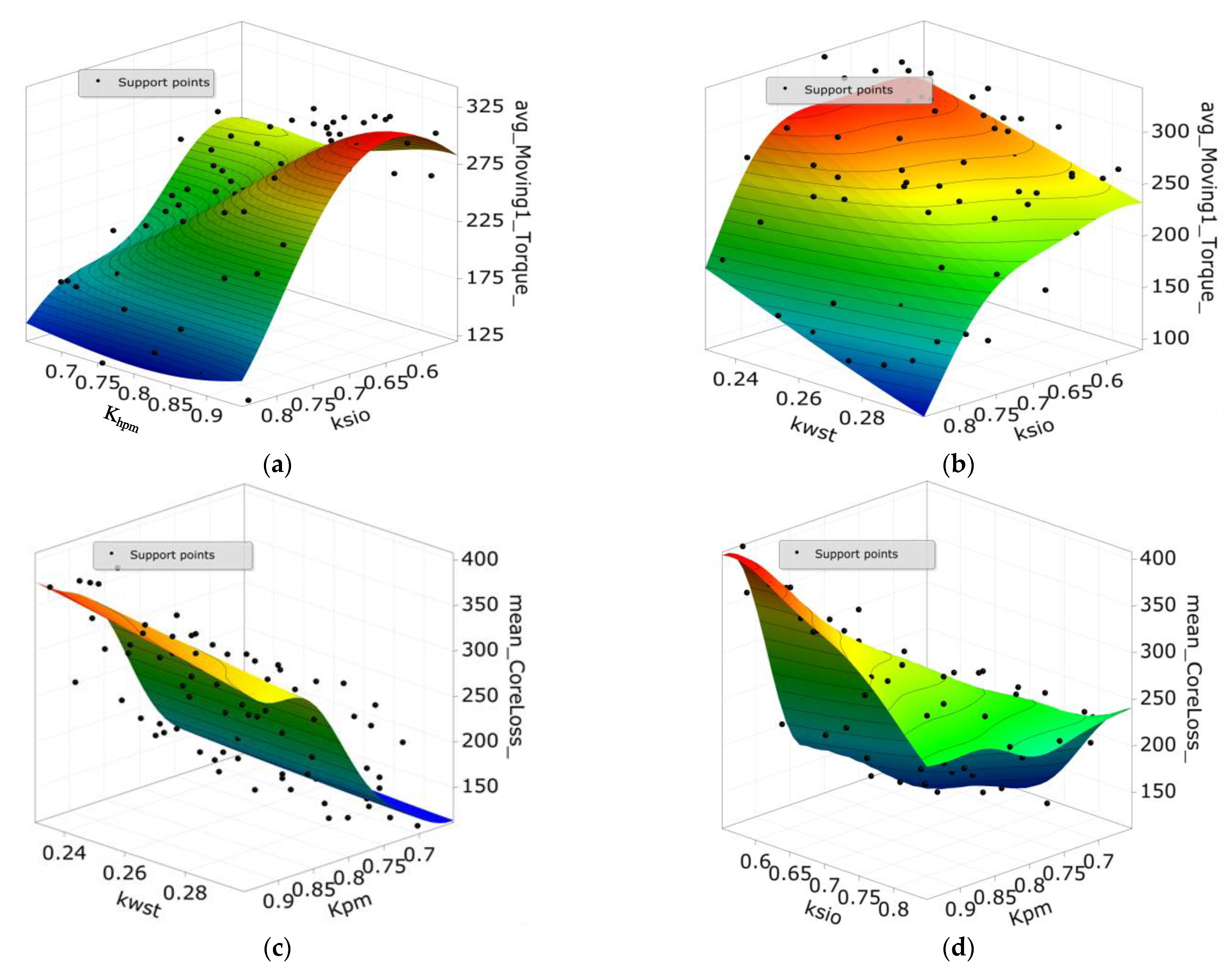
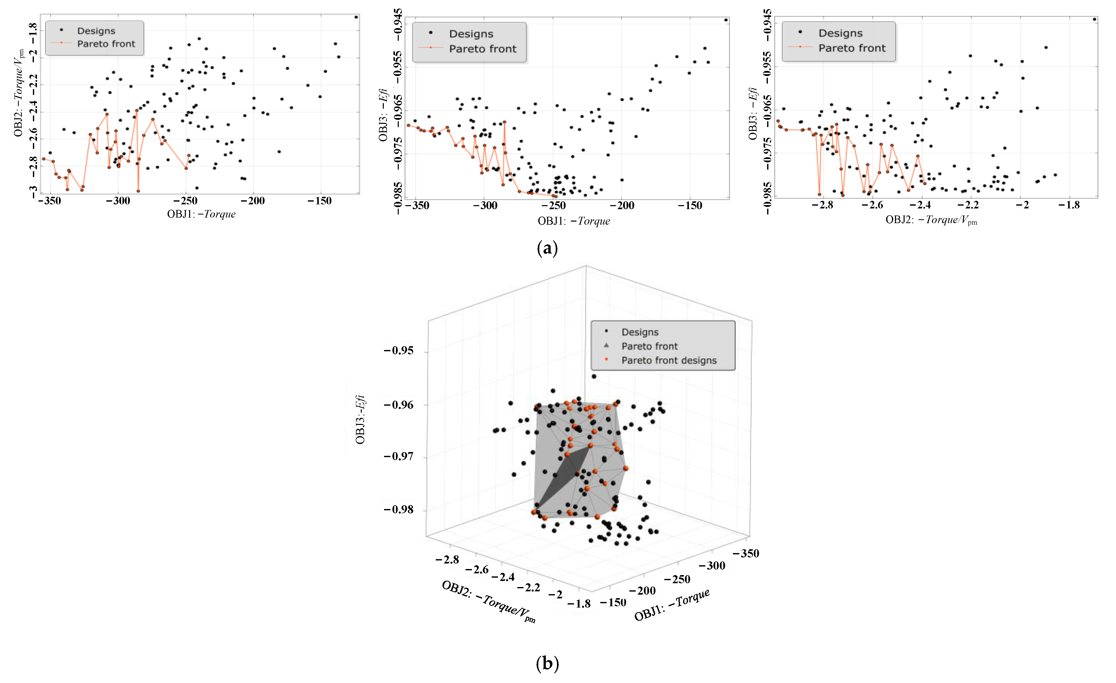
3.3. Global Optimization Method

Through the above optimization process, several main structural parameters of the motor can be determined. Considering that the motor is a multivariable, nonlinear, strong coupling energy conversion device, the change of each structural parameter will affect the optimal design range of other structural parameters. Therefore, employing the global optimization and multiparameter scanning at the same time to find a relatively optimal combination of structural parameters is another optimization idea.
To improve the efficiency of multi-objective optimization and realize trade-off design, some effective optimization algorithms are adopted and implemented in the optimization process. Among them, as a common algorithm, multi-objective genetic algorithm has the obvious characteristics of providing convenience to deal with multi-objective optimization problem and comprehensive trade-off problem, so it is widely used in solving multi-objective problems in the research field of motors. Therefore, based on the overall response surface calculation results, this paper introduces a multi-objective genetic algorithm to achieve effective optimization.
The objective function and related constraints are defined as follows:
Fun :   F [ Max [ T ] ,   Max [ E f i ] ,   Min [ T   /   V p m ] ] s . t . : { T e     200   Nm E f i     0 . 96
After the simulation of the sample points, the response surface (RS) of the output parameters can be established. Then, the response surface model is employed for the optimization. This will save a lot of calculation time. Figure 7 shows the RS Torque and core loss distributions with different inputs. The errors of the RS are less than 2%.
Figure 8 shows the Pareto solution results of the global optimization of the FSPM obtained by non-dominated sorting genetic optimization algorithm-II (NSGA II). The red line in the two-dimensional graph is a set of non-dominated solutions satisfying the two objectives. The surface on 3D Pareto solutions is the Pareto front. The black dot points meet the constraint requirements, while the gray points do not. As shown in the Pareto front, the maximum Torque can reach 350 N.m, Torque/Vpm can reach 2.8 N.m/m3, and Efi can reach 0.98. The value of each objective is superior to the stepwise optimization. However, there is no point can achieve three optimal values at the same time. The final design points can be selected according to the design preference.

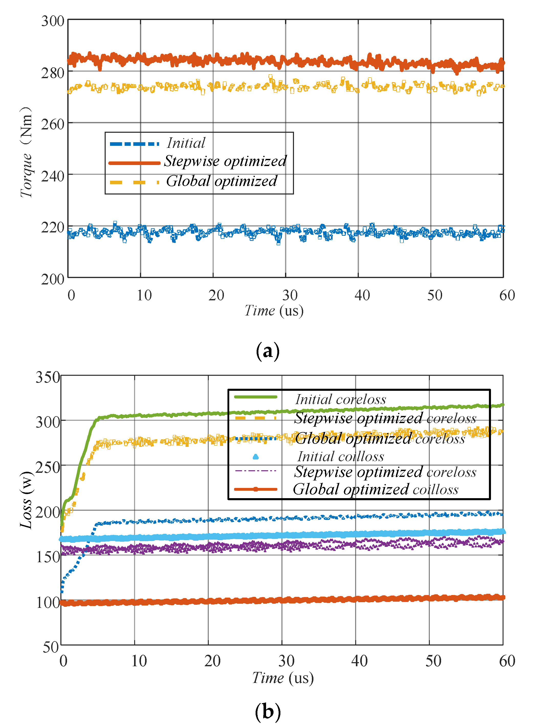
3.4. Comparison of Optimization Results
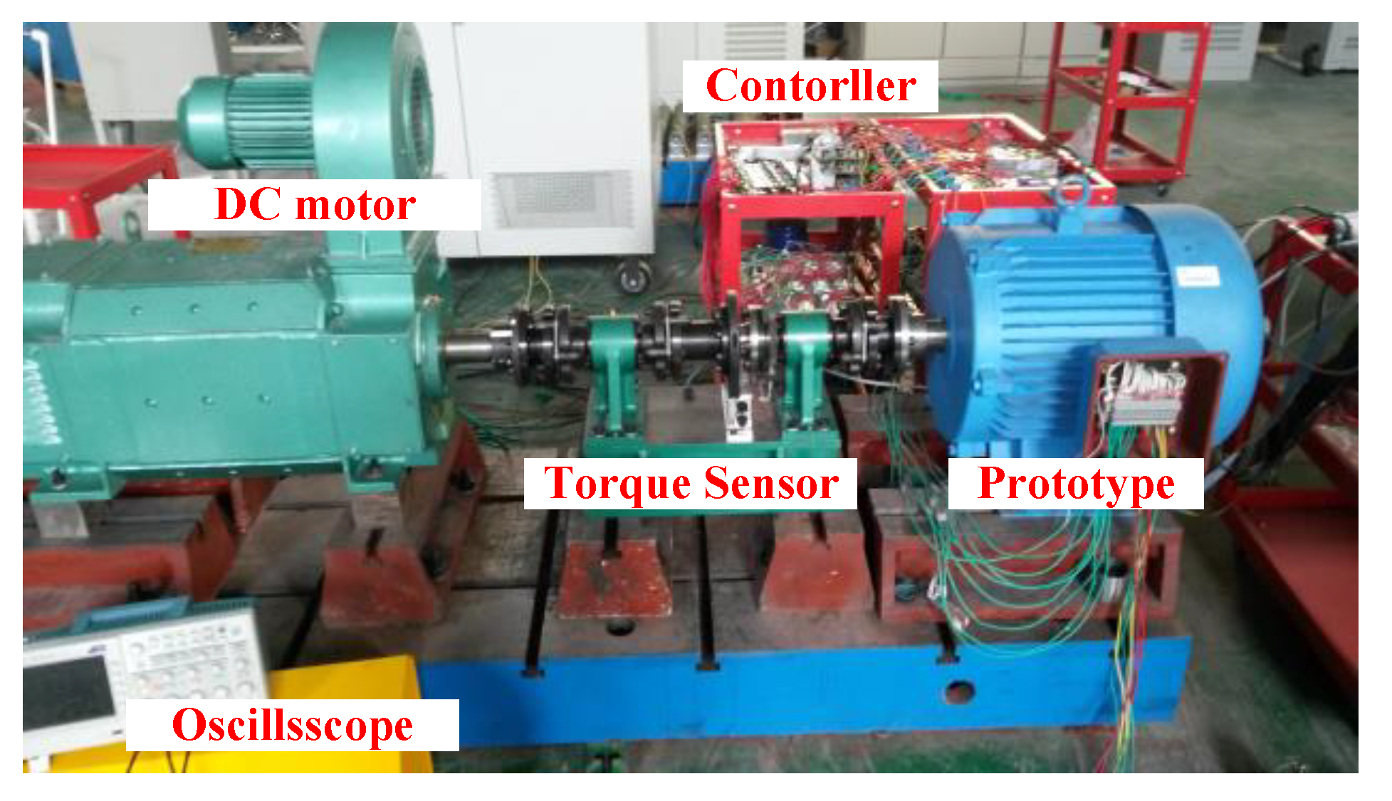
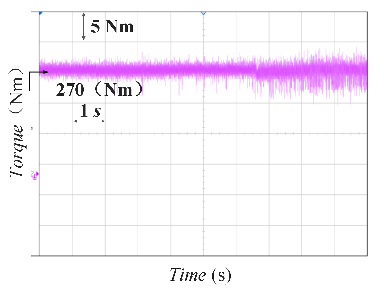
The parameter values and objective values of the two optimization methods before and after optimization are shown in Table 4. The detailed loss values are given in Table 5. The global optimization value is only a point on the Pareto front. The simulation waveforms of torque, core loss, and coil loss are shown in Figure 9. As shown, compared with the initial model, both optimization methods improve the electromagnetic performance significantly. In the aspect of Torque, the chosen design point of global optimization is lower than that of stepwise optimization. However, the Efi and Torque/Vpm of the design points selected on the Pareto front are better than those of stepwise optimization.
In terms of the amount of calculation required for optimization, the number of models that needs to be simulated for stepwise optimization is less than 50. Although the global optimization uses a response surface to replace the required model calculation in the iterative optimization process, it still needs to simulate no less than (45 = 1024) models to construct the response surface. Due to the use of response surface, iterative calculation does not need to calculate more finite element models. In traditional global optimization, NSGA II optimization requires calculate at least 50 iterations with 100 population (50 * 100 = 50,000). Generally speaking, the finite element models needing to be calculated in the global optimization method proposed in this paper are far less than the traditional optimization method of response surface, although it is more than 20 times of finite element model to be calculated in stepwise optimization.

4. Experiments

According to the above optimization design results, the design parameters of a 36-slot/34-pole FSPM generator are determined, as shown in Table 4 (Global optimization), and a prototype is made. Figure 10 shows the rotor core and U-shaped stator core of the FSPM prototype.
Figure 11 shows test platform. The test platform of the drive system, mainly including DC motor, DC load cabinet, torque sensor, FSPM generator, nine phases full bridge rectifier, DC regulated capacitor, resistance load, voltage, and current sensor and its sampling circuit, signal detection, and processing circuit, dspace1005 real-time simulation system.
Figure 12 shows the no-load induced potential waveforms of the A1 phase, B1 phase, and C1 phase at the speed of 600 r/min. Figure 12a is the simulation waveform. The simulation result of the no-load induced potential amplitude of each phase is 487.8 V, and the effective value is about 342 V. Figure 12b is the measured no-load induced potential waveform, and its amplitude is about 490 V, and the effective value is about 340 V. The error between the measured value and the simulation value mainly includes lamination coefficient, magnetic flux leakage coefficient estimation error, and processing error.
Figure 13 shows the torque waveform on the motor shaft measured by the HBM torque sensor when the speed is 600 r/min with the load loaded. The pulsation rate of the measured torque waveform is higher than the simulation value, mainly due to two reasons: first, the accuracy of the installation platform is not enough, and second, there are many electrical types of equipment in the experimental site, which cause interference to the control of the prime mover and pulsation when the prime mover itself rotates. The average torque is 275 Nm, according to which the input power of the prototype at the working point can be calculated as 17,804 W. After testing the voltage and current of each phase resistance load, the measured output power P = 17,272 W is calculated, that is, the measured efficiency is η = 96.8%. Excluding the measurement error, the measured efficiency is consistent with the estimated value in the last section, which meets the design requirements.

5. Conclusions

A nine-phase FSPM generator with 36 stator slots and 34 rotor poles is designed for wind power generation in this study. The influence of the pole number and slot number on the magnetic circuit of the motor is analyzed, and the appropriate pole number and slot number generator structure of the motor is selected. The influence of several key parameters on the important electromagnetic performances torque, torque per unit volume of PM, and efficiency are analyzed by finite element analysis. Two different optimization methods—stepwise optimization method and global optimization method—have been adopted in the optimization of the proposed FSPM generator. Both optimization methods can improve the performance of the motor effectively. There are no obvious differences between stepwise optimization and global optimization in the optimization of single performance. The number of models needed to be simulated for stepwise optimization is far less than that of global optimization, which means the stepwise optimization is suitable for the application of single-objective optimization. In contrast, the performance of the prototype after global optimization is more comprehensive. Global optimization is more conducive to the multi-objective optimization design of the electromagnetic system. When there are multiple parameters to be optimized and there is obvious mutual interference between the parameters, global optimization is a more appropriate optimization method. When the optimization objective is single or the parameters to be optimized are irrelevant, stepwise optimization is more appropriate. However, when there are too many parameters to be optimized, the amount of calculation required for global optimization is too large which will cost a lot of time. The proposed FSPM generator structure has the characteristics of high torque, low torque ripple, and high efficiency.

Author Contributions

Conceptualization, F.L. and X.Z.; methodology, F.L.; software, F.L.; validation, F.L. and X.Z.; formal analysis, F.L.; investigation, F.L.; data curation, F.L.; writing—original draft preparation, F.L.; writing—review and editing, F.L. and X.Z. All authors have read and agreed to the published version of the manuscript.

Funding

This research received no external funding.

Institutional Review Board Statement

Not applicable.

Informed Consent Statement

Not applicable.

Conflicts of Interest

The authors declare no conflict of interest.

References

  1. Polinder, H.; Ferreira, J.A.; Jensen, B.B.; Abrahamsen, A.B.; Atallah, K.; McMahon, R.A. Trends in wind turbine generator systems. IEEE J. Emerg. Sel. Top. Power Electron. 2013, 1, 174–185. [Google Scholar] [CrossRef]
  2. Zhu, Y.; Cheng, M.; Hua, W.; Wang, W. A novel maximum power point tracking control for permanent magnet direct drive wind energy conversion systems. Energies 2012, 5, 1398–1412. [Google Scholar] [CrossRef]
  3. Bhowmik, S.; Spee, R.; Enslin, J.H.R. Performance optimization for doubly fed wind power generation systems. IEEE Trans. Ind. Appl. 1999, 35, 949–958. [Google Scholar] [CrossRef]
  4. Liserre, M.; Cárdenas, R.; Molinas, M.; Rodriguez, J. Overview of multi-MW wind turbines and wind parks. IEEE Trans. Ind. Electron. 2011, 58, 1081–1095. [Google Scholar] [CrossRef]
  5. Sun, X.; Shi, Z.; Cai, Y.; Lei, G.; Guo, Y.; Zhu, J. Driving-Cycle-Oriented Design Optimization of a Permanent Magnet Hub Motor Drive System for a Four-Wheel-Drive Electric Vehicle. IEEE Trans. Transp. Electrif. 2020, 6, 1115–1125. [Google Scholar] [CrossRef]
  6. Abolhassani, M.T. A novel multiphase fault tolerant high torque density permanent magnet motor drive for traction application. IEEE Int. Conf. Electr. Mach. Drives 2005, 2005, 728–734. [Google Scholar]
  7. Sun, H.Y.; Wang, K. Effect of third harmonic flux density on cogging torque in surface-mounted permanent magnet machines. IEEE Trans. Ind. Electron. 2018, 66, 6150–6158. [Google Scholar] [CrossRef]
  8. Wang, K.; Gu, Z.Y.; Zhu, Z.Q.; Wu, Z.Z. Optimum injected harmonics into magnet shape in multiphase surface-mounted PM machine for maximum output torque. IEEE Trans. Ind. Electron. 2017, 64, 4434–4443. [Google Scholar] [CrossRef]
  9. Ojeda, J.; Simoes, M.G.; Li, G.; Gabsi, M. Design of a flux-switching electrical generator for wind turbine systems. IEEE Trans. Ind. Appl. 2012, 48, 1808–1816. [Google Scholar] [CrossRef]
  10. Hua, W.; Cheng, M.; Zhu, Z.Q.; Howe, D. Design of flux-switching permanent magnet machine considering the limitation of inverter and flux-weakening capability. In Proceedings of the Conference Record of the 2006 IEEE Industry Applications Conference Forty-First IAS Annual Meeting, Tampa, FL, USA, 8–12 October 2006. [Google Scholar]
  11. Zhao, J.; Yan, Y.; Li, B.; Liu, X.; Chen, Z. Influence of different rotor teeth shapes on the performance of flux switching permanent magnet machines used for electric vehicles. Energies 2014, 7, 8056–8075. [Google Scholar] [CrossRef] [Green Version]
  12. Zhang, G.; Hua, W.; Cheng, M. Steady-state characteristics analysis of hybrid-excited flux-switching machines with identical iron laminations. Energies 2015, 8, 12898–12916. [Google Scholar] [CrossRef] [Green Version]
  13. Yu, W.; Hua, W.; Zhang, Z. High-frequency core loss analysis of high-speed flux-switching permanent magnet machines. Electronics 2021, 10, 1076. [Google Scholar] [CrossRef]
  14. Thomas, A.S.; Zhu, Z.Q.; Owen, R.L.; Jewell, G.W.; Howe, D. Multiphase flux-switching permanent-magnet brushless machine for aerospace application. IEEE Trans. Ind. Appl. 2009, 45, 1971–1981. [Google Scholar] [CrossRef]
  15. Wei, H.; Zhou, L.K. Investigation of a co-axial dual-mechanical ports flux-switching permanent magnet machine for hybrid electric vehicles. Energies 2015, 8, 14361–14379. [Google Scholar]
  16. Chen, J.T.; Zhu, Z.Q. Influence of the rotor pole number on optimal parameters in flux-switching PM brushless AC machines by the lumped-parameter magnetic circuit model. IEEE Trans. Ind. Appl. 2010, 46, 1381–1388. [Google Scholar] [CrossRef]
  17. Chen, J.T.; Zhu, Z.Q.; Howe, D. Optimization of multi-tooth flux-switching PM brushless ac machines. In Proceedings of the 2008 18th International Conference on Electrical Machines, Vilamoura, Portugal, 6–9 September 2008. [Google Scholar]
  18. Sun, X.; Shi, Z.; Zhu, J. Multi-objective design optimization of an IPMSM for EVs based on fuzzy method and sequential Taguchi method. IEEE Trans. Ind. Electron. 2020, 68, 10592–10600. [Google Scholar] [CrossRef]
  19. Zhu, X.; Fan, D.; Mo, L.; Chen, Y.; Quan, L. Multiobjective optimization design of a double-rotor flux-switching permanent magnet machine considering multimode operation. IEEE Trans. Ind. Electron. 2018, 66, 641–653. [Google Scholar] [CrossRef]
  20. Li, F.; Hua, W.; Tong, M.; Zhao, G.; Cheng, M. Nine-phase flux-switching permanent magnet brushless machine for low-speed and high-torque applications. IEEE Trans. Magn. 2015, 51, 1–4. [Google Scholar]
Figure 1. Structure of the nine-phase FSPM generator. (a) 3-D structure; (b) Sectional view.
Energies 14 04754 g001
Figure 2. Key design geometric parameters of the FSPM generator.
Energies 14 04754 g002
Figure 3. Relationship between torque and split ratio of FSPM generator.
Energies 14 04754 g003
Figure 4. This is a figure. Schemes follow the same formatting.
Energies 14 04754 g004
Figure 5. Relationship between torque, efficiency, and Kwst of FSPM generator.
Energies 14 04754 g005
Figure 6. Relationship between torque and Kwrt of FSPM generator.
Energies 14 04754 g006
Figure 7. RS analysis of and Core loss distributions with inputs. (a) RS of torque distributions with Khpm and ksio. (b) RS of torque distributions with kwst and ksio. (c) RS of Core loss distributions with Khpm and kwst. (d) RS of Core loss distributions with Khpm and ksio.
Energies 14 04754 g007
Figure 8. 2D and 3D Pareto solutions of global optimization. (a) 2D Pareto solutions. (b) 3D Pareto solutions.
Energies 14 04754 g008
Figure 9. Comparison of torque and loss before and after optimization. (a) Simulated Torque wave of three design points. (b) Simulated coil loss and core loss wave of three design points.
Energies 14 04754 g009
Figure 10. Rotor core and stator core of the prototype.
Energies 14 04754 g010
Figure 11. 36-slot/34-pole FSPM prototype and test platform.
Energies 14 04754 g011
Figure 12. 36-slot/34-pole FSPM generator a set of three-phase (A1, B1, C1) No-load Back EMF @ 600 r/min: (a) Simulated. (b) Measured.
Energies 14 04754 g012
Figure 13. Measured torque under 5.7 A/mm2 current density @ 600 r/min.
Energies 14 04754 g013
Table 1. Key design parameters of the nine-phase FSPM generator.
SpecificationValue
Power17 kW
Speed600 r/min
Phase voltage230 V
Phase number9
Stack length172 mm
Stator outer diameter327 mm
Rotor bore diameter120 mm
Air gap length1 mm
Br of PMs1.2 T
Permeability of PM1.05
Table 2. Initial design parameters of the FSPM generator.
ParametersDescriptionValue
RsoStator outer radiusRso
RsiStator inner radiusRso × ksio
wstStator tooth widthKwst × Rsi × pi/18
wsyStator yoke widthKwst × Rsi × pi/18
wslStator slot opening widthRsi × pi /18 (1−2 × KwstKwpm)
hpmPM heightKhpm × (Rso-Rsi)
wpmPM widthKwpm × Rsi × pi/18
wslStator slot widthRsi × pi/18−2 × wstwpm
wrtRotor teeth tip widthKwrt (Rsi−1 mm) × pi/18
wrtyRotor teeth root widthkrty × wrt
hrtPM heightkhrt × wrt
Table 3. Initial intermediate parameters of the FSPM generator.
VariableDescriptionRange
ksiosplit ratio(0.55, 0.85)
KhpmHeight coefficient of PM(0.65, 1.0)
KwstStator tooth width coefficient(0.23, 0.30)
KwrtRotor tooth width coefficient(0.2, 0.3)
KwpmWidth coefficient of PM0.25
krtywrty/wrt2.0
khrthrt/wrt1.5
Table 4. Design parameters of the FSPM generator.
VariableInitialStepwise
Optimization
Global
Optimization
ksio0.80.720.70
Khpm0.920.850.76
Kwst0.250.240.24
Kwrt0.250.270.29
T217283273
T/Vpm2.42.652.75
Efi0.9450.9650.979
Torque ripple (%)2.452.222.24
PM Weight (kg)2.132.492.34
Table 5. Loss of each part before and after optimization.
VariableInitialStepwise
Optimization
Global
Optimization
PM loss (W)185162103
Stator core loss (W)231192110
Rotor core loss (W)898265
Copper loss (W)273305282
Publisher’s Note: MDPI stays neutral with regard to jurisdictional claims in published maps and institutional affiliations.

