Article

Recommendations for Running a Tandem of Adsorption Chillers Connected in Series and Powered by Low-Temperature Heat from District Heating Network

Department of Thermal Sciences, Wroclaw University of Science and Technology, Wyb. Wyspianskiego 27, 50-370 Wroclaw, Poland
*
Author to whom correspondence should be addressed.
Energies 2021, 14(16), 4791; https://doi.org/10.3390/en14164791
Submission received: 28 June 2021 / Revised: 28 July 2021 / Accepted: 2 August 2021 / Published: 6 August 2021
(This article belongs to the Special Issue Energy Storage Systems and Conversion Processes)

Abstract

:
In this paper, we investigate implications of running a cooling system of two silicagel/water adsorption chillers powered by a district heating network. The devices are connected in series, i.e., the heating water output from the primary chiller is directed to the secondary one. In consequence, the secondary device must deal with an even lower driving temperature and with temperature fluctuations caused by the primary device. We have evaluated three factors that influence the operation of those coupled devices: synchronization of their operating cycles, selection of their cycle time allocations (CTAs), and changing the heating water mass flow rate. Numerical analyses indicate that the performance of the secondary chiller drops significantly if the coupled devices that use the same CTA run asynchronously. The decrease is largest if the shift between the operating cycles is x = 0.375 and x = 0.875 . We found that it is possible to reduce the negative influence of the asynchronous operation by implementing different CTA in each chiller. The best performance is achieved if the primary chiller uses an adsorption time to desorption time ratio f = 1.0 and the secondary chiller uses f = 0.6–0.7.

1. Introduction

Tri-generation systems or combined cooling, heating and power systems (CCHPs), have become more popular during the past decades. These integrated systems offer higher thermal efficiency compared to traditional power generation systems, are more cost effective and have lower environmental impact. A typical CCHP system consists of a power generation unit working together with heating and cooling components (see Figure 1). The power plant generates electrical energy and ejects heat as waste. If the waste is used as a byproduct, the power plant becomes a co-generation plant. It can be installed locally or remotely, and, in the latter case, the waste heat is usually distributed using a district heating network. The recovered waste heat from the power generator is used to produce cooling or heating to satisfy local cooling and heating loads. An extensive review of modern CCHP technologies of both prime movers and supporting thermally activated subsystems has been conducted by Wu et al. [1] and, more recently, by Weiwu Ma et al. [2].
The majority of the literature on district heating and cooling systems focuses on the optimization of energy conversion technologies and operational strategies [1,2,3]. This also includes adsorption cooling as promising technology that can utilize low-temperature district heat for refrigeration.
Many advances in the field of adsorption cooling have been achieved in the last decades. Research areas included selection of the working pair [4,5], development of efficient advanced operating cycles [6,7], enhancement of heat and mass transfer in adsorption bed [6,7,8], accurate cycle time [9,10,11,12,13,14,15,16,17], etc. As a result, adsorption chillers are now successfully commercialized and can be implemented in district heating networks [13,18].
Powering adsorption chillers with district heat imposes several operational challenges. The most important one is the temperature of the heating water which should be kept low for economical reasons, i.e., at district heating design temperatures of 60–70 °C, the primary fuel usage is lowered by around 5–7% [3]. In addition, low supply temperatures mean that the electricity production in CHP-plants is higher, the heat recovery from industrial sites is higher, geothermal heat can be used more efficiently, and the coefficient of performance increases if heat pumps are used in heat generation [19]. The other important problem is the necessity to have the return temperatures as low as possible and to have temperature differences as large as possible. Otherwise, the increase of efficiency obtained by the lowered supply temperature will not compensate the increased cost of pumping and larger pipe diameters caused by the increased water flow [19].
Normally, for higher cooling demand, the best option is to install a larger adsorption chiller. On the other hand, commercialized chillers offer pre-designed cooling capacities. In more distributed and complex heating and cooling networks, it is economically more viable to increase the cooling output by adding additional off-the-shelf cooling devices instead of custom-designed bigger ones. The additional cooling device can be a compressor unit [20] or another sorption system. The latter is the topic of this article.
Two adsorption chillers can either run completely independently from each other (parallel configuration) or the operation of the second device is influenced by the output from the first one (serial configuration).
In the parallel configuration (see Figure 2), all the heat transfer fluids are evenly distributed between the chillers, and afterwards, the outputs are combined. However, to ensure normal operation of both devices, the heating water mass flow rate must be doubled. Otherwise both devices will run at a reduced capacity.
In the serial configuration (see Figure 3), the heating water output from the first chiller (called primary) is used as the heating water input for the second one (called secondary). The heating water mass flow rate remains the same, but as a consequence, the secondary chiller will always run below its nominal performance capability.
In both configurations, both chillers are cooled and produce chilled water independently. It is convenient to assume that both chilled water and cooling water mass flow rates always match the requirements of the chiller. Such an assumption is justified because these media are supplied locally and their mass flow rates are easily controlled, while the maximum heating water mass flow rate is usually controlled by the district heating operator.
Regardless of the case, the operating conditions of adsorption devices are very rigid, and both cooling capacity and performance heavily depend on the input temperature of the heating water. Therefore, in this paper, we numerically analyze the performance of two two-bed silica gel/water adsorption chillers that are powered by low-temperature heat from a district heating network. This study is focused on three factors that influence the performances of two adsorption chillers connected in series: synchronization of their operating cycles, consequence of using different cycle time allocations, and sensitivity to the change of mass flow rates of the media.
The chillers studied here are running one of the predefined cycle time allocations (CTAs): the symmetrical one [9] and the optimized one [10]. Additionally, we also evaluated the entire range of possible cycle time allocations varying the ratio between adsorption and desorption time f independently for every chiller. The outcome is a recommendation on how to set CTAs independently for each chiller in a way that will prevent a performance drop in the secondary device.

Two-Bed Cycle Time Allocations

Various researchers studied cycle time allocations in order to optimize performance of adsorption chillers [9,10,11,12,13,14]. In this paper, we discuss several possibilities: synchronized secondary chiller and unsynchronized secondary chiller, both cases with symmetric and asymmetric CTAs. The asymmetric CTAs were calculated for the adsorption to desorption time ratio f = 0.8. Additionally, the synchronized mode of operation was simulated with the f ratio in the range of 0.5–1.0. The total cycle time was always equal to 1000 s.
The first one is the symmetric CTA (lengths of adsorption and desorption phases are equal) which has been used and studied in depth by Saha et al. [9]. Recently, the symmetric CTA was modeled for a two-bed silica-gel/water adsorption chiller by Gado et al. [15]. These authors studied various cycle times for different operating conditions and found that the optimal desorption or adsorption time decreases when the heating and cooling water temperature increases and increases when cooling water temperature increases. For similar driving conditions as in this article, the authors proposed the total cycle time of 790 s. The symmetric CTA was experimentally evaluated for a three-bed sorption chiller by Sztekler [16]. This author found that the COP increases with time in the whole total cycle time range of 100–900 s, but the SCP reaches its maximum at 500 s.
The second one is the optimized CTA that has been introduced by Miyazaki et al. [10] to ensure smooth cooling output. This CTA improves the COP of a two-bed chiller and reduces fluctuations in the chilled water output temperature because, at any given moment, the evaporator is connected to one of the beds. The reason for the performance improvement is that in conventional adsorption chiller operation, the excess pre-heating/precooling time reduces the average cooling capacity. In the optimized CTA, the duration of adsorption phase (half of the cycle time) equals the sum of pre-heating, desorption and pre-cooling phases. As a result, a stable continuous cooling is achieved without sacrificing the effect of isosteric phases.
El-Sharkawy et al. [11] took a more generalized approach. The authors introduced an additional optimizing parameter: the ratio between adsorption and desorption time f. Glaznev and Aristov [12] showed that shortening the regeneration time improves the system efficiency because the desorption process is 2–3 times faster than adsorption. Working under this assumption, El-Sharkawy et al. [11] found that the ratio f that improves both capacity and the COP of a stand-alone two-bed chiller is approx. f 0.8 . Additionally, in this method, the proper control of the cooling and heating medium valves can increase the COP by enhancing the heat recovery from the media [13]. In case of the three-bed chiller, the optimal total cycle time producing the highest cooling capacity is shorter than in the case of a two-bed unit [14]. Lee et al. [17] observed that for a three-bed chiller (FAM-Z01/water), the adsorption to desorption ratio highly depends on the heating water temperature. For systems with heating water temperature of around 55 °C, the adsorption should be shorter than desorption, while for heating temperatures higher than 65 °C, it should be opposite—adsorption should be longer than desorption.
In the case of the symmetric CTA, the ratio f = 1.0 . All the other configurations are expressed with f < 1.0 in combination with different total cycle times and switch times. Assuming the total cycle time is t c y c l e = 1000 s and the switch time t s w i t c h = 50 s, the optimal CTA proposed by Miyazaki et al. [10] gives the ratio f = 0.8 which is approximately the optimized value found by El-Sharkawy et al. [11].

2. Materials & Methods

The set of ordinary differential equations that is described below in this section needs to be solved in order to simulate the dynamic behavior of an adsorption chiller. Simulations have been conducted for two identical two-bed chillers (detailed in Table 1) which operate at conditions presented in Table 2.
The results from our numerical simulations of a single device were verified by comparing to the calculation of Saha et al. [9] and experimental results provided by Boelman et al. [21]. The same example chiller has been used by El-Sharkawy et al. [11] in performance optimization.
In order to analyze operation of the two cooperating devices, we have developed a computer code that enables simultaneous solution of two sets of differential equations (one set for each chiller). The code has been written using the programming language Python 2.7, and the solution has been obtained using an ODE solver that is a part of the SciPy package.
The primary chiller is regenerated using heat from a district heating network at T h t f , i n = 65 °C. Both chillers use the same total cycle time t c y c l e = 1000 s, and the same length of isosteric phases t s w i t c h = 50 s. Due to the serial connection of the devices, the secondary chiller is driven by the outlet temperature from the primary one. Calculations were carried out under the assumption that chillers are standing next to each other and piping connections between them are very short (<1 m). Therefore, the heating water output from the first chiller immediately influences thermal behavior of the second one. In addition, the heating water mass flow rate is kept the same in both devices.

2.1. Mathematical Modeling

The equations used in the simulations are based on the lumped parameter model developed by Saha et al. [9], which enables accurate prediction of the system cooling capacity and performance. The authors numerically evaluated the cooling capacity and the COP of a two-bed adsorption chiller at various temperature levels and for symmetric CTA. The validity of their model has been verified experimentally [21]. In addition, those equations were used by El-Sharkawy et al. [11] for the optimization of a two-bed chiller and by Zajaczkowski [22] for the optimization of a three-bed chiller.
The detailed description of the model is described by Zajaczkowski [22]. The properties of the system used in the model are shown in Table 1, while the conditions are presented in Table 2. As the detailed model is available in a non open-access journal only, the authors have decided to present the model again.

2.1.1. Adsorber/desorber

The energy balance equation is expressed as in Equation (1). The refrigerant vapor accumulated in the beds and heat exchangers is neglected for the purpose of mass calculations. Heat losses are assumed to be negligible. The left-hand side represents the change of the sorption beds’ internal energy. The right-hand side includes the heat of adsorption/desorption, the heat supplied/removed by heat transfer fluid, and the heat carried by the refrigerant vapor (to/from another bed or from evaporator).
M a d s c p , a d s + M r e f c p , r e f + M m e t c p , m e t d T b e d d t =    M a d s Δ H a d s d q b e d d t + m ˙ h t f c p , w T h t f , i n T h t f , o u t             δ M a d s c p , v γ T b e d T e v a p + 1 γ T b e d T v d q b e d d t
The parameters of the heat transfer fluid (index h t f ) depend on the type of heat source or sink connected to the bed at the moment, i.e., cooling water if the bed is connected to a cooling tower or heating water if it is connected to a driving heat source. T e v a p is assumed to be equal to the evaporation temperature, as it is the temperature of vapor incoming from the evaporator. δ = 0 during isosteric phases and δ = 1 during adsorption and desorption phases. γ is equal 0 if the bed is connected to another bed and 1 if the bed is connected to the evaporator.
Outlet temperatures of the heat transfer fluid and the cooling water are calculated using the log mean temperature method as in Equation (2).
T h t f , o u t = T b e d + T h t f , i n T b e d exp U A b e d m ˙ h t f c p , w

2.1.2. Condenser

The balance equation for the condenser is given by Equation (3). The left-hand side of the equation is the change of the internal energy of the condenser. The right-hand side consists of the heat of condensation, the heat brought by the refrigerant vapor from the desorbing bed, and the heat removed by the cooling water.
M r e f c p , r e f + M c o n d c p , C u d T c o n d d t = L w M a d s d q d e s d t M a d s c p , r e f T d e s T c o n d d q d e s d t                      + m ˙ c o o l , c o n d c p , w T c o o l , i n T c o o l , o u t
The outlet temperature of the cooling water is calculated as in Equation (4).
T c o o l , o u t = T c o n d + T c o o l , i n T c o n d exp U A c o n d m ˙ c o o l , c o n d c p , w

2.1.3. Evaporator

The evaporator balance is calculated from Equation (5). The left-hand side of Equation (5) is the change of the internal energy of the evaporator. The right-hand side consists of the heat of evaporation, the heat carried by the liquid refrigerant returning from the condenser, and the heat from the chilled water.
M r e f c p , r e f + M e v a p c p , C u d T e v a p d t = L w M a d s d q a d s d t M a d s c p , r e f T c o n d T e v a p d q d e s d t                       + m ˙ c h i l l c p , w T c h i l l , i n T c h i l l , o u t
The outlet temperature of the chilled water is calculated as in Equation (6).
T c h i l l , o u t = T e v a p + T c h i l l , i n T e v a p exp U A e v a p m ˙ c h i l l c p , w
where U and A are the overall heat transfer coefficient and the heat transfer area in the condenser, respectively.

2.2. Adsorption Equilibrium

The Linear Driving Force (LDF) equation is an approximation of a solid diffusion model as a first-order linear differential equation [23]. It is described in Equation (7).
d q d t = 15 D s 0 R p 2 exp E a R T q * q
The adsorption equilibrium equation is chosen depending on the working pair. As there are several equilibrium models reported in the literature for silica gel/water properties, we used the equation recommended by Aristov et al. [24], as in Equation (8).
q * = 0.8841 + 3.0757 × 10 4 R T · ln p w T p s a t T
The refrigerant saturation pressure p s a t is calculated with the Antoine Equation (9).
p s a t = 133.32 · exp 18.3 3820 3820 T 46.1 T 46.1

2.2.1. Mass Balance

It is assumed that the condensed refrigerant is not stored in the condenser or the liquid receiver and is transferred to the evaporator. The equation for the refrigerant mass balance in the evaporator (10) takes into account uptake variations in all the beds.
d M r e f d t = M a d s d q a d s d t + d q d e s d t

2.2.2. Performance

The specific cooling power SCP of a chiller is defined as the cycle time averaged cooling capacity per unit mass of the adsorbent.
S C P = m ˙ c h i l l c p , w 0 t c y c l e T c h i l l , i n T c h i l l , o u t d t 2 · t c y c l e · M a d s
The COP is calculated as follows:
C O P = m ˙ c h i l l c p , w 0 t c y c l e T c h i l l , i n T c h i l l , o u t d t m ˙ h t f c p , w 0 t c y c l e T h t f , i n T h t f , o u t d t

3. Results and Discussion

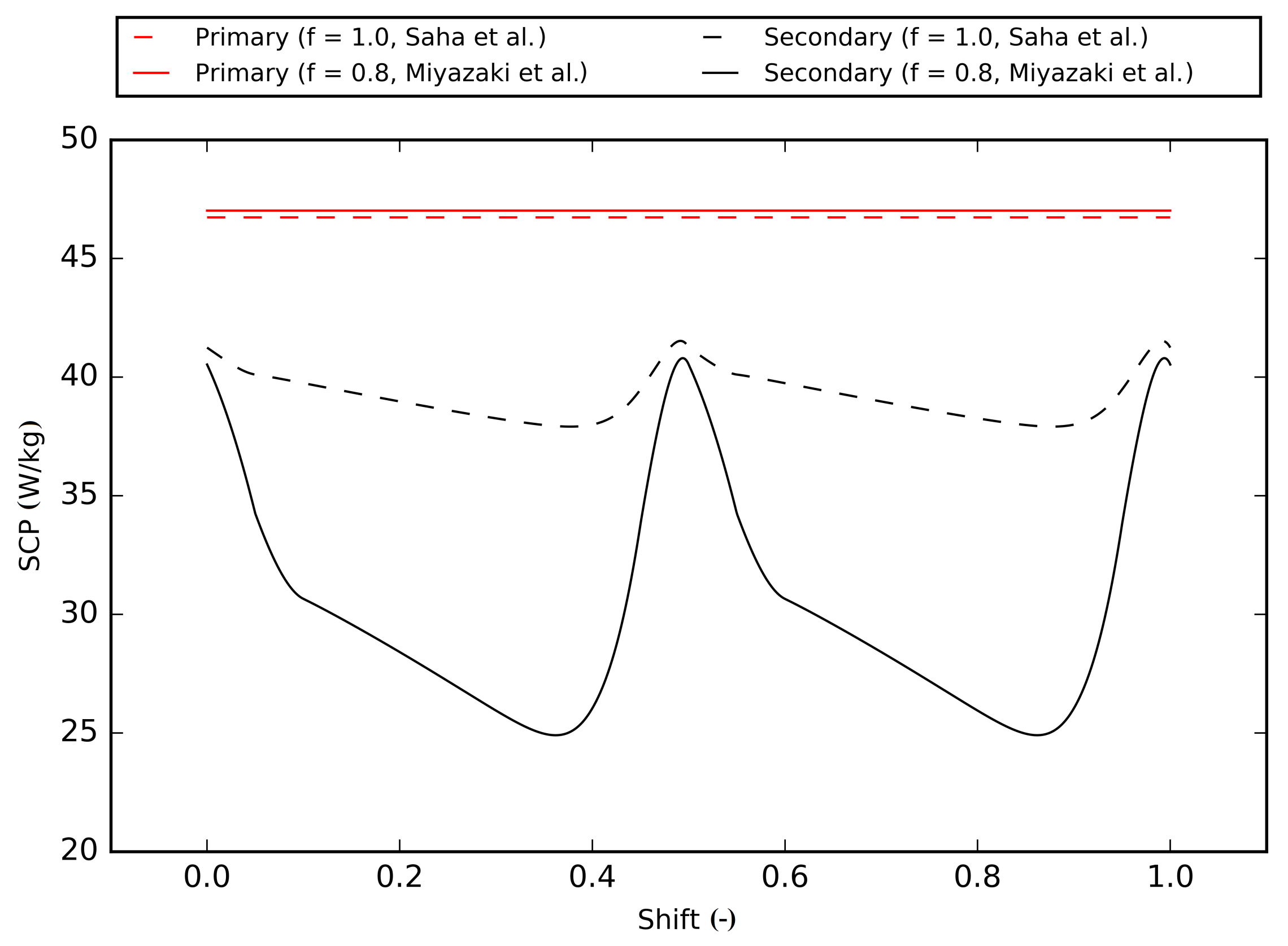
3.1. Synchronization of Operating Cycles

The analysis shows that one of the most important control factors for two chillers connected in series is the accuracy of their synchronization. Two chillers can operate either in perfect synchronization (their operating cycles start at the same moment) or out of phase (their operating cycles are shifted). In order to evaluate the influence of synchronization on performance of the secondary chiller, we introduced a dimensionless shift x that is calculated as the ratio of the difference between operating cycles (in seconds) divided by the total cycle time.
Figure 4 and Figure 5 show specific cooling capacities and performance coefficients of both chillers evaluated at different shifts x. The dashed line represents a pair of devices running the symmetric CTA, while the continuous line represents a pair of devices using the optimal CTA.
Constant values (horizontal lines above) express capacity and performance of the primary chiller, while varying values below represent capacity and performance of the secondary chiller. As expected, the optimal CTA suggested by Miyazaki et al. [10] increased both the SCP and the COP of the primary chiller. However, the overall gain is small because the driving temperature is only T h t f , i n = 65 °C.
A bigger difference can be noticed in the performance of the secondary chiller. If the operating cycles of the primary and the secondary chiller are in sync (i.e., phases in the working cycle begin at the same time, the shift is either x = 0 , x = 0.5 or x = 1 ), the tandem operates at its nominal condition and the performance drop in the second chiller is minimal. However, if the chillers run unsynchronized ( 0 < x < 0.5 or 0.5 < x < 1 ) the performance reduction of the secondary unit is significant. In the worst case, the SCP is reduced by 18.9% (the symmetric CTA) and by 47.0% (the optimal CTA), while the COP is reduced by 9.6% and by 61.3%, correspondingly. Regardless of the CTA, the SCP and the COP drop the most if the operating cycles are shifted by x = 0.375 or x = 0.875 .
This is because the outlet heat transfer fluid temperature of the primary chiller is the inlet temperature of the secondary one and it is changing in time. If both chillers are unsynchronized, then the outlet heat transfer fluid temperature drop caused by the bed change in the primary chiller disturbs the desorption in the secondary chiller.

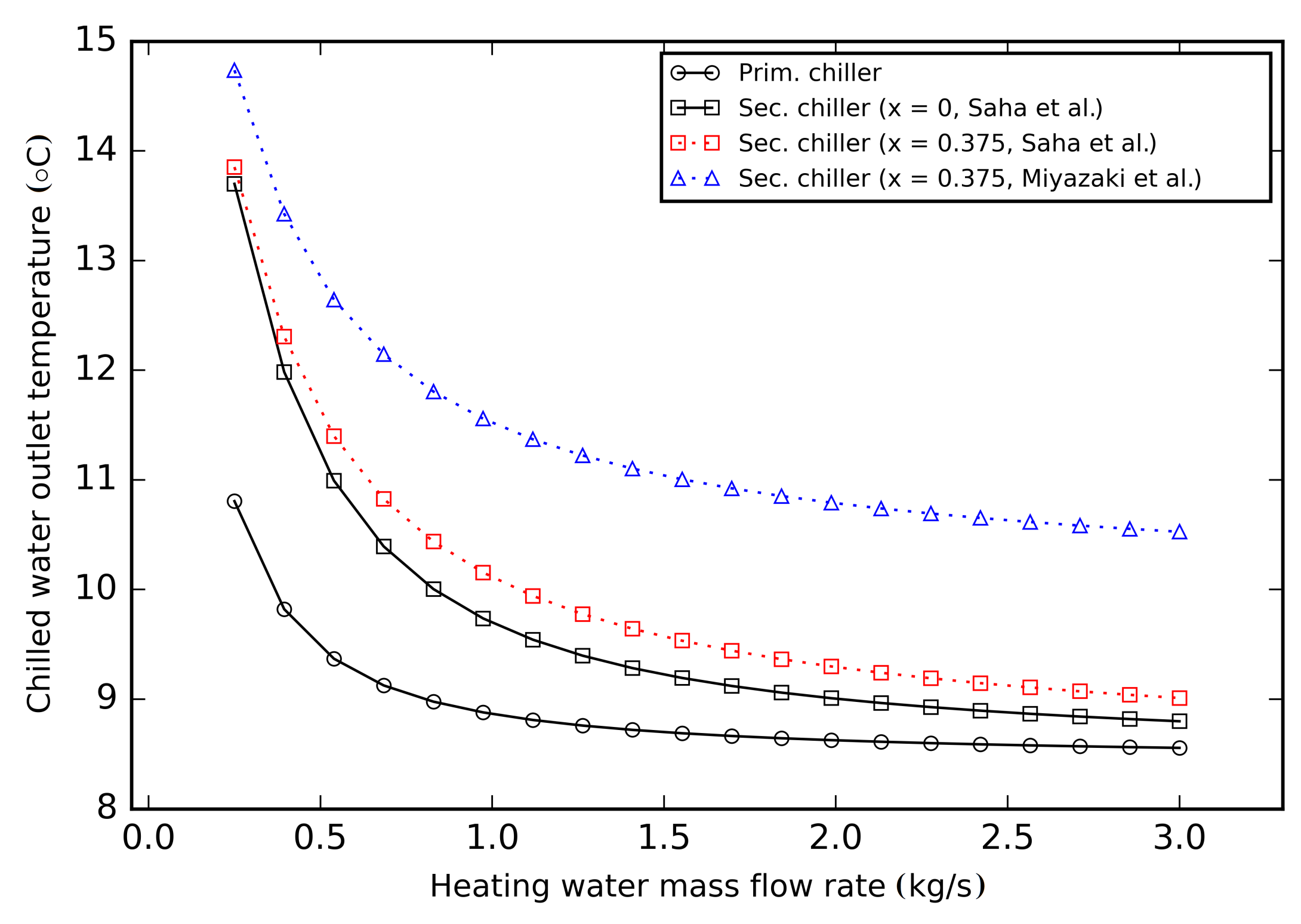
3.2. Heating Water Mass Flow Rate

On the side of the district heating operation, the temperature of the returning water is very important. According to fundamental principles of heat transfer, the low heating water mass flow rate yields a higher temperature drop, and the lowest possible return temperature is desired for optimal operation of the district heating network. On the other hand, the low heating water mass flow rate will not only make the secondary chiller to run at even lower driving temperature, but also force it to deal with significant temperature fluctuations. As a consequence, both the cooling capacity and the performance of the secondary chiller will be significantly reduced, while the chilled water outlet temperature will raise.
In the case of the example chiller studied in this paper, the heating water mass flow was analyzed in the range 0.2–3.0 kg/s, and the values of all the other temperatures and mass flows were set according to Table 2. The temperature at each simulated point is calculated as an average for a single operating cycle after steady state conditions were achieved.
The numerical study shows that the heating water mass flow rate is the most important factor that controls the temperature of return. The heating water outlet temperatures in the primary chiller, synchronized secondary chiller and unsynchronized secondary chiller (for both analyzed CTAs) are presented in Figure 6. Results show that the heating water outlet temperature in the secondary chiller is almost independent of the CTA and rather insensitive to the shift, i.e., the difference between outlet temperatures in different configurations of shifts and CTAs never exceeds 1 °C.
Chilled water outlet temperatures that can be achieved by the analyzed tandem of chillers at different heating water mass flow rates are shown in Figure 7. Lowered driving temperatures reduce the cooling effect in the secondary chiller, and, in consequence, the chilled water outlet temperature will be always higher than in the primary one.
In the analyzed example, the driving temperature T h t f , i n = 65 °C is the reason for the primary chiller to be unable to produce cooling at temperatures below 8.5 °C (Figure 7, regardless of the heating water mass flow rate. At the same time, the chilled water temperature output from the synchronized secondary chiller is approx. 9–10 °C. The asynchronous operation will increase the output temperature further by approx. 0.5 °C in case of the symmetric CTA, and approx. 2 °C in case of the optimal CTA.
Figure 8 and Figure 9 show the SCP and the COP evaluated for the same example pair of devices and the same range of heating water mass flow rates.
As a rule, the SCP and the COP increase with increasing heating water mass flow rate and both values asymptotically approach the maximum for analyzed system. For example, if both devices run synchronously using the symmetrical CTA ( f = 1.0 ) , the SCP of the primary chiller stabilizes at approx. 47–48 W/kg and, for the secondary one, at approx. 44–46 W/kg. The maximum COP that is achieved by the primary chiller is 0.32, and the secondary one reaches 0.31.
If both chillers use the symmetric CTA ( f = 1.0 ) and run synchronized then the decrease of the SCP in the secondary one is 35.0% at 0.5 kg/s, 16.7% at 1.0 kg/s, and 7.1% at 2.0 kg/s. If their phases are shifted, the SCP in the secondary unit drops further by 8.8%, 8.2%, and 6.4%, correspondingly. Reductions are significantly higher if the optimal CTA ( f = 0.8 ) is implemented, i.e., the SCP in the secondary chiller drops by 70.7% at 0.5 kg/s, 52.3% at 1.0 kg/s, and 40.3% at 2.0 kg/s.
If both devices run in synchronization the COP of the secondary chiller drops by 21.4% at 0.5 kg/s, 9.2% at 1.0 kg/s, and approx. 4.5% at 2.0 kg/s. If the devices become unsynchronized the performance reduction of the secondary chiller depends on the CTA. For the symmetrical CTA ( f = 1.0 ) , it is 26.3% at 0.5 kg/s, 13.1% at 1.0 kg/s, and 6.6% at 2.0 kg/s, while for the optimal CTA ( f = 0.8 ) , it is significant 71.5% at 0.5 kg/s, 62.2% at 1.0 kg/s, and 59.4% at 2.0 kg/s.
In contrast to the heating water outlet temperature profiles presented in Figure 6, the SCP and the COP of the secondary chiller are sensitive to both the chosen CTA and to the shift in the context of heating water mass flow rate as seen in Figure 8 and Figure 9. The reduction of the performance is significant and it cannot be balanced by a simple increase of the heating water mass flow rate.

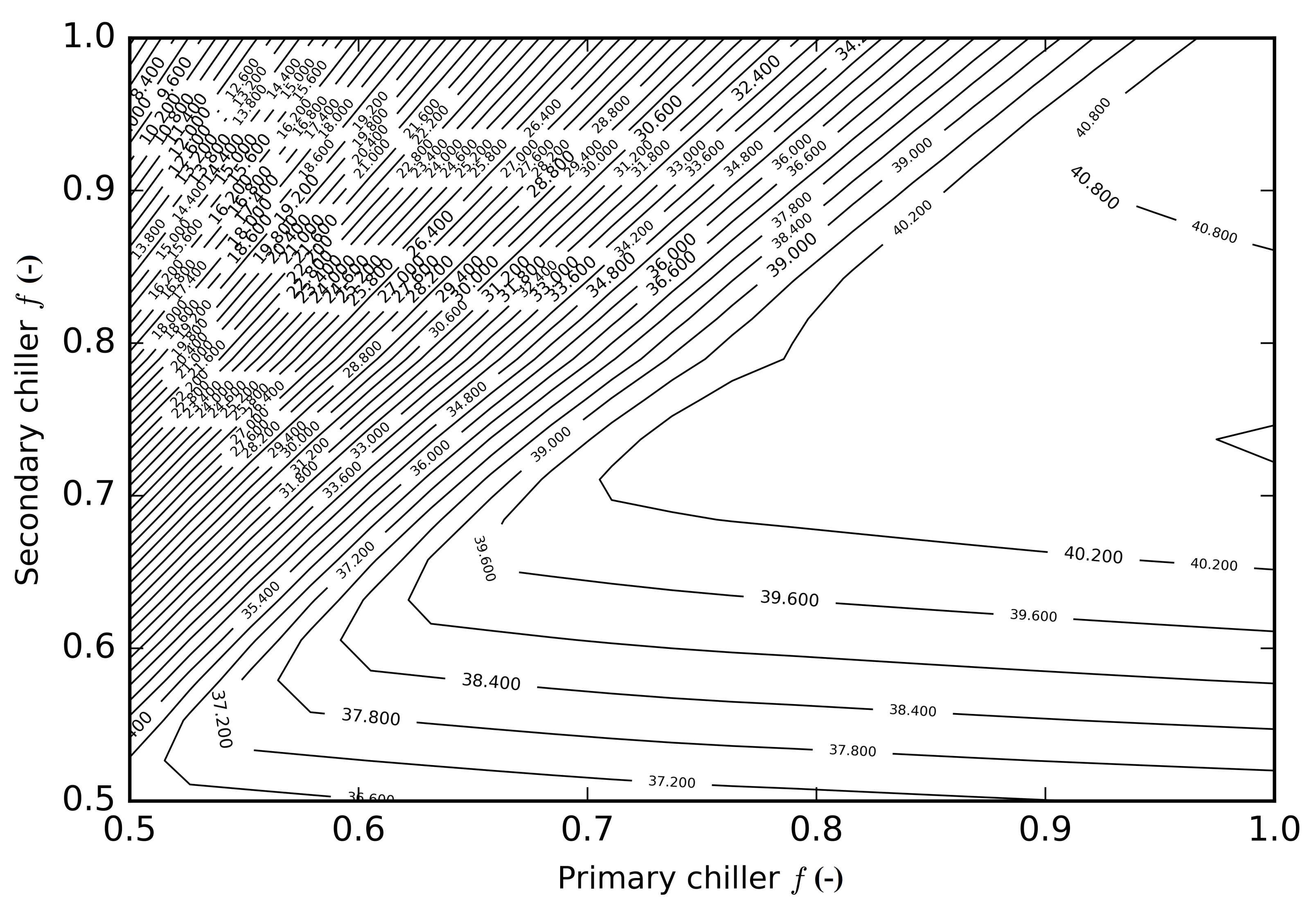
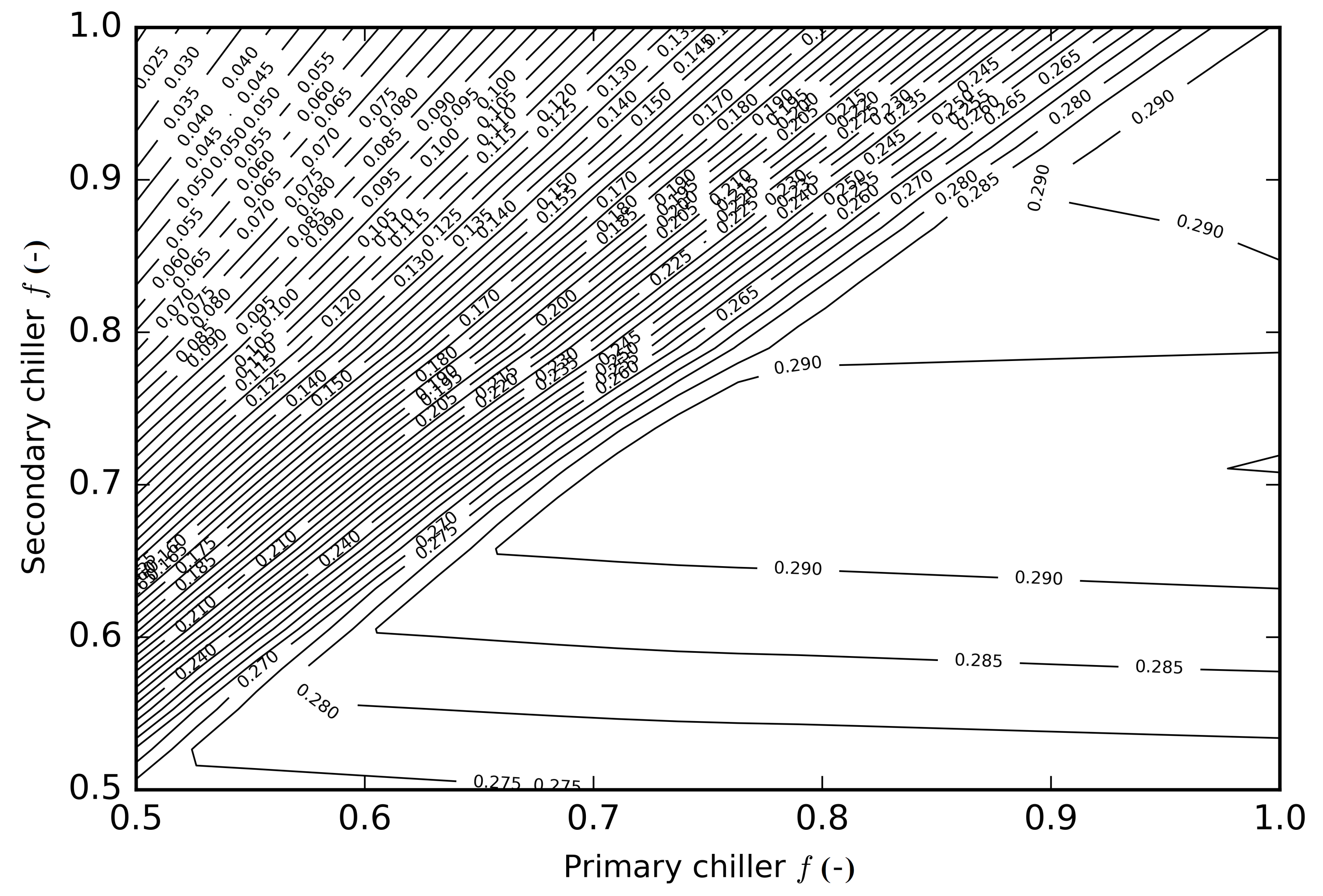
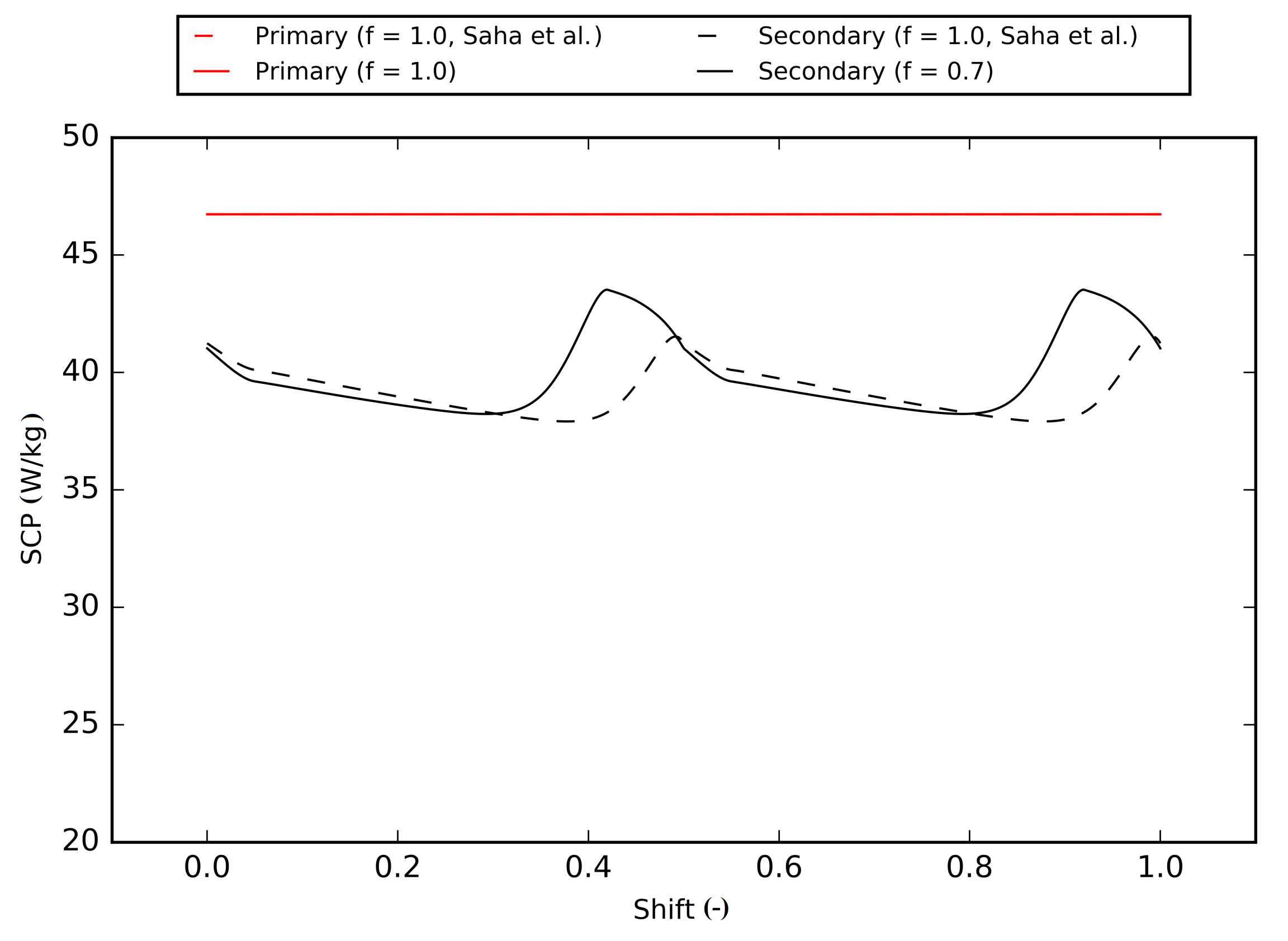
3.3. Secondary Chiller Performance Optimization

Based on above presented analyses, we determined that regardless of synchronization (the shift), the type of CTA, or the value of the heating water mass flow rate, when two identical adsorption chillers are connected in series, the result is a reduced performance of the secondary device.
For this reason, we decided to optimize the operation of the secondary chiller by adjusting the CTA in each device separately. The heating water mass flow rate stays the same (see Table 2) and both devices remain identical in technical terms (e.g., mass of adsorbent, size of heat transfer area, etc.). The performance optimization has been carried out using a set of for-loops that change the ratio f in the range 0.5–1.0 set separately for each chiller (as f 1 and f 2 ).
The results for synchronized operation ( x = 0 ) are presented in Figure 10 and Figure 11, while the results for unsynchronized operation ( x = 0.375 ) are presented in Figure 12 and Figure 13. Results for two CTAs that were discussed earlier can also be found in the presented contour plots: the symmetric CTA in which the primary chiller f 1 = 1.0 and the secondary chiller f 2 = 1.0 ), and the optimal CTA in which the primary chiller f 1 = 0.8 , the secondary chiller f 2 = 0.8 ). The presented diagrams show that the values of both the SCP and the COP of the secondary chiller are always higher if the ratio f 1 approaches one.
If both devices work synchronously, they can use the same CTA (i.e., f 1 = f 2 ) without causing significant negative impact to the secondary chiller. In such a case, it is desired to use the optimal CTA by Miyazaki et al. [10] or the optimized adsorption/desorption time ratio f by El-Sharkawy et al. [11] to increase performance of the primary chiller, and the performance of the secondary chiller will not suffer significantly (see also Figure 4 and Figure 5). Unfortunately, if for any reason this pair of devices starts to run asynchronously, a significant performance drop is unavoidable (values in Figure 10 and Figure 11 vs. values in Figure 12 and Figure 13). The asynchronous work may be due to wrong programming of the controllers which did not take into account the real distance between the chillers and, thus, the time needed for the heat transfer fluid to flow from the first chiller to the second one.
The degree of performance deterioration is the smallest if the ratio f 1 for the primary chiller approaches 1.0. It means that in order to keep performance of the secondary chiller as high as possible, the primary chiller should use the symmetric CTA (i.e., f 1 = 1.0 ).
At the same time, the desired adsorption/desorption time ratio for the secondary chiller is approx. f 2 = 0.6 0.7 . Such a configuration will ensure the best possible performance of the coupled devices. Figure 14 and Figure 15 show how this new pair of cycle time allocation (set independently for each chiller) influences the performance in the entire range of phase shifts. Instead of a significant drop of the SCP and the COP, it is possible not only to prevent reduction but even to achieve an actual performance increase.
The COP increase is possible for both, symmetric and optimized CTAs, but is the highest if the secondary chiller works under the optimized CTA with f 2 ratio of 0.7 and the dimensionless shift 0.9 or 0.4. The efficiency of the secondary chiller is higher, even though the heat transfer fluid inlet temperature is lower than for the first chiller, but its total cooling power will be lower, as the SCP drops. For the lower desorption temperatures, the heat needed for the regeneration is smaller as there is less refrigerant particles that will leave the sorbent. Additionally, less heat needs to be added for the heating of additional metal components of the heat exchanger.

4. Conclusions

In this paper, we conducted a comprehensive numerical analysis of a tandem of adsorption chillers that are working connected in series. The conclusion is a set of recommendations that will ensure optimal operation of the secondary device.
  • The performance of a single stand-alone chiller is higher if it uses the optimal CTA. On the other hand, if two identical chillers are connected in series, and the accuracy of their synchronization cannot be controlled, the performance of the second device will be higher if both units use the symmetric CTA instead. The maximum performance drop is observed for x = 0.375 and x = 0.875 .
  • The heating water outlet temperature in the secondary chiller is mainly controlled by the heating water mass flow rate. At the same time, this temperature is almost independent of the CTA that has been used in both chillers, and its sensitivity to the shift is very small. Regardless of the configuration, the difference between simulated outlet temperatures was always less than 1 °C.
  • The degree of performance deterioration in the secondary chiller is the smallest if the adsorption/desorption time ratio in the primary chiller f 1 approaches 1.0, i.e., the primary chiller should use the symmetric CTA.
  • The optimal adsorption/desorption time ratio for the secondary chiller is between f 2 = 0.6–0.7 (approx. 0.7 for the maximum SCP, and approx. 0.6 for the maximum COP).

Author Contributions

Conceptualization, T.H.; methodology, T.H. and B.N.; software, T.H.; validation, B.N.; formal analysis, T.H.; investigation, B.N.; resources, T.H.; data curation, T.H. and B.N.; writing—original draft preparation, T.H.; writing—review and editing, B.N.; visualization, B.N.; supervision, T.H.; project administration, T.H. All authors have read and agreed to the published version of the manuscript.

Funding

This research received no external funding.

Institutional Review Board Statement

Not applicable.

Informed Consent Statement

Not applicable.

Data Availability Statement

The data presented in this study are available on request from the corresponding author.

Conflicts of Interest

The authors declare no conflict of interest.

Abbreviations

The following abbreviations are used in this manuscript:
CCHPCombined Cooling, Heat and Power
CHPCombined Heat and Power
COPCoefficient of Performance
CTACycle Time Allocation
SCPSpecific Cooling Power
Nomenclature
Aheat transfer area m 2
cspecific heat J / kgK
D s 0 pre-exponential constant m 2 / s
E a activation energy of surface diffusion J / mol
Llatent heat J / kg
Mmass kg
m ˙ mass flow ratekg/s
ppressurePa
qadsorbed amount of refrigerant vapor kg / kg
q * vapor adsorbed at equilibrium kg / kg
Runiversal gas constant m
R p adsorbent particle size m
TtemperatureK
Uheat transfer coefficient W / m 2 K
δ = 0 isosteric phase indicator-
Δ H a d s isosteric heat of adsorption J / kg
γ heat exchanger indicator-
Subscripts
a d s adsorption/adsorber
c h i l l chilled medium
c o n d condensation/condenser
c o o l cooling fluid
e v a p evaporation/evaporator
h t f heat transfer fluid
i n inlet
m e t , A l referring to other metallic components (aluminum fins)
m e t , C u referring to other metallic components (copper tubes)
o u t outlet
r e f refrigerant
s a t saturation
vvapor from another bed
wwater

References

  1. Wu, D.; Wang, R. Combined cooling, heating and power: A review. Prog. Energy Combust. Sci. 2006, 32, 459–495. [Google Scholar] [CrossRef]
  2. Ma, W.; Fan, J.; Fang, S.; Hassan, N.; Zhang, Y.; Wu, X.; Li, Y.; Hu, R.; Liu, G. Energy efficiency indicators for combined cooling, heating and power systems. Energy Convers. Manag. 2021, 239, 114187. [Google Scholar] [CrossRef]
  3. Ommen, T.; Markussen, W.B.; Elmegaard, B. Lowering district heating temperatures—Impact to system performance in current and future Danish energy scenarios. Energy 2016, 94, 273–291. [Google Scholar] [CrossRef] [Green Version]
  4. Wang, L.; Wang, R.R.; Oliveira, R. A review on adsorption working pairs for refrigeration. Renew. Sustain. Energy Rev. 2009, 13, 518–534. [Google Scholar] [CrossRef]
  5. Shmroukh, A.N.; Ali, A.H.H.; Ookawara, S. Adsorption working pairs for adsorption cooling chillers: A review based on adsorption capacity and environmental impact. Renew. Sustain. Energy Rev. 2015, 50, 445–456. [Google Scholar] [CrossRef]
  6. Li, X.; Hou, X.; Zhang, X.; Yuan, Z. A review on development of adsorption cooling—Novel beds and advanced cycles. Energy Convers. Manag. 2015, 94, 221–232. [Google Scholar] [CrossRef]
  7. Choudhury, B.; Saha, B.B.; Chatterjee, P.K.; Sarkar, J.P. An overview of developments in adsorption refrigeration systems towards a sustainable way of cooling. Appl. Energy 2013, 104, 554–567. [Google Scholar] [CrossRef]
  8. Sharafian, A.; Bahrami, M. Assessment of adsorber bed designs in waste-heat driven adsorption cooling systems for vehicle air conditioning and refrigeration. Renew. Sustain. Energy Rev. 2014, 30, 440–451. [Google Scholar] [CrossRef]
  9. Saha, B.; Boelman, E.; Kashiwagi, T. Computer simulation of a silica gel-water adsorption refrigeration cycle- the influence of operating conditions on cooling output and COP. ASHRAE Trans. 1995, 101, 348–357. [Google Scholar]
  10. Miyazaki, T.; Akisawa, A.; Saha, B.B.B.; El-Sharkawy, I.I.; Chakraborty, A. A new cycle time allocation for enhancing the performance of two-bed adsorption chillers. Int. J. Refrig. 2009, 32, 846–853. [Google Scholar] [CrossRef]
  11. El-Sharkawy, I.I.; Abdelmeguid, H.; Saha, B.B. Towards an optimal performance of adsorption chillers: Reallocation of adsorption/desorption cycle times. Int. J. Heat Mass Transf. 2013, 63, 171–182. [Google Scholar] [CrossRef]
  12. Glaznev, I.; Aristov, Y. The effect of cycle boundary conditions and adsorbent grain size on the water sorption dynamics in adsorption chillers. Int. J. Heat Mass Transf. 2010, 53, 1893–1898. [Google Scholar] [CrossRef]
  13. Chorowski, M.; Pyrka, P.; Rogala, Z.; Czupryński, P. Experimental Study of Performance Improvement of 3-Bed and 2-Evaporator Adsorption Chiller by Control Optimization. Energies 2019, 12, 3943. [Google Scholar] [CrossRef] [Green Version]
  14. Zajaczkowski, B. Performance analysis and cycle time optimization of a single evaporator three-bed solid-sorption refrigeration system driven by low-temperature heat source. In Proceedings of the 24th IIR International Congress of Refrigeration, Yokohama, Japan, 16–22 August 2015; International Institute of Refrigeration, International Institute of Refrigeration: Yokohama, Japan, 2015; Volume 1, pp. 1–8. [Google Scholar]
  15. Gado, M.; Elgendy, E.; Elsayed, K.; Fatouh, M. Performance enhancement of an adsorption chiller by optimum cycle time allocation at different operating conditions. Adv. Mech. Eng. 2019, 11. [Google Scholar] [CrossRef]
  16. Sztekler, K. Optimisation of Operation of Adsorption Chiller with Desalination Function. Energies 2021, 14, 2668. [Google Scholar] [CrossRef]
  17. Lee, W.S.; Park, M.Y.; Lee, S.S.; Duong, X.Q.; Cao, N.V.; Kwon, O.K.; Chung, J.D. Effect of adsorption and desorption cycle time allocation on the performance of an adsorption chiller. J. Mech. Sci. Technol. 2021, 35, 323–331. [Google Scholar] [CrossRef]
  18. Halon, T.; Pelinska-Olko, E.; Szyc, M.; Zajaczkowski, B. Predicting Performance of a District Heat Powered Adsorption Chiller by Means of an Artificial Neural Network. Energies 2019, 12, 3328. [Google Scholar] [CrossRef] [Green Version]
  19. Gadd, H.; Werner, S. Achieving low return temperatures from district heating substations. Appl. Energy 2014, 136, 59–67. [Google Scholar] [CrossRef] [Green Version]
  20. Chorowski, M.; Rogala, Z.; Pyrka, P. System options for cooling of buildings making use of district heating heat. Int. J. Refrig. 2016, 70, 183–195. [Google Scholar] [CrossRef]
  21. Boelman, E.; Saha, B.; Kashiwagi, T. Experimental investigation of a silica gel-water adsorption refrigeration cycle- the influence of operating conditions on cooling output and COP. ASHRAE Trans. 1995, 101, 358–366. [Google Scholar]
  22. Zajaczkowski, B. Optimizing performance of a three-bed adsorption chiller using new cycle time allocation and mass recovery. Appl. Therm. Eng. 2016, 100, 744–752. [Google Scholar] [CrossRef]
  23. Sakoda, A.; Suzuki, M. Fundamental study on solar powered adsorption cooling system. J. Chem. Eng. Jpn. 1984, 17, 52–57. [Google Scholar] [CrossRef] [Green Version]
  24. Aristov, Y.I.; Tokarev, M.M.; Freni, A.; Glaznev, I.S.; Restuccia, G. Kinetics of water adsorption on silica Fuji Davison RD. Microporous Mesoporous Mater. 2006, 96, 65–71. [Google Scholar] [CrossRef]
Figure 1. Typical combined cooling, heat and power system (CCHP).
Energies 14 04791 g001
Figure 2. Parallel connection of two adsorption chillers.
Energies 14 04791 g002
Figure 3. Serial connection of two adsorption chillers.
Energies 14 04791 g003
Figure 4. The SCP of both primary chiller and secondary chiller using the symmetric CTA by Saha et al. [9] (dashed line) and the optimal CTA by Miyazaki et al. [10] (continuous line), for the entire range of dimensionless shifts.
Energies 14 04791 g004
Figure 5. The COP of both primary chiller and secondary chiller running the symmetric CTA by Saha et al. [9] (dashed line) and the optimal CTA by Miyazaki et al. [10] (continuous line), for the entire range of dimensionless shifts.
Energies 14 04791 g005
Figure 6. The heating water outlet temperature from both chillers for different heating water mass flow rates using the symmetric CTA by Saha et al. [9] and the optimal CTA by Miyazaki et al. [10].
Energies 14 04791 g006
Figure 7. The heating water outlet temperature from the secondary chiller for different heating water mass flow rates using the symmetric CTA by Saha et al. [9] and the optimal CTA by Miyazaki et al. [10].
Energies 14 04791 g007
Figure 8. The SCP of a tandem of two-bed chillers for a range of heating water mass flow rates using the symmetric CTA by Saha et al. [9] and the optimal CTA by Miyazaki et al. [10].
Energies 14 04791 g008
Figure 9. The COP of a tandem of two-bed chillers for a range of heating water mass flow rates using the symmetric CTA by Saha et al. [9] and the optimal CTA by Miyazaki et al. [10].
Energies 14 04791 g009
Figure 10. The SCP of the secondary chiller, evaluated for the range of f ratios varied independently for each chiller, under the assumption that both devices run synchronized, i.e., x = 0 .
Energies 14 04791 g010
Figure 11. The COP of the secondary chiller, evaluated for the range of f ratios varied independently for each chiller, under the assumption that both devices run synchronized, i.e., x = 0 .
Energies 14 04791 g011
Figure 12. The SCP of the secondary chiller, evaluated for the range of f ratios varied independently for each chiller, assuming that both devices run asynchronously, i.e., x = 0.375 .
Energies 14 04791 g012
Figure 13. The COP of the secondary chiller, evaluated for the range of f ratios varied independently for each chiller, assuming that both devices run asynchronously, i.e., x = 0.375 .
Energies 14 04791 g013
Figure 14. The SCP of the primary chiller using the symmetric CTA by Saha et al. [9] f 1 = 1.0 and the secondary chiller in which f 2 = 0.7 for the entire range of dimensionless shifts.
Energies 14 04791 g014
Figure 15. The COP of the primary chiller running the symmetric CTA by Saha et al. [9] f 1 = 1.0 and the secondary chiller in which f 2 = 0.7 for the entire range of dimensionless shifts.
Energies 14 04791 g015
Table 1. Physical properties used in the calculations [9,11,21].
SymbolValueUnitSymbolValueUnit
A c o n d 3.73 m 2 c p , w 4186 J / kgK
A e v a p 1.91 m 2 c p , A l 905 J / kgK
A a d s 2.46 m 2 c p , C u 386 J / kgK
U c o n d 4115.23 W / m 2 K c p , a d s 924 J / kgK
U e v a p 2557.54 W / m 2 K M a d s 47 kg
U a d s 1602.56 W / m 2 K M c o n d 24.28 kg
U d e s 1724.14 W / m 2 K M e v a p 12.45 kg
D s 0 2.54 × 10 4 m 2 / s M r e f , e v a p 50 kg
E a 4.2 × 10 4 J / mol M m e t , A l 64.04 kg
L e v a p 2.5 × 10 6 J / kg M m e t , C u 51.20 kg
Δ H a d s 2.8 × 10 6 J / kg
R p 1.74 × 10 4 m
Table 2. Operating conditions used in the calculations.
SymbolValueUnitSymbolValueUnit
T h t f , i n 65°C m ˙ h t f 1.3 kg / s
T c o o l , i n 31°C m ˙ c o o l ( a d s + c o n d ) 1.3 + 1.6 kg / s
T c h i l l , i n 14 °C m ˙ c h i l l 0.2 kg / s
Publisher’s Note: MDPI stays neutral with regard to jurisdictional claims in published maps and institutional affiliations.

