
Characteristics of Refrigerant Boiling Heat Transfer in Rectangular Mini-Channels during Various Flow Orientations


Abstract
:1. Introduction
2. The Experimental Rig and Methodology
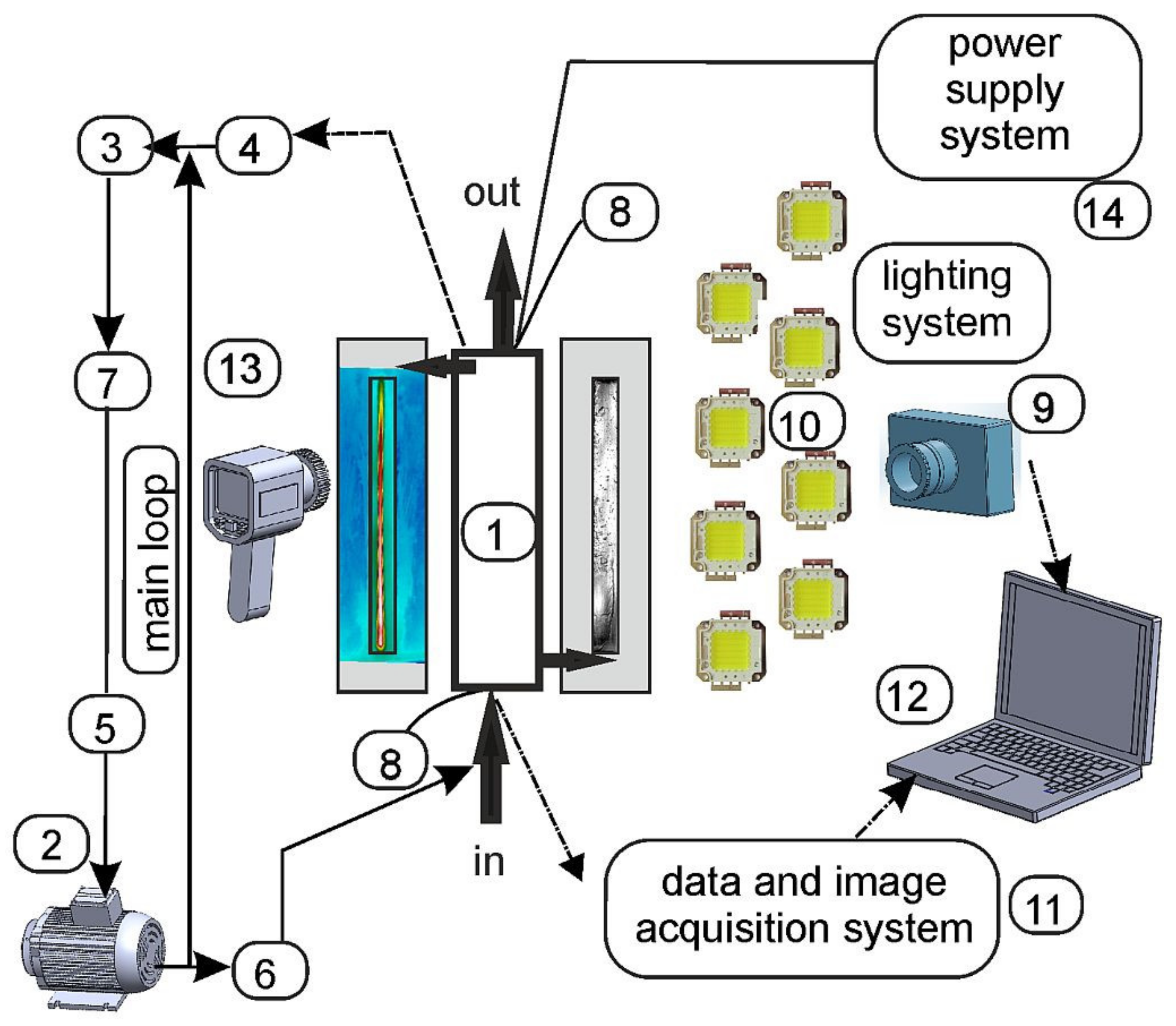
2.1. Main Circuits
2.2. Test Sections
2.3. Experimental Parameters and Accuracies
3. HTC Determination
4. Results and Discussion
4.1. Database of Selected Experiments
4.2. The Results—Analysis and Observations
- With the increase of mass flux, the temperature difference corresponding to ONB increased—see Figure 16a,c.
- The highest temperature difference at ONB was observed for the vertical channel with fluid up-flow (O—90°), in comparison to both horizontal orientations (O—0° and O—180°)—see Figure 16d.
- The highest temperature difference at ONB occurred for HFE 7100 in comparison to other tested fluids—see Figure 16e.
- The lowest temperature difference at ONB was gained for electroerosion and vibration-assisted laser No. 2 surface texturing, and the highest one for porous surfaces produced by soldering iron powder—see Figure 16f.
5. Conclusions
- Inlet pressure (subcooled boiling region):
- ∘
- Higher HPT was achieved at higher pin, and higher HTC at lower pin (180 mm long channel).
- Mass flux (subcooled boiling region):
- ∘
- Higher HPT was reached for lower G (both test sections), the highest HTC was obtained for the lowest G at the highest qw (180 mm long channel), and for the higher G at lower qw (32 mm long channel), and larger bubbles were observed near channel side walls for the lowest G.
- Spatial orientation of a mini-channel (subcooled boiling region):
- ∘
- The highest HPT was noticed for the lowest G and at O—270°, for lower qw. The highest HTC was achieved for higher G and all qw, for O—270°, and more gaseous phase with locally elongated agglomerates was observed for O—270° (180 mm long channel).
- ∘
- The highest HPT was detected for all qw, the highest HTC was obtained for the highest qw and the lowest and the least fragmented bubbles (32 mm long channel) for O—0°.
- Working fluids:
- ∘
- The highest HTC was achieved for HFE-7000 for all qw, at the subcooled boiling region, and for FC-72 and HFE-7000, for all qw, at the saturated boiling region. More developed vapor structures as elongated agglomerates were observed for FC-72 in comparison to other refrigerants, and for HFE-7000, bubbly, bubbly-slug and slug structures were recorded.
- Heated plate surface of a mini-channel:
- ∘
- The highest HTC was obtained for electroerosion and vibration-assisted laser No. 2 surface texturing at both boiling regions. The highest vapor share in two-phase flow structures with elongated agglomerates in comparison to other tested plate surfaces was observed for electroerosion surface texturing, and bubbles of larger sizes and elongated agglomerates were recorded for vibration-assisted laser No. 2 surface texturing.
Author Contributions
Funding
Data Availability Statement
Acknowledgments
Conflicts of Interest
Nomenclature
| A | area of the heated plate, m2 |
| f | fluid |
| G | mass flux, kg/(m2·s) |
| HPT | heated plate temperature, K |
| HTC | heat transfer coefficient, W/(m2·K) |
| I | current, A |
| L | length of the mini-channel, m |
| O | channel orientation |
| ONB | onset of nucleate boiling |
| pin | pressure at the mini-channel inlet, Pa |
| qw | heat flux density, W/m2 |
| Ra | arithmetic mean deviation of the roughness profile of the plate surface, μm |
| S | heated plate surface |
| T | temperature, K |
| the 1st | the test section with a singular mini-channel of LIRT = 180 mm |
| the 2nd | the test section with five parallel mini-channels of LIRT = 32 mm |
| x | direction perpendicular to the fluid flow direction and the channel width, m |
| Greek symbols | |
| δ | depth, thickness, m |
| ∆U | voltage drop, V |
| λ | thermal conductivity, W/(m·K) |
| Subscripts | |
| f | fluid |
| IRT | infrared thermography |
| l | liquid |
| P | plate |
| sat | saturated |
References
- Kanizawa, F.T.; Tibiriçá, C.B.; Ribatski, G. Heat transfer during convective boiling inside microchannels. Int. J. Heat Mass Transf. 2016, 93, 566–583. [Google Scholar] [CrossRef]
- Sun, Z.-C.; Ma, X.; Ma, L.-X.; Li, W.; Kukulka, D. Flow Boiling Heat Transfer Characteristics in Horizontal, Three-Dimensional Enhanced Tubes. Energies 2019, 12, 927. [Google Scholar] [CrossRef] [Green Version]
- Jige, D.; Inoue, N. Boiling heat transfer, pressure drop, and flow pattern in a horizontal square minichannel. Int. J. Heat Fluid Flow 2019, 78, 108433. [Google Scholar] [CrossRef]
- See, Y.S.; Leong, K.C. Entropy generation for flow boiling on a single semi-circular minichannel. Int. J. Heat Mass Transf. 2020, 154, 119689. [Google Scholar] [CrossRef]
- He, B.; Luo, X.; Yu, F.; Zhou, J.; Zhang, J. Flow boiling characteristics in bi-porous minichannel heat sink sintered with copper woven tape. Int. J. Heat Mass Transf. 2020, 158, 119988. [Google Scholar] [CrossRef]
- Klugmann, M.; Dąbrowski, P.; Mikielewicz, D. Flow distribution and heat transfer in minigap and minichannel heat exchangers during flow boiling. Appl. Therm. Eng. 2020, 181, 116034. [Google Scholar] [CrossRef]
- Cheng, X.; Yao, Y.; Wu, H. An experimental investigation of flow boiling characteristics in silicon-based groove-wall microchannels with different structural parameters. Int. J. Heat Mass Transf. 2021, 168, 120843. [Google Scholar] [CrossRef]
- Enoki, K.; Ono, M.; Okawa, T.; Kristiawan, B.; Wijayanta, A.T. Water flow boiling heat transfer in vertical minichannel. Exp. Therm. Fluid Sci. 2020, 117, 110147. [Google Scholar] [CrossRef]
- Markal, B.; Candan, A.; Aydin, O.; Avci, M. Experimental investigation of flow boiling in single minichannels with low mass velocities. Int. Commun. Heat Mass Transf. 2018, 98, 22–30. [Google Scholar] [CrossRef]
- Gasanov, B.M. Flow boiling of water and emulsions with a low-boiling disperse phase in minichannels. Int. J. Heat Mass Transf. 2018, 126, 9–14. [Google Scholar] [CrossRef]
- Orman, Ł.J.; Radek, N.; Pietraszek, J.; Szczepaniak, M. Analysis of enhanced pool boiling heat transfer on laser-textured surfaces. Energies 2020, 13, 2700. [Google Scholar] [CrossRef]
- Dąbek, L.; Kapjor, A.; Orman, Ł.J. Distilled water and ethyl alcohol boiling heat transfer on selected meshed surfaces. Mech. Ind. 2019, 20, 701. [Google Scholar] [CrossRef]
- Wojtasik, K.; Rullière, R.; Krolicki, Z.; Zajaczkowski, B.; Bonjour, J. Subcooled boiling regime map for water at low saturation temperature and subatmospheric pressure. Exp. Therm. Fluid Sci. 2020, 118, 110150. [Google Scholar] [CrossRef]
- Hożejowska, S.; Kaniowski, R.; Pastuszko, R. Application of the Trefftz Method for Pool Boiling Heat Transfer on Open Microchannel Surfaces. Heat Transf. Eng. 2021, 1–13. [Google Scholar] [CrossRef]
- Pastuszko, R.; Kaniowski, R.; Wójcik, T.M. Comparison of pool boiling performance for plain micro-fins and micro-fins with a porous layer. Appl. Therm. Eng. 2020, 166, 114658. [Google Scholar] [CrossRef]
- Kaniowski, R.; Pastuszko, R. Pool Boiling of Water on Surfaces with Open Microchannels. Energies 2021, 14, 3062. [Google Scholar] [CrossRef]
- Bohdal, T.; Kruzel, M. Refrigerant condensation in vertical pipe minichannels under various heat flux density level. Int. J. Heat Mass Transf. 2020, 146, 118849. [Google Scholar] [CrossRef]
- Kruzel, M.; Bohdal, T.; Sikora, M. Heat transfer and pressure drop during refrigerants condensation in compact heat exchangers. Int. J. Heat Mass Transf. 2020, 161, 120283. [Google Scholar] [CrossRef]
- Strąk, K.; Piasecka, M.; Maciejewska, B. Spatial orientation as a factor in flow boiling heat transfer of cooling liquids in enhanced surface minichannels. Int. J. Heat Mass Transf. 2018, 117, 375–387. [Google Scholar] [CrossRef]
- Strąk, K.; Piasecka, M. The applicability of heat transfer correlations to flows in minichannels and new correlation for subcooled flow boiling. Int. J. Heat Mass Transf. 2020, 158, 119933. [Google Scholar] [CrossRef]
- Piasecka, M.; Strąk, K.; Maciejewska, B. Heat transfer characteristics during flow along horizontal and vertical minichannels. Int. J. Multiph. Flow 2021, 137, 103559. [Google Scholar] [CrossRef]
- Piasecka, M.; Strąk, K. Influence of the Surface Enhancement on the Flow Boiling Heat Transfer in a Minichannel. Heat Transf. Eng. 2019, 40, 1162–1175. [Google Scholar] [CrossRef]
- Depczyński, W.; Piasecki, A.; Piasecka, M.; Strąk, K. Impact of Fe powder sintering and soldering in production of porous heating surface on flow boiling heat transfer in minichannels. E3S Web Conf. 2017, 19, 03012. [Google Scholar] [CrossRef] [Green Version]
- Maciąg, A.; Grysa, K. Trefftz Method of Solving a 1D Coupled Thermoelasticity Problem for One- and Two-Layered Media. Energies 2021, 14, 3637. [Google Scholar] [CrossRef]
- Blasiak, S. Influence of Thermoelastic Phenomena on the Energy Conservation in Non-Contacting Face Seals. Energies 2020, 13, 5283. [Google Scholar] [CrossRef]
- Piasecka, M.; Maciejewska, B.; Łabędzki, P. Heat Transfer Coefficient Determination during FC-72 Flow in a Minichannel Heat Sink Using the Trefftz Functions and ADINA Software. Energies 2020, 13, 6647. [Google Scholar] [CrossRef]
- Piasecka, M.; Hożejowska, S.; Maciejewska, B.; Pawińska, A. Time-Dependent Heat Transfer Calculations with Trefftz and Picard Methods for Flow Boiling in a Mini-Channel Heat Sink. Energies 2021, 14, 1832. [Google Scholar] [CrossRef]
- Michalski, D.; Strąk, K.; Piasecka, M. Estimating uncertainty of temperature measurements for studies of flow boiling heat transfer in minichannels. EPJ Web Conf. 2019, 213, 02059. [Google Scholar] [CrossRef]
- Maciejewska, B.; Łabędzki, P.; Piasecki, A.; Piasecka, M. Comparison of FEM calculated heat transfer coefficient in a minichannel using two approaches: Trefftz base functions and ADINA software. EPJ Web Conf. 2017, 143, 02070. [Google Scholar] [CrossRef] [Green Version]
- Piasecka, M.; Strąk, K.; Maciejewska, B. Calculations of Flow Boiling Heat Transfer in a Minichannel Based on Liquid Crystal and Infrared Thermography Data. Heat Transf. Eng. 2017, 38, 332–346. [Google Scholar] [CrossRef]
- Strąk, K.; Piasecka, M. Research on flow boiling heat transfer for vertical upward and downward flows along a minichannel with a smooth heated surface. E3S Web Conf. 2018, 70, 02014. [Google Scholar] [CrossRef]
- Strąk, K.; Piasecka, M.; Strąk, D. Enhanced Surfaces Used in Research on Flow Boiling Heat Transfer in Minichannels. Mater. Res. Proc. 2018, 5, 154–159. [Google Scholar]


| Geometrical Characteristics of Mini-Channels | Test Section | |
|---|---|---|
| the 1st | the 2nd | |
| Number of mini-channels | 1 | 5 |
| Length of a mini-channel, mm | 180 | 32 |
| Width of a mini-channel, mm | 16 | 6 |
| Depth of a mini-channel, mm | 1.7 | 1 |
| Features of Experiments | Specific Data |
|---|---|
| Mass flux, G | 89 ÷ 616 (kg/(m2∙s)) |
| Inlet pressure, pin | 110 ÷ 370 (kPa) |
| Inlet liquid subcooling | 35 ÷ 58 (K) |
| Heat flux (density), qw | 2.5 ÷ 102 (kW/m2) |
| Spatial orientation of the test section | 0°, 90°, 180°, 270° |
| Refrigerant | FC-72, HFE-649, HFE-7000, HFE-7100 |
| Modified heated wall surface produced by: |
|
| Boiling region | subcooled/saturated |
| Experimental Parameter | Absolute Error | More Specific Data |
|---|---|---|
| Mass flow rate | 1.67 ×∙10−5 (kg/s) | maximum error of reading |
| Absolute Pressure | 1 285 (Pa) | absolute error of the measurement |
| Temperature of the heated plate, Tp | 1 (K) | absolute error of the measurement (IRT) |
| Temperature of the fluid, Tf, at the inlet/outlet | 0.34 (K) | absolute error of the measurement [21] |
| Refrigerant | Boiling Point Temperature (K) | Density (kg/m3) | Kinematic Viscosity (m2/s) | Vapor Pressure (Pa) | Heat of Evaporation (J/kg) |
|---|---|---|---|---|---|
| FC-72 | 329 | 1680 | 0.38 ×∙10−6 | 30∙103 | 88 ×∙103 |
| HFE-649 | 322 | 1600 | 0.40 ×∙10−6 | 40∙103 | 88 ×∙103 |
| HFE-7000 | 307 | 1400 | 0.32 ×∙10−6 | 65∙103 | 142 ×∙103 |
| HFE-7100 | 334 | 1510 | 0.38 ×∙10−6 | 27∙103 | 112 ×∙103 |
| No. | Tested Factor (Figure) | Boiling Region | Channel Length, LIRT, Heated Plate Surface, S | Fluid, f | Spatial Orientation of Mini-Channels, O | Heat Flux, qw (kW/m2) | Mass Flux, G (kg/(m2s)) | Inlet Pressure, pin (kPa) | Inlet Liquid Subcooling (K) |
|---|---|---|---|---|---|---|---|---|---|
| #1 | Inlet pressure (Figure 5) | subcooled | 180 mm, v.a. las. 2 | HFE-649 | 90° | 50 57 67 | 400 | 160, 257, 165, 322, 215, 370 | 53 |
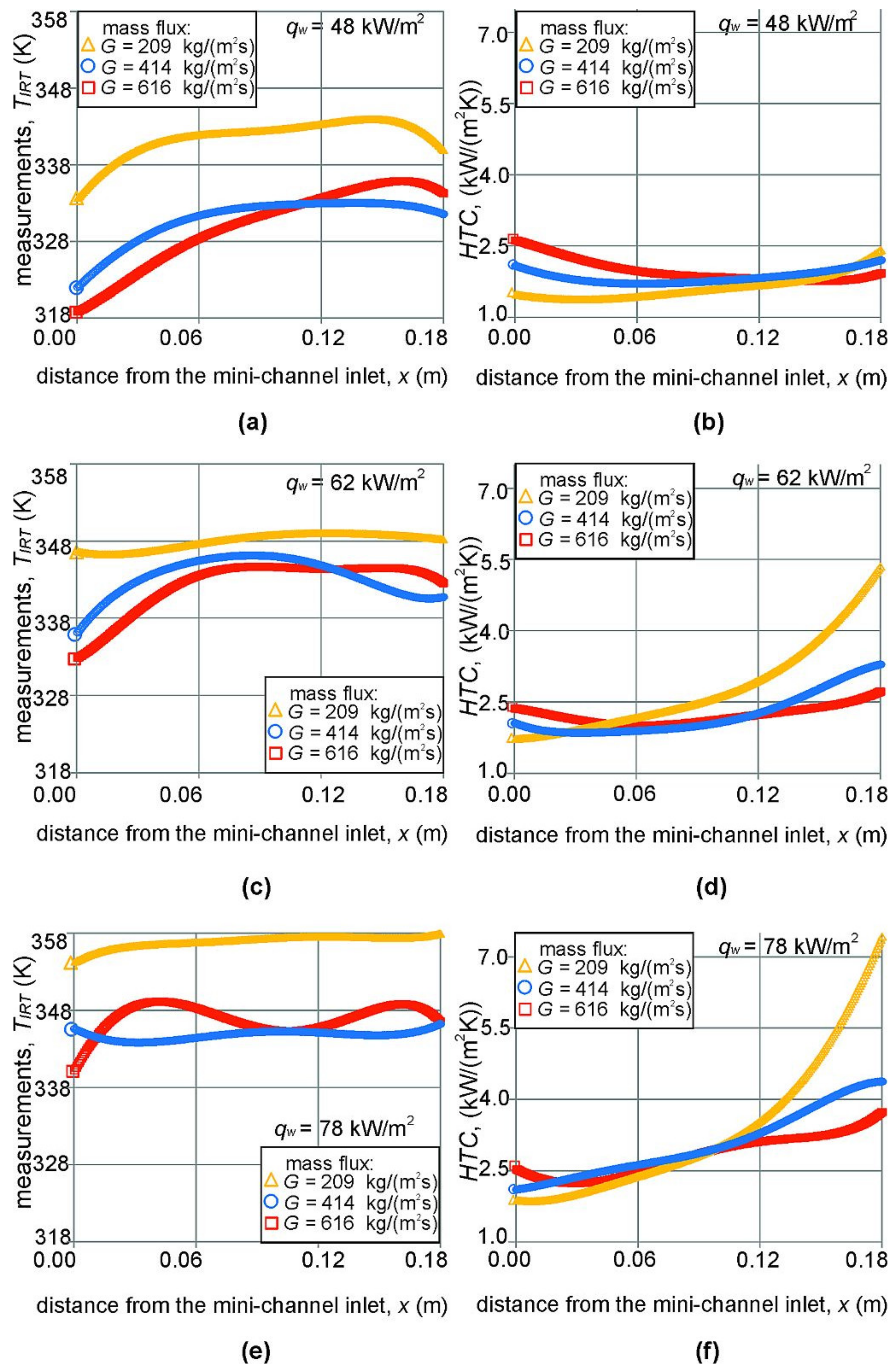
| #2 | Mass flux (Figure 6) | subcooled | 180 mm, smooth | FC-72 | 90° | 48, 62, 78 | 209, 414, 616 | 160 | 58 |
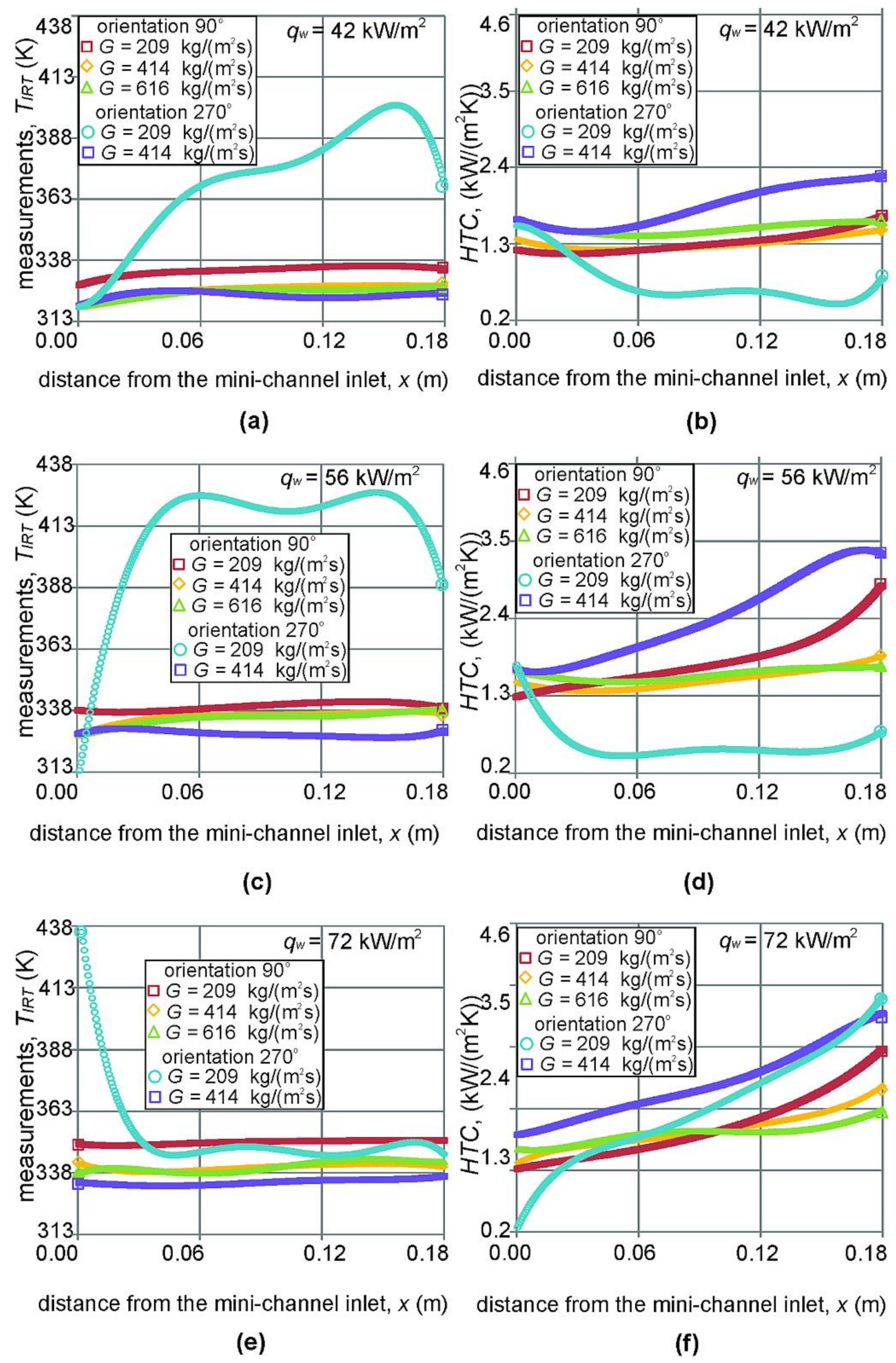
| #3 | Mass flux, channel orientation (Figure 7) | subcooled | 180 mm, smooth | HFE-649 | 90°, 270° | 42, 56, 72 | 209, 414, 616 | 170 | 48 |
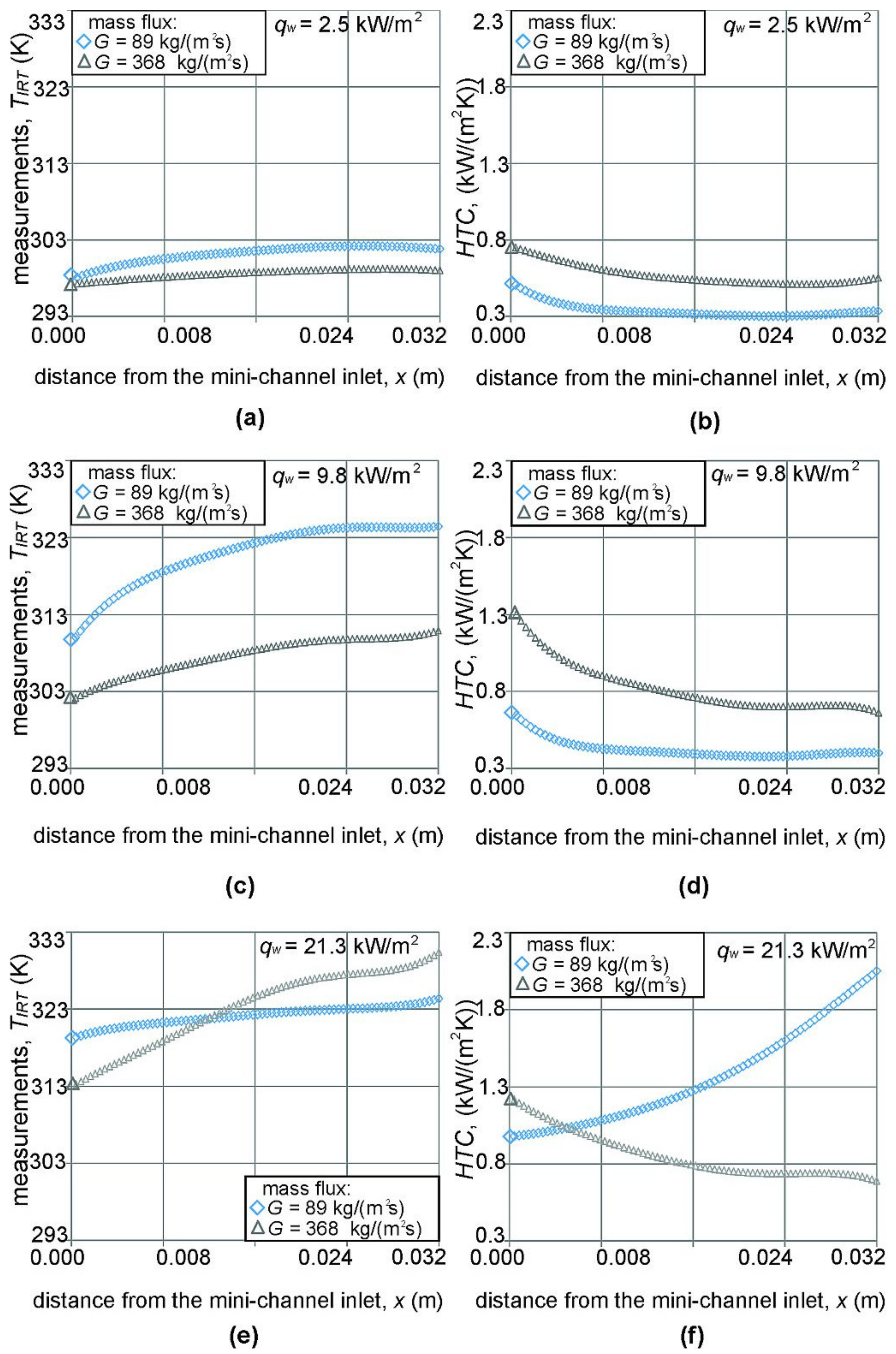
| #4 | Mass flux (Figure 8) | subcooled | 32 mm, smooth | FC-72 | 90° | 2.5, 9.8, 21.3 | 89, 368 | 111 | 38 |
| #5 | Channel orientation (Figure 9) | subcooled | 32 mm, smooth | FC-72 | 0° 90° 180° | 2.5, 9.8, 21.3 | 440 | 110 | 35 |
| #6 | Working fluid (Figure 10a,b) | subcooled | 180 mm, v.a. las. 2 | FC-72 HFE-649 HFE-7000 HFE-7100 | 90° | 55, 81 | 423 | 170 | 39 |
| #7 | Working fluid (Figure 10c,d) | saturated | 180 mm, v.a. las. 2 | FC-72 HFE-7000 HFE-7100 | 90° | 91, 102 | 428 | 200 | 41 |
| #8 | Heated plate surface (Figure 11a,b) | subcooled | 180 mm, v.a. las. 2 | FC-72 | 90° | 47, 73 | 356 | 121 | 42 |
| #9 | Heated plate surface (Figure 11c,d) | saturated | 180 mm, smooth, v.a. las. 1,2,3, electr., sold. and sin. i.p. | FC-72 | 90° | 84, 93 | 349 | 140 | 43 |
| Tested Factor | Main Experimental Data | HPT | HTC | Flow Structures |
|---|---|---|---|---|
| Inlet pressure (pin) | LIRT = 180 mm S—v.a. las. 2 f—HFE-649 O—90° | Figure 5a,c,e
| Figure 5b,d,f (subcooled boiling region)
| Remarks based on experiments
|
| Mass flux (G) | LIRT = 180 mm S—smooth f—FC-72 f—HFE-649 O—90° | Figure 6a,c,e (FC-72)
| Figure 6b,d,f (subcooled boiling region, FC-72) | Figure 12a,b (HFE-649)
|
| Mass flux (G) orientation (O) | LIRT = 180 mm S—smooth f—HFE-649 O—90°, 270° | Figure 7a,c,e
| Figure 7b,d,f (subcooled boiling region)
| Figure 12a–d
|
| Mass flux (G) | LIRT = 32 mm S—smooth f—FC-72 O—90° | Figure 8a,c,e
| Figure 8b,d,f (subcooled boiling region) | Figure 13b,d |
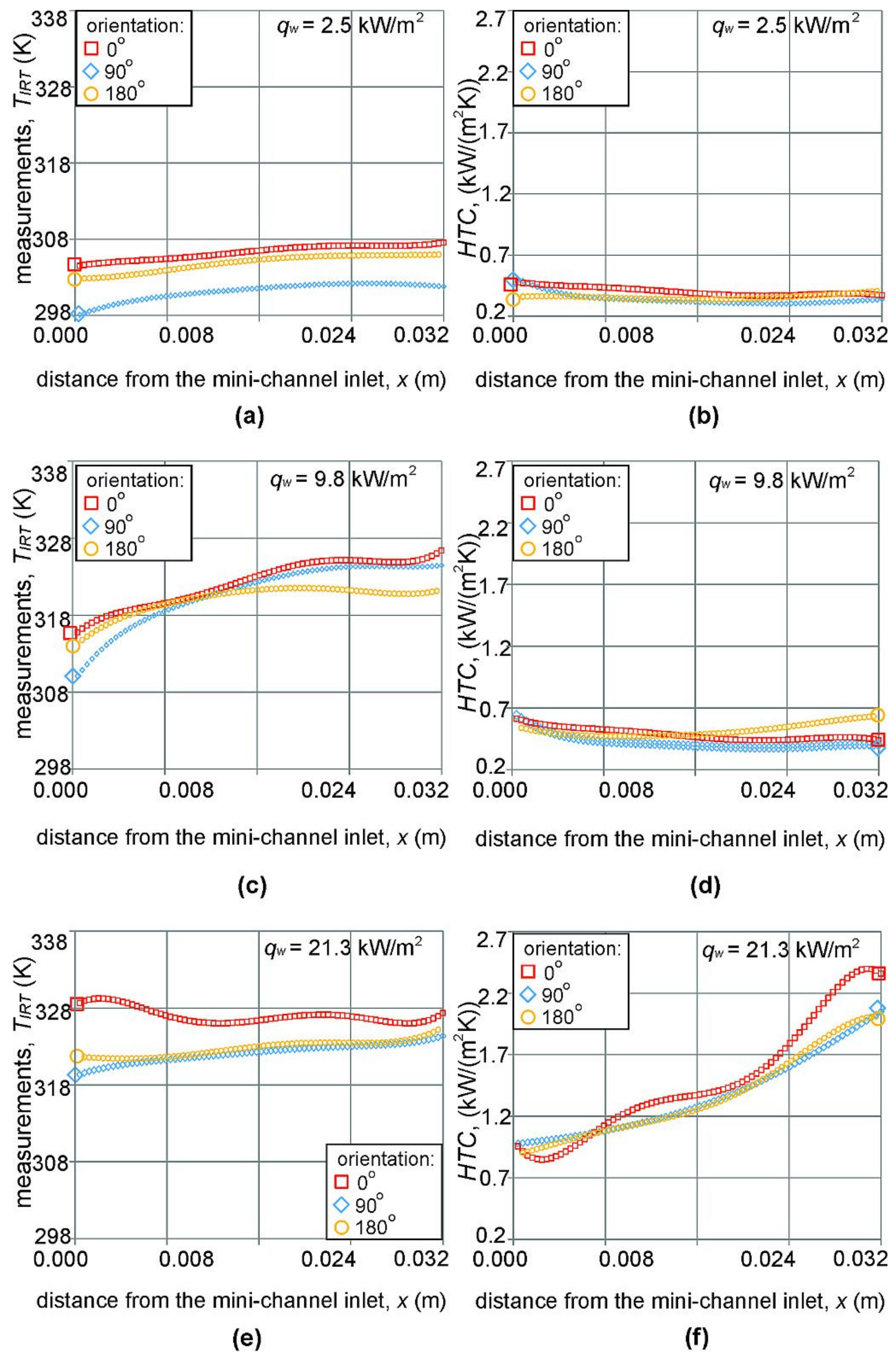
| Orientation (O) | LIRT = 32 mm S—smooth f—FC-72 O—0°, 90°, 180° | Figure 9a,c,e
| Figure 9b,d,f (subcooled boiling region) | Figure 13a,b,c |
| Fluid (f) | LIRT = 180 mm S—v.a. las. 2 f—FC-72 HFE-649 HFE-7000 HFE-7100 O—90° | — | Figure 10a,b (subcooled boiling region)
| Figure 14a–d
|
| Fluid (f) | LIRT = 180 mm S—v.a. las. 2 f—FC-72 HFE-7000, HFE-7100 O—90° | — | Figure 10c,d (saturated boiling region) | Figure 14a–d
The least numerous bubbles observed for the HFE-649 (Figure 14b) |
| Heated plate surface (S) | LIRT = 180 mm S—smooth v.a. las. 1,2,3, electr., sold. and sin. i.p. f—FC-72 O—90° | — | Figure 11a,b (subcooled boiling region)
| Figure 15a–d
|
| Heated plate surface (S) | LIRT = 180 mm S—smooth v.a. las. 1,2,3, electr., sold. and sin. i.p. f—FC-72 O—90° | — | Figure 11c,d (saturated boiling region)
|
Publisher’s Note: MDPI stays neutral with regard to jurisdictional claims in published maps and institutional affiliations. |
© 2021 by the authors. Licensee MDPI, Basel, Switzerland. This article is an open access article distributed under the terms and conditions of the Creative Commons Attribution (CC BY) license (https://creativecommons.org/licenses/by/4.0/).
Share and Cite
Piasecka, M.; Strąk, K. Characteristics of Refrigerant Boiling Heat Transfer in Rectangular Mini-Channels during Various Flow Orientations. Energies 2021, 14, 4891. https://doi.org/10.3390/en14164891
Piasecka M, Strąk K. Characteristics of Refrigerant Boiling Heat Transfer in Rectangular Mini-Channels during Various Flow Orientations. Energies. 2021; 14(16):4891. https://doi.org/10.3390/en14164891
Chicago/Turabian StylePiasecka, Magdalena, and Kinga Strąk. 2021. "Characteristics of Refrigerant Boiling Heat Transfer in Rectangular Mini-Channels during Various Flow Orientations" Energies 14, no. 16: 4891. https://doi.org/10.3390/en14164891
APA StylePiasecka, M., & Strąk, K. (2021). Characteristics of Refrigerant Boiling Heat Transfer in Rectangular Mini-Channels during Various Flow Orientations. Energies, 14(16), 4891. https://doi.org/10.3390/en14164891