Article

Analytical Design of Sculpted Rotor Interior Permanent Magnet Machines

1
Department of Mechanical Engineering, Michigan State University, East Lansing, MI 48824, USA
2
Department of Electrical and Computer Engineering, Michigan State University, East Lansing, MI 48824, USA
*
Author to whom correspondence should be addressed.
Energies 2021, 14(16), 5109; https://doi.org/10.3390/en14165109
Submission received: 30 June 2021 / Revised: 16 August 2021 / Accepted: 17 August 2021 / Published: 19 August 2021
(This article belongs to the Special Issue Advances in the Field of Electrical Machines and Drives)

Abstract

:
A computationally efficient design of interior permanent magnet (IPM) motor rotor features is investigated utilizing analytical methods. Over the broad operating range of IPM machines, interactions of MMF sources, permeances, and currents result in torque harmonics. The placement of traditional rotor features along with sculpt features are utilized to minimize torque ripple and maximize average torque. We extend the winding function theory to include the IPM rotor’s primary and secondary reluctance paths and the non-homogeneous airgap of the rotor sculpt features. A new analytical winding function model of the single-V IPM machine is introduced, which considers the sculpted rotor and how this model can be used in the design approach of machines. Results are validated with finite elements. Rotor feature trends are established and utilized to increase design intuition and reduce dependency upon the lengthy design of experiment optimization processes.

1. Introduction

The IPM motor is increasingly being utilized throughout industry as a primary source of propulsion due to its good efficiency, torque and power density. Examples include the development of battery electric vehicle traction motors [1,2], plugin hybrid electric vehicles [3], and hybrid electric vehicles [4]. Ideally, the traction machine provides an average torque produced from a sinusoidal distribution of the airgap flux density. In reality, embedding the magnet within the salient structure of the rotor lamination and distributing windings in discrete locations result in airgap flux density harmonics. These harmonics result in increased torque ripple, radial forces, losses, and other unwanted phenomena.
In this paper, an approach to minimize torque ripple with rotor features is presented, based upon analytically modeling the machine features. The analytical modeling approach enables efficient use of computational resources, without the sacrifice of harmonic content, prior to the use of more expensive finite element methods. The calculation of the IPM machines’ spatially-dependent torque harmonics is performed through the extension of the winding function method. New to the winding function framework is a method to model the equipotential nature of the rotor’s salient features and rotor surface modifications. The non-homogeneous airgap of rotor surface modifications is included in the model through an additional MMF term. Unique to this analytical method, both the constituents and aggregates of the torque harmonics are found. A detailed investigation into the rotor geometry design space to minimize torque harmonics while managing average torque design trade-off is presented.
Inherent to the design of IPM machines, torque ripple is a persistent problem. Design choices to increase torque density or decrease manufacturing cost are often at odds with minimizing the torque ripple [5]. Rotor features, including surface modifications or sculpt features, are utilized to minimize the torque harmonics. The ability to reduce ripple by design must consider the speed, current, and control angle ranges of the IPM machine.
Analytical expressions for the airgap and torque harmonics are developed for the IPM in [6,7]. The synchronous reluctance of torque harmonics presented in [8] is extended to the IPM machine in [7]. The expressions are useful in setting the stator slot and rotor barrier counts but do not model the machine.
Analytical models better relate the physical geometry of the machine to its airgap and flux density harmonics. Directly solving the Laplacian–Poisson is difficult [9,10]. Subdomain models break the model into pieces in which the Laplacian–Poisson can be more readily solved [11,12]. Magnetically Equivalent Circuits (MEC) divide the geometry into smaller manageable pieces [13]. Methods depending on winding functions allow for the geometry and harmonics to be described, but the second reluctance path can be difficult to model. The airgap harmonics of the salient pole permanent magnet synchronous machine are presented in [14] but does not address torque ripple or the secondary reluctance path of the IPM machine. The rotor permeance path is approximated in [15] to determine the torque ripple of the machine under study, but does not fully describe an IPM machine. The double V shaped IPM is presented in [16], in which flux densities are calculated through an MEC model and described with a Fourier series. The single V IPM presented in [17] considers the pole cap effect but does not consider torque ripple harmonics. The single V, delta and double V IPM rotor configurations are shown in Figure 1. Moreover, the airgap harmonics in permanent magnet synchronous machines were calculated in [18,19], but the effect of the second reluctance path on the airgap harmonics was not included in the calculations.
Recently, researchers have investigated rotor modifications to alter the airgap, modify airgap flux, and improve torque harmonics. The first feature type is pole shaping, which creates a small airgap near the d-axis and an increased airgap in the region of the q-axis. The torque ripple was reduced for the single magnet flat magnet IPM and optimized with a differential evolution algorithm and finite elements [20]. A surface-mount PM pole-shaped machine was studied with an analytical solution to the field in [21]. The 2D solution was confirmed both by finite element and testing. The pole-shaped single flat magnet IPM was optimized with a response surface method within FE [22]. This included the use of rotor core modifications as well; both FE and experimental results were presented. The flat magnet IPM pole shape was optimized, along with the creation of design rules for the ratio of q-axis and d-axis airgap length in [23]. The single V magnet-shape IPM was improved with pole shaping using finite elements in [24]. Cogging torque and back emf were measured. A third harmonic was added to the pole shape in [25], which studied the machine in finite elements. A second feature type is in the rotor core, which creates a small hole in the rotor core near the airgap in order to redirect flux. Holes in the rotor core’s second reluctance path of the single magnet IPM were shown to decrease torque ripple using finite elements in [26]. The double V magnet IPM machine with improved torque ripple, due to holes in rotor iron core and rotor surface sculpt features, was shown to improve torque ripple but lower average torque in [27]. The delta magnet IPM shape included modified internal rotor features to improve for average torque and decrease iron loss in [28].
The third and final feature type is sculpting the rotor surface at the airgap to redirect flux. The single flat magnet IPM machine cogging torque was reduced in [29] and experimentally verified. A grid on/off optimization of the rotor surface was conducted on the single flat magnet IPM using finite elements in [30,31], resulting in an asymmetric rotor surface with reduction in torque ripple and maintaining average torque. The double V-magnet IPM torque ripple was minimized with both rotor core and surface sculpted features in [27]. The delta-magnet IPM machine torque ripple was minimized with rotor surface sculpt features in [32]. Then, a general analytical expression for torque harmonics was developed and utilized to optimize the solution with finite elements.
This paper presents a detailed analytical model of the sculpted rotor IPM machine. The model allows for a break down of flux and torque into magnet, primary reluctance, secondary reluctance, and sculpt features. Multiple sculpt features configurations are demonstrated to achieve similar torque harmonic reductions. Results are validated with finite elements and utilized to improve the torque harmonic characteristics of an existing industrialized machine. This is because finite elements accurately predict experimental results across a broad range of machines [33,34,35,36] and have been utilized to evaluate and compare machine types [37,38,39] and validate analytical solutions [40,41,42,43,44,45,46,47,48,49,50]. Section 2 introduces the topics relevant to the design of IPM motor construction and control. Section 3 provides details on how to model an IPM motor magneto motive force (MMF), permeance, and linear current density in order to model the machine geometry, flux, and torque harmonics. The model developed in Section 3 is applied to that of a well-known industrial IPM machine in Section 4. Design features are explored in Section 5. Contributions of this paper include a novel analytical winding function-based IPMSM model, the analytical description of rotor sculpt features, and modeling of magnet and reluctance torque component alignment due to asymmetric sculpt features. In addition, this paper demonstrates the torque effects of reluctance path pole arc, sculpt feature type (symmetrical/asymmetrical), sculpt feature location, and sculpt feature depth and sculpt feature width.

2. Flux Distribution and Control of IPM Machines

Performance, harmonics, and control are all dependent upon the distribution of flux density within the machine. Permanent magnets provide a constant source of flux density, which enable efficient torque production but can limit high speed operation. Reluctance features provide a source of torque dependent upon armature current at high current angles, useful for extending operation at high speeds. The ratio of magnet and reluctance torque is balanced to enable the machine to stay within its operation constraints while efficiently using the voltage and current available at the terminals. This section provides a brief overview of the machine’s construction, design features, and flux paths. In addition, the necessary framework for control is introduced.

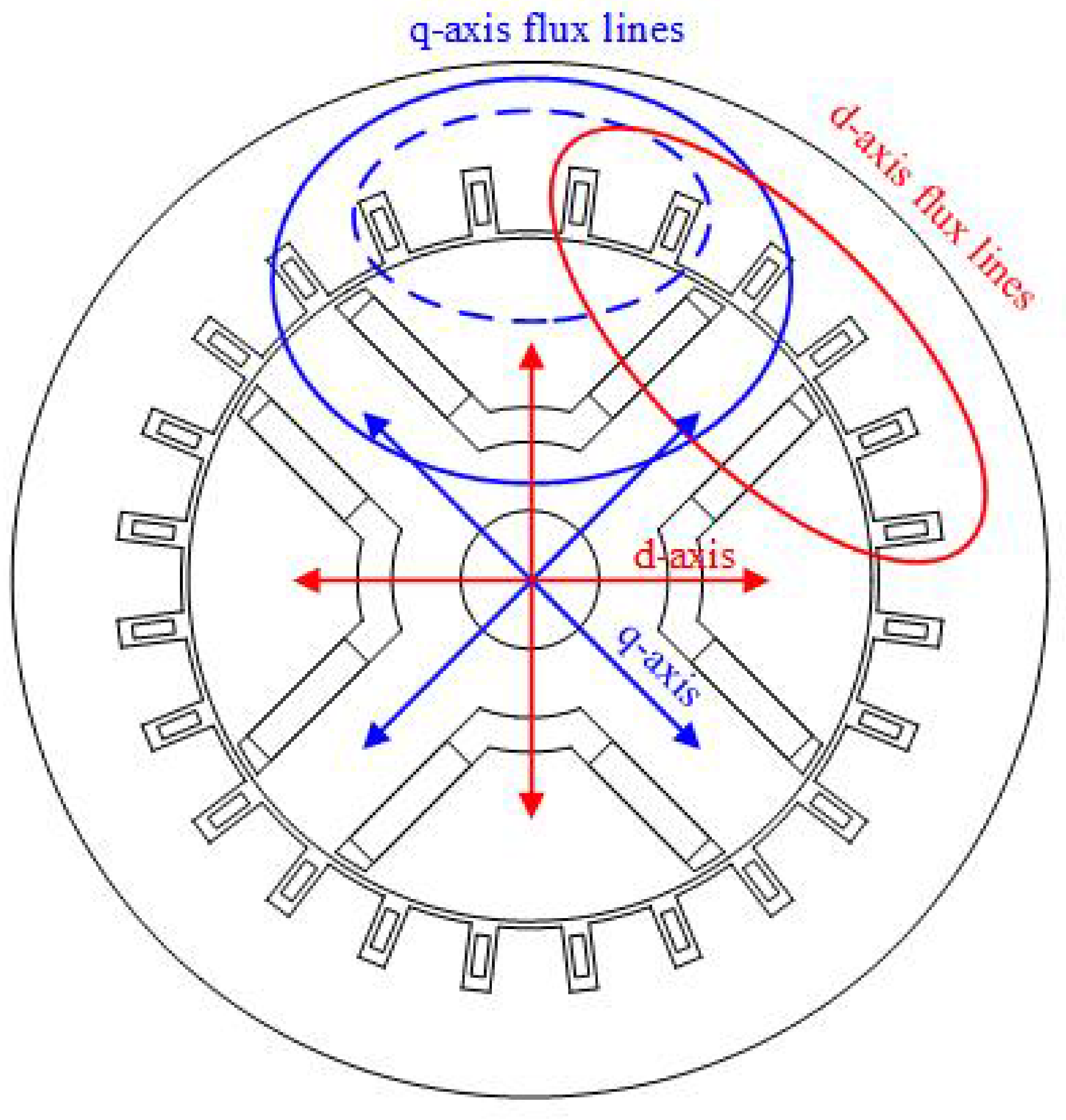
2.1. Flux Distribution

Figure 2 shows a two-dimensional illustration of a four pole IPM machine. The IPM motor is fundamentally constructed of a stator and a rotor. The stator is the mechanically grounded part of the machine. It is constructed of slots, teeth, a yoke, and the three phase windings. The stator teeth and yoke are constructed of a magnetically permeable iron alloy. The teeth and yoke allow for easy flow of magnetic flux to and from the airgap of the machine. The slots allow space for the copper windings. The windings are distributed within the slots to produce a current dependant magneto motive force (MMF), which in turn creates the radial magnetic flux density. The placement of the windings also creates a current density along the bore of the stator, resulting in a tangential component of flux density. When arranged and controlled properly, the currents in the windings produce a rotating set of fields to produce torque.
The rotor, the mechanically rotating part, is constructed of iron ribs, air-filled barriers, iron bridges, and permanent magnets. The iron core is constructed of ribs and bridges. The ribs control the distribution of flux density while the bridges mechanically couple all parts together. Barriers provide air pockets, which assist the ribs in directing flux, and also contain embedded magnets. The permanent magnets are embedded within the rotor and produce an MMF, which is independent of current.
From the perspective of the rotor, a direct axis (d-) and a quadrature axis (q-) of the machine are electromagnetically aligned to the rotor characteristics. The d- axis is the primary axis of which the permanent magnet flux density flows. The magnet flux density flows through the magnet into the central rib of the magnet pole, into the airgap, through the stator teeth and yoke and returns into the adjacent opposite magnet pole. This permanent magnet flux density path is shown in Figure 2 as a red ellipse. The q- axis is the axis in which the armature-induced flux flows through the rotor. This flux is produced from the armature MMF and the reaction of the rotor/stator permeance. Two armature-induced paths result; one through the primary reluctance path, and a second through the secondary reluctance path. The primary reluctance path flux is shown as the solid blue ellipse, and the second reluctance path flux is shown as the dashed blue ellipse in Figure 2.

2.2. Control of IPM Machine

Control must be considered in the design of the IPM motor. The steady state torque and voltage equations are shown in Equations (1)–(3). These are the fundamental starting points to develop the necessary analysis for the control of electric machines. The equations are based upon d- and q- axis voltages, v d and v q , currents, i d and i q , inductance λ d and λ q , magnet flux linkage, λ m , and phase resistance R s . Magnet offset, δ , as shown in Figure 3, is included to account for magnet alignment relative to the reluctance path, which may be caused by rotor sculpting features [51,52]. Traditional IPM alignment would feature δ = 0 , with the d-axis aligned to the maximum of magnet flux linkage. For purposes of this paper, the q-axis remains aligned to the minimum reluctance of the rotors first reluctance path. By inspection, the resistance or loss terms do not have an effect on the torque and only affect the voltage and electrical power. It may be useful to assume the phase resistance is negligible.
τ = 1 2 3 2 ( l d l q ) i d i q + λ m cos ( δ ) i q sin ( δ ) i d
v d = R s i d + ω l q i q ω λ m sin ( δ )
v q = R s i q + ω l d i d + ω λ m cos ( δ )
Performance assessments require including an analysis of the phase current constraint, I m a x , and phase voltage V m a x . For a wye connected machine, I m a x is equal to the phase current, I s s , and is limited by the power devices of the inverter and the electric machines thermal capability. The voltage limit is the maximum phase voltage that the inverter can apply, limited by the specific pulse width modulation (PWM) technique used. The voltage limit for space vector PWM is V m a x = V d c · M I 2 · 3 and six step PWM is V m a x = V d c · M I · 2 · π . The maximum modulation index is set to M I = 0.95 to account for cable and device voltage drops.

3. Analytical Model: MMF, Permeance, Flux, and Torque

This section develops the necessary analytical winding function model for the IPM machine idealized to focus on the effects of the rotor geometry. Assumptions include closed stator slots and no saturation leading to infinite permeability, leaving the permeability of the airgap assumed to be that of free space μ = 4 π 10 7   H m . Stator conductors are modeled by discrete current sheets along the stator bore inner diameter and phases are assumed to be wye connected.
Focused on the MMF interaction with the second reluctance path, the analytical model describes MMF and permeance functions. These winding function-based MMFs, F x ( θ , ϕ ) , and permeance functions, Λ ( θ , ϕ ) , express the harmonic content of stator and rotor features as Fourier series. Relationships between the rotor spatial coordinate θ and rotor position ϕ and current angle β are included. Flux densities are computed using Equation (4), and contributions of the stator and rotor harmonic interactions to the torque ripple are determined.
B r ( θ , ϕ ) = 2 Λ r ( θ , ϕ ) F r ( θ , ϕ )

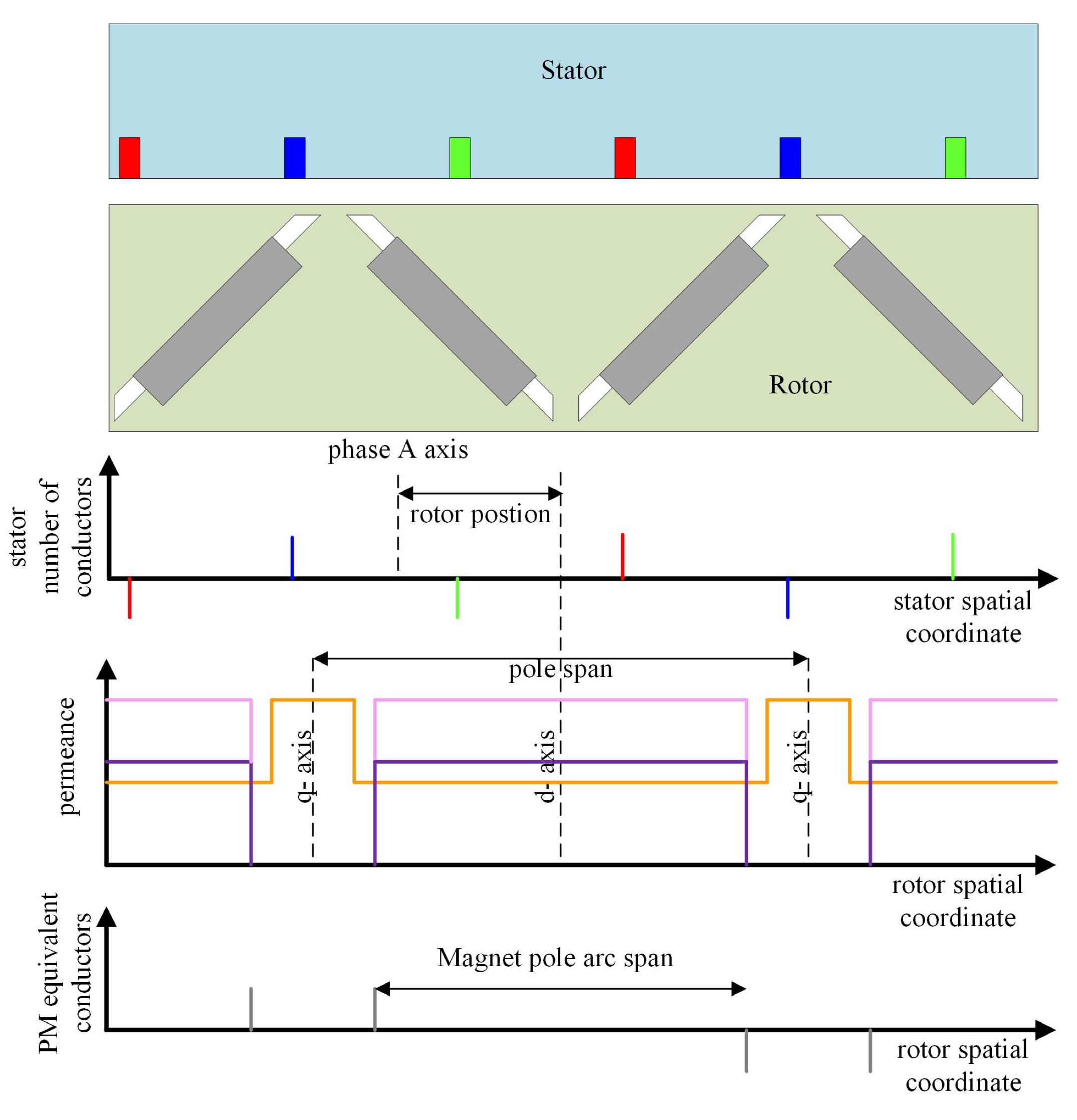
3.1. Permeance Functions

The general form of the permeance functions Λ x , shown in Figure 4, can be written as Equation (5), where the amplitude Y and phase γ define the location of features relative to the d-axis of the machine.
Λ x ( θ ) = n = 0 , 2 , 4 , 6 Y x ( n ) cos ( n θ + γ x ( n ) )
Permeance functions, along with rotor and stator construction, are shown in Figure 4. The salient features of the rotor begin with the definition of the primary reluctance path, which assumes a small airgap l g , aligned with the minimum reluctance of the q-axis, and a large airgap considering barrier and magnet dimensions, l m . Above the magnet, a secondary reluctance path exists, which reacts as equipotential salient iron to the armatures MMF. The permanent magnet permeance path describes the total amount of air the magnet must push its flux through, including its thickness in the same region of the second reluctance path. Coefficients of Equation (5) are derived from the local definition of the permeance Equation (6).
Λ = μ g
The defining airgaps of the permeance functions are listed in Table 1.

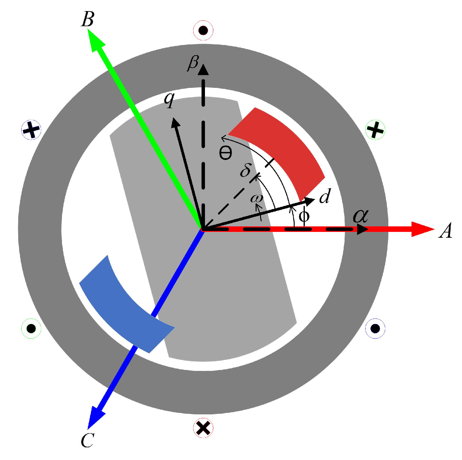
3.2. Magneto Motive Forces (MMF)

Equation (7) gives the general form of the winding function composed of the turns function n ( θ , ϕ ) and its mean < n ( ϕ , θ ) > , where the turns function is a result of the closed path integral of the conductor [53]. MMF functions, F ( θ , ϕ ) , are comprised of the turns function multiplied by a current.
N ( θ , ϕ ) = n ( θ , ϕ ) < n ( ϕ , θ ) >
< n ( θ , ϕ ) > = 1 2 π 0 2 π n ( θ , ϕ ) d θ
Expanded into a Fourier series, the winding takes the form as follows (9):
N x ( θ , ϕ ) = n = 1 , 3 , 5 , 7 Y w f x ( n ) cos ( n θ + γ w f x ( n ) + n ϕ i + n ϕ )
where Y w f x is the coefficient, γ w f x ( n ) is the phase, mechanical order n, rotor position ϕ , and initial rotor position ϕ i .

3.2.1. Stator

Stator MMF is formed from the interaction of the phase currents ( I a , I b , I c ) and the phase winding functions ( N a , N b , N c ). The summation of the three phases creates a rotating MMF, F a b c , which directly acts upon the primary reluctance path.
F a b c ( θ , ϕ ) = N a ( θ , ϕ ) I a ( ϕ , β ) + N b ( θ , ϕ ) I b ( ϕ , β ) + N c ( θ , ϕ ) I c ( ϕ , β )

3.2.2. Magnet

The permanent magnet is represented as an equivalent current I P M , which is related to the remnant flux B r , permeability of free space u , relative permeability μ r , and magnet thickness. Magnet MMF for the IPM machine interacts with the magnet path permeance, where τ m is the magnet’s salient iron pole pitch, and w m is the combined width of the magnets for a single pole.
I P M = B r μ 0 μ r l m
F P M ( θ , ϕ ) = N P M ( θ ) I P M τ m w m

3.2.3. Second Reluctance Path Modification

The equipotential nature of the rotor’s second reluctance path reacts only to the regional harmonics of the stator MMF. In this case, all looping flux that enters the second reluctance path pole arc through the airgap must exit through the same airgap. Modification to the armature MMF by removing its mean satisfies this condition and is made possible through Equation (13). The symbols F < a b c > and < F a b c ( θ , ϕ ) N P M ( θ ) > represent the modified MMF, which interacts with the second reluctance path and the mean of the MMF across this same boundary. As a matter of convenience, the permanent magnet winding function N P M is also used to consider the stator MMF in the region of the second reluctance path, invert it, remove the mean, and revert to the original polarity.
F < a b c > ( θ , ϕ ) = F a b c ( θ , ϕ ) N P M ( θ ) < F a b c ( θ , ϕ ) N P M ( θ ) > N P M ( θ )
< F a b c ( θ , ϕ ) N P M ( θ ) > = 1 2 π 0 2 π F a b c ( θ , ϕ ) N P M ( θ ) d θ 1 2 π 0 2 π N P M ( θ ) d θ

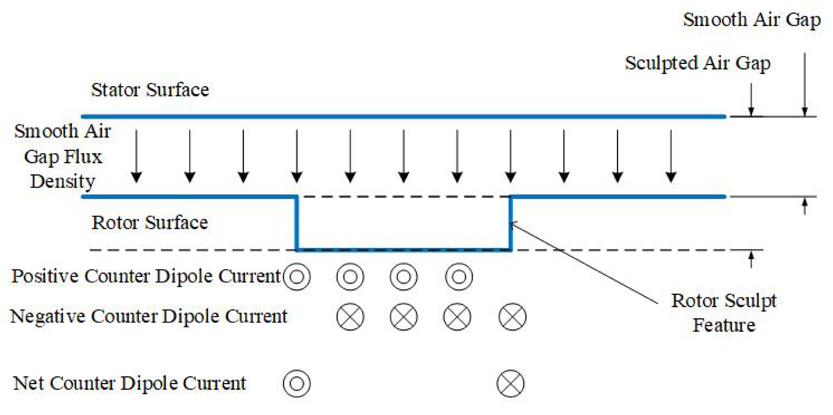
3.3. Sculpt Feature Description: Equivalent Magnetizing Dipole Current

MMF-permeance methods allow for flux density for the IPM smooth rotor homogeneous airgap to be calculated. Rotor sculpting affects both magnet flux distribution and reluctance flux distribution. This smooth rotor MMF-permeance theory does not adequately describe stator slots and rotor sculpt features as it has been developed with a constant airgap dimension [53]. In this section, an extension of winding function theory is developed, which can be used in the description of both slots and sculpts based upon equivalent magnetic currents (EMC) [54] and the equivalent magnetic dipole [55]. These non-homogeneous airgap features are represented by additional MMF terms utilizing the description of a magnetic dipole and its equivalent magnetic currents. The redistribution of flux density and MMF is possible with the use of the equivalent dipole concept.
The magnetic dipole in free space is formed by a loop of radius b and current of I. The solution at far fields, when R > > b , solved in spherical coordinates, using the magnetic vector potential, A , is shown in Equation (15), where the magnetic dipole moment m is written as m = a z I π b 2 [55].
A = μ 0 m × a R 4 π R 2
This dipole in free space can be used to explain the magnetism at the atomistic level, where small circulating currents are formed by the process of magnetization. This magnetization aligns the individual atomic dipoles and modifies the orbital spin of the electrons for each atom.
The macroscopic volume density of magnetization, M , with units of A/m, is computed through a sum of the individual microscopic dipoles. Shown in [55], the magnetization vector M is equivalent to both a volume current density, J m with units of A m 2 , and a surface current density J m s with units of A m .
J m = × M
J m s = M × a n
Given M , the flux density B can be found by computing both J m and J m s . These values are used to determine the magnetic vector potential A . Uniform M within a magnetic material will result in no volume current density and only a surface current density J m s on its borders. If space variations of M exist within a material, a net volume current density will exist. Hence, a magnetic dipole inside a material with constant magnetization M can be represented by a current loop in the air, formed at the exterior boundary material.
Figure 5 illustrates the process of analyzing the rotor sculpt feature effects. Rather than account for the changing flux density over the sculpt feature, the assumption of homogeneous flux density holds when breaking the geometry into smaller discrete dipoles ( i ) of fixed width. For purposes of this analysis, it is assumed the sculpt features have a constant depth l m s . A sufficient number of points (i) must be defined in order to hold the assumption of homogeneous flux density. For each point (i) contained within the sculpt feature, the first current I m s 1 ( i ) is applied based upon prior analysis of the magnetic dipole.
I m s ( i ) = l m s ( i ) B m s ( i ) μ
A second dipole counter current in the adjacent point I m s 2 ( i + 1 ) = I m s 1 ( i ) . The net effective dipole current for each point, I m s 3 ( i ) is formed through summation dipole currents I m s 3 ( i ) = I m s 1 ( i ) + I m s 2 ( i ) . A third dipole current I m s 3 , or summed current, becomes the current-turns function for the sculpted feature, in which an equivalent MMF for the rotor surface features can be determined through the use of a winding function. It should be noted that the sculpt features analyzed with this process do not create flux but only distribute flux away from the sculpt feature.

3.4. Flux Density

Total airgap flux density, B t o t , is a result of the flux creating sources and flux distributing features. Primary reluctance path, secondary reluctance path, and the permanent magnets create and distribute flux. The sculpt and slotting features serve to redistribute flux, with the assumption of small features. Flux densities can be computed for each individual component or in summation.
B t o t = 2 Λ R 1 F a b c + 2 Λ R 2 F < a b c > + 2 Λ P M F P M + 2 Λ s c u l p t F s c u l p t + 2 Λ s l o t F s l o t

3.5. Torque

The Maxwell stress tensor, Equation (20), allows for torque computation given the radial flux density and the conductor’s linear current density. Torque due to individual components of flux density can be separated or combined for the net effects.
T = θ = 0 2 π r 2 l · B t o t ( θ ) K ( θ ) d θ

3.6. Rotation and Convolution

In this section, a computationally efficient method to evaluate the phenomenon of rotation and the ensuing interaction of the time and space domain harmonics is reviewed. To simplify analysis of the magnetic fields, the rotor is left frozen while the stator rotates in the counter direction. The Fourier spatial coefficients of the permeance and winding functions are determined at the initial position of the rotor through use of the Fast Fourier Transform (FFT). For each rotor position, ϕ ( i ) , a complex rotation, Equation (21), is used to form a rotation vector, Equation (22). The complex rotation vector is used to transform the FFT coefficients of permeance and winding functions at each position.
ϵ = ( cos ( ϕ ) + i sin ( ϕ ) )
ϕ = ϵ 0 ϵ 1 ϵ 2 ϵ n 2 1 ϵ 0 ϵ 1 ¯ ϵ 2 ¯ ϵ n 2 1 ¯
In place of the convolution of the Fourier coefficients to determine flux density, the permeance and winding function is reconstructed with the inverse fast Fourier transform.

3.7. Comparative Analysis to Recent Analytical Methods

This section will compare the analytical methods developed in this paper to three recent methods [45,49,50].
The analytical MEC model is used to design a reduced magnet cost single V consequent pole (CP) machine with the same average torque as single V IPM in [45]. The models are developed based on zones and regions, allowing for an assumption of the open circuit flux density distribution. Two flux sources (magnets) and six reluctance network paths are used to create the open circuit single V IPM model. Open circuit flux density is assumed to take a trapezoidal waveform where the flux density is determined spatially from the fluxes in the MEC reluctance network. Similarly, the single V CP IPM network consists of one magnet flux source and five reluctance paths. In both cases, the rotors reluctance path reaction to the armature loading is not computed. The open circuit flux densities are used to quickly determine an equivalent single V CP IPM fundamental to that of the single V IPM fundamental. In order to guide design, the method is used to find an equivalent consequent pole open circuit flux density fundamental to the traditional IPM flux density. Finite elements are relied on to complete the study of the torque performance.
Multi-barrier synchronous reluctance and Permanent Magnet Assisted Synchronous Reluctance Machines (PMSynRM) are modeled using conformal mapping and magnetic equivalent circuits in [50]. Hyperbolic shaped flux barriers are assumed. Conformal transformations are employed to the rotors flux barrier geometry to compute the magnetic reluctance. The reluctance values calculated from conformal mapping are subsequently used in the reluctance network values of the MEC model. The MEC model considers MMF sources of both the armature and magnet. Loaded and open circuit flux densities, average torque, and torque ripple are compared to finite elements with reasonable accuracy.
The slotless U-type IPM machine open circuit flux density is analytically modeled with a subdomain method solving Laplace’s and Poisson’s equations in [49]. Analytical equations are derived and presented for each subdomain. Results are validated against finite elements. The model is divided into four regions, which consist of the airgap and magnets. The governing system of partial differential equations is developed, along with simplifications, interface and boundary conditions. A separation of variables is used to develop the general solutions of the PDEs, and they are written as a Fourier series. The system of equations is solved and compared to FE. Strong agreement of the radial and tangential flux density is shown between the FE and the subdomain methods.
The analytical models discussed were developed for multiple purposes. The MEC method is used in [45] to quickly estimate the open circuit flux density fundamental of the single-V IPM and single-V CP IPM machines. The armature reaction of the reluctance features is not considered by the model, and finite elements are used to finish the designs. Conformal mapping is used in [50] to determine the reluctances of a multi-barrier PMSynRM and further evaluated using a MEC network. Both open circuit and loaded conditions are evaluated for airgap flux densities and torque performance and compared to finite elements. The analysis is not extended to the design. The subdomain methodology is employed in [49] for the analysis of the U-shape IPM machine open circuit conditions. Both tangential and radial flux densities are shown to match finite element results. The model requires further extension to consider the torque performance due to a loaded armature. The single-V sculpted rotor IPM winding function model developed in this paper considers both open circuit and loaded conditions. The model is constructed such that computational efficiency is possible without the sacrifice of spatially dependent harmonic content to drive the design. The choice of which analytical model to develop is dependent upon the application, computational resources, and intended purpose. In this case, the new winding factor IPM model was developed.

4. Application of Analytical Model to Example Machine

The method developed in Section 3 is validated with a well-known industrialized IPM machine. Details of the 2004 Toyota Prius traction motor are included in Table 2, and the geometry is modeled analytically within Matlab and finite elements within Ansys Maxwell.
Focusing on the effects of rotor, the stator geometry has been idealized with no slots. Both sinusoidally distributed stator windings and the production configuration of discretely placed windings are modeled. Only the stator winding harmonics interactions with rotor geometry harmonics are considered. With the assumption of infinite permeability, the bridge features are omitted. Airgap fringing in the region of the magnet barrier is not considered.
Design parameters are studied within this section using the analytical winding function model previously validated. Rotor sculpt features are included along with their additional MMF term developed in Section 3.

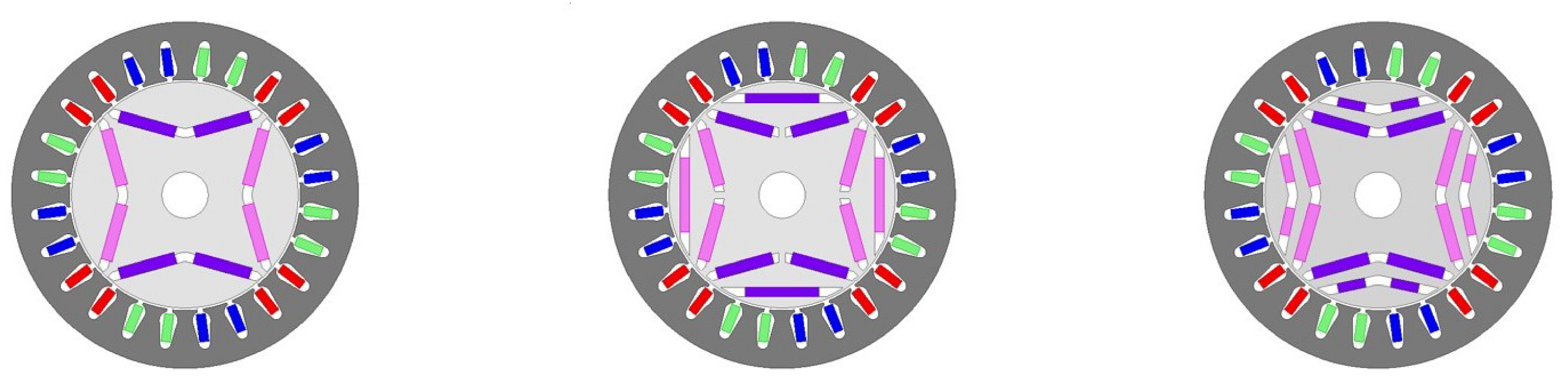
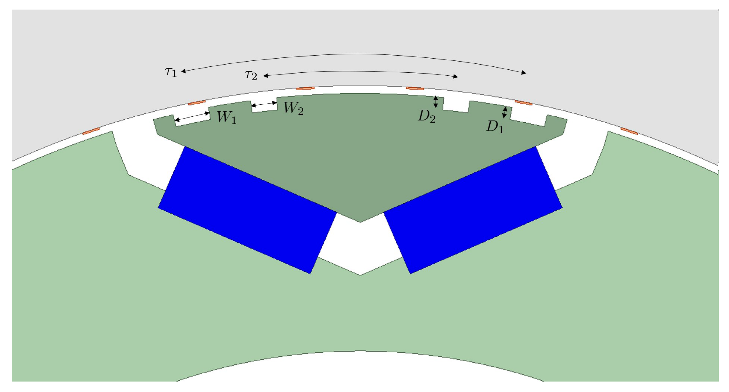
4.1. Sculpting Geometry

The sculpted rotor IPM machine geometry design space to be explored is shown on a single pole of the example machine in Figure 6. Rotor primary and secondary reluctance paths are shown in green with no bridge features. The stator, shown in gray, continues to have omitted its slot features, and distributed windings, orange, are placed within the airgap.
The primary design parameters are centered on the rotor effects, which include the ratio of primary and secondary reluctance path and sculpt features. The magnet pole arc width is varied. Up to two sets of symmetrically placed sculpt features are placed on the second reluctance path. The symmetrical feature span locations τ 1 and τ 2 define the symmetrical location of the feature in terms of its percentage of the magnet pole arc span. Single asymmetrical features are described with a similar parameter but with only one sculpt feature on the pole. In this single asymmetrical case, the feature location, τ , is set to be positive for right hand side placement and negative for the left hand side placement. The depths D 1 and D 2 are measured from the outer surface of the rotor to the root of the sculpt feature. The widths W 1 and W 2 are measured in terms of a single feature percentage of the pole span.
A Fourier analysis of design feature effects on torque harmonic analysis is presented. The phase of the torque harmonics is set with respect to the negative zero crossing of phase A back EMF, i.e., the north pole of the machine. Torque components are separated in terms of total, primary reluctance, secondary reluctance and magnet torque with both the torque amplitude and its corresponding phase.

4.2. Model Implementation

Implemented in Matlab, the analytical model in Section 3 has been utilized to explore the design space. Rotor permeances of primary reluctance, secondary reluctance, and magnet and the permanent magnet winding function are modeled spatially as the rectangular waves. Stator phase winding functions and linear turn densities are spatially modeled, and the spatial harmonic coefficients are determined with the FFT. For each rotor position, the complex rotation vector is created and applied to the stator winding and linear turn functions. With the current applied, the modified secondary reluctance path is determined from Equation (13). Radial flux density is now determined for the primary reluctance, second reluctance, and magnet paths. A broad range of phase current, control angle, and rotor sculpting features are studied. Maxwell’s stress tensor in conjunction with Equation (19) provides the ability to separate components of torque.
The analytical model is implemented utilizing both the FFT and the inverse FFT algorithms to efficiently move between frequency and spatial domains. Rotation is best performed within the frequency domain, Equation (22), and convolution is performed within the spatial domain. This provides the most efficient use of resources by a factor of five times. Results are computed over an entire electrical cycle with a sufficient number of points to provide a smooth torque waveform. The analytical model is executed within Matlab in 6.7 s, and the finite element results are executed in 20 min. Ansys Maxwell was also used to perform the finite element analysis.

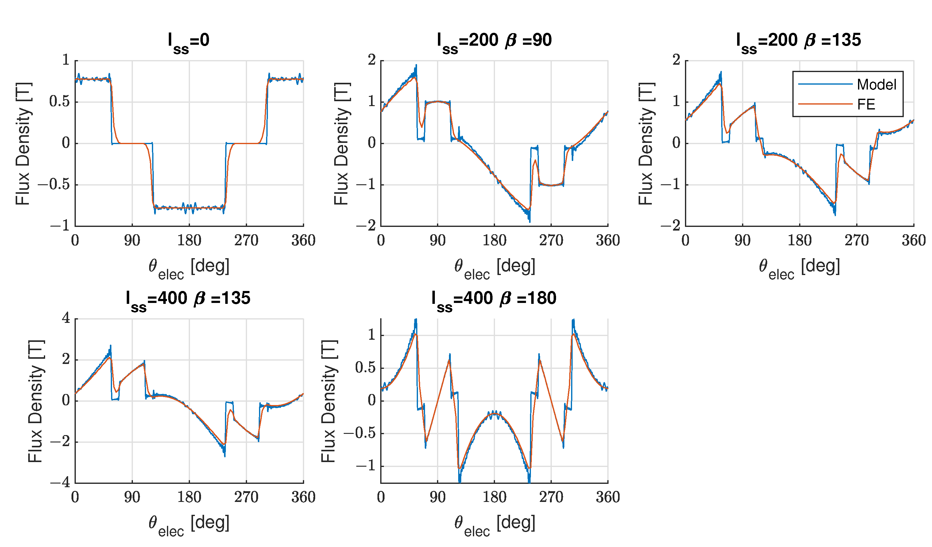
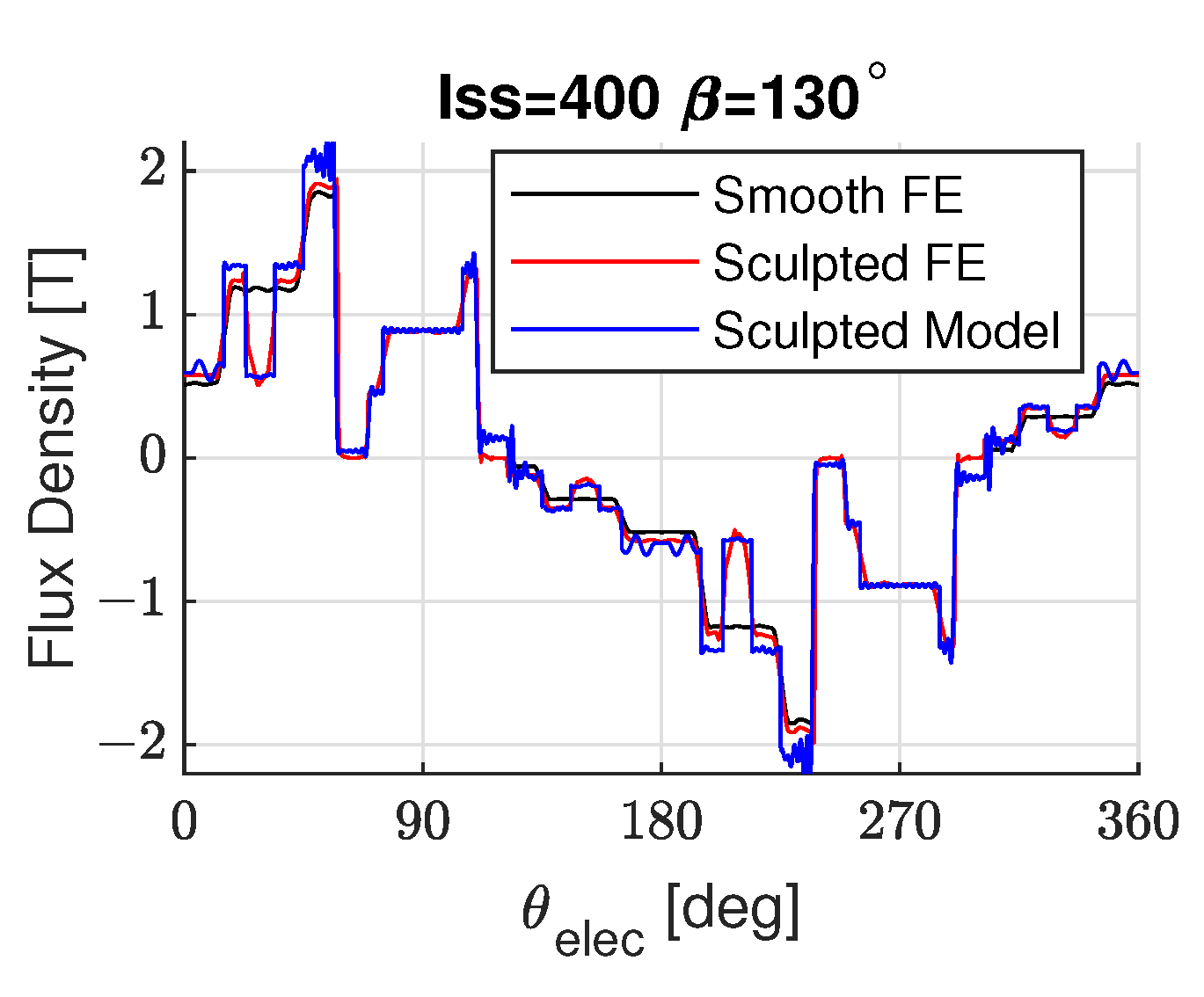
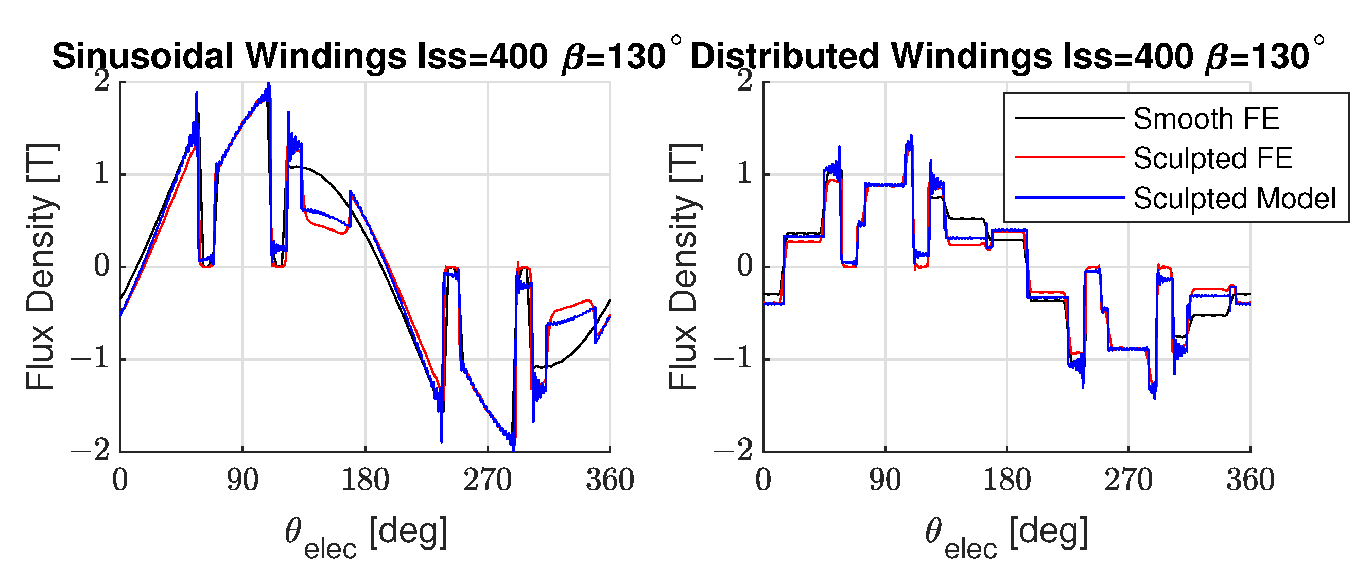
4.3. Model Validation: Radial Flux Density

This section compares the radial flux density results of the analytical model and finite elements while varying: (1) winding type, (2) current, (3) control angle, and (4) rotor sculpt features. Figure 7, Figure 8, Figure 9 and Figure 10 plot the flux density along the rotors spatial coordinate, θ , over a single pole pair. Both sinusoidal and distributed windings are compared. The q-axis, which is aligned to the rotor minimum reluctance, occurs at θ e l e c = 90 and θ e l e c = 270 . The d-axis is aligned, which is aligned to the smooth rotors permanent magnet maximum flux linkage, occurs at θ e l e c = 0 , θ e l e c = 180 , and θ e l e c = 360 . In all results, the finite element and the analytical model result in comparable flux densities.
Flux densities shown for sinusoidal windings, Figure 7, illustrate the changing airgap flux density harmonics with current and control angle. When the phase current is set to zero, only the permanent magnet field is present. As current and current angle increases, the flux density becomes more jagged, with the case of a fully negative d-axis current displaying the most harmonic content. It is clear that as the negative d-axis current becomes dominant, so do the reluctance path harmonics. Harmonic effects of the discretely distributed windings are shown in Figure 8. As current increases, so do the airgap reluctance harmonics. In all cases, the analytical model and finite element results agree with reasonable accuracy.
The effects of rotor sculpt features on the second reluctance path are shown in Figure 9 and Figure 10. A symmetrical pair of sculpt features are shown with distributed windings in Figure 9. The flux densities of the smooth rotor and sculpted rotor are plotted. Reduced flux density in the region of the sculpt features is observed, and sculpt features are located approximately at θ e l e c = 30 , 150 , 210 , 270 . This flux density from the sculpt features is conserved and redistributed across the regions of the second reluctance path.
The reluctance flux density single sculpt feature is plotted in Figure 10. Similar to the symmetrical sculpt features, the flux density is reduced in the region of the sculpt feature. In all cases, the analytical model and finite element results agree with reasonable accuracy.

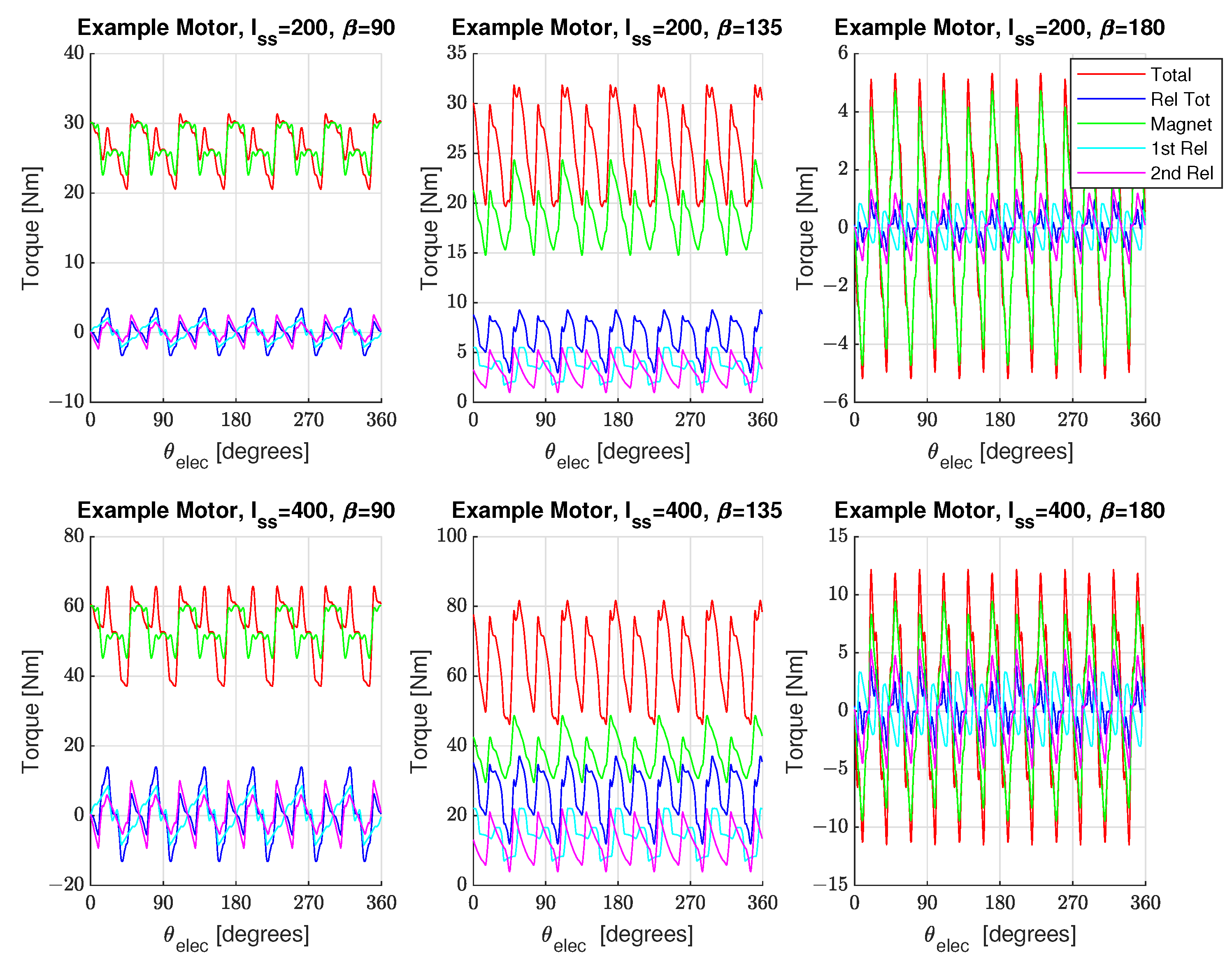
4.4. Model Validation: Torque Ripple

Torque ripple of the smooth rotor IPM, Table 2, is compared between finite element and the analytical model in Figure 11. Good agreement between the finite element and analytical models is observed. The torque ripple effects of two symmetrical rotor sculpt features are demonstrated in Figure 12, directly calculated by the analytical model, whereas the finite element model requires two runs, once with and once without sculpt features, to determine the sculpt feature effects.
Good correlation between the model and finite elements is demonstrated and shown.

4.5. Torque Ripple Components

In this section, the torque ripple results of the analytical model are studied while varying current and control angle. Figure 13 plots the torque ripple for a complete electrical cycle of the example machine. The torque components for the first reluctance path, second reluctance path, total reluctance torque, magnet torque, and total machine torque are plotted. Magnet torque and its harmonics are dominant at lower currents, but the reluctance paths cannot be ignored. As current is increased, the reluctance torque increases relative to the magnet torque. The stronger field weakening currents cause the contribution of the reluctance features torque to increase. The dominant torque harmonic orders are the 6th and 12th electrical orders. In the design, both the torque harmonic amplitudes and phases of each of the components need to be considered as the sculpt feature design will provide the counter torque at the counter phase.

5. Investigation of Design Features

In this section, the effects of design features are demonstrated to influence both torque harmonic amplitudes and phases. Carefully applied, these effects are used to design counter torque harmonics. Second reluctance path pole arc, sculpt feature type (symmetrical/asymmetrical), sculpt feature location, sculpt feature depth, and sculpt feature width can all be used to design an appropriate counter torque to reduce the machine’s torque harmonics. While mildly affecting average torque, the second reluctance path pole arc, τ p , strongly affects the phase of the 12th electrical order torque harmonic. A single pair of symmetrical sculpt features placed upon the second reluctance path pole arc reduce the average torque. Feature position provides 12th electrical order torque harmonic phasing, and the feature width and depth directly affect the torque harmonics amplitude. The single asymmetrical feature is shown to increase average torque when placed on a specific side of the second reluctance path pole arc. The asymmetrical feature placement can also be used to modify the phase of both 6th and 12th electrical order torque harmonics. Finally, feature phasor summation is shown to be effective in combining the effects of multiple design features, further providing the ability to design both the amplitude and phase of these minimizing torque harmonics. These relationships provide the necessary intuition to reduce computationally intensive design steps.

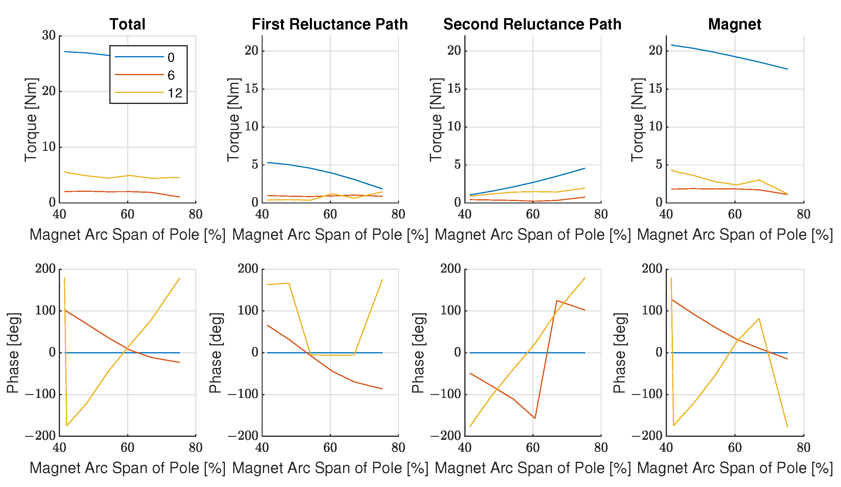
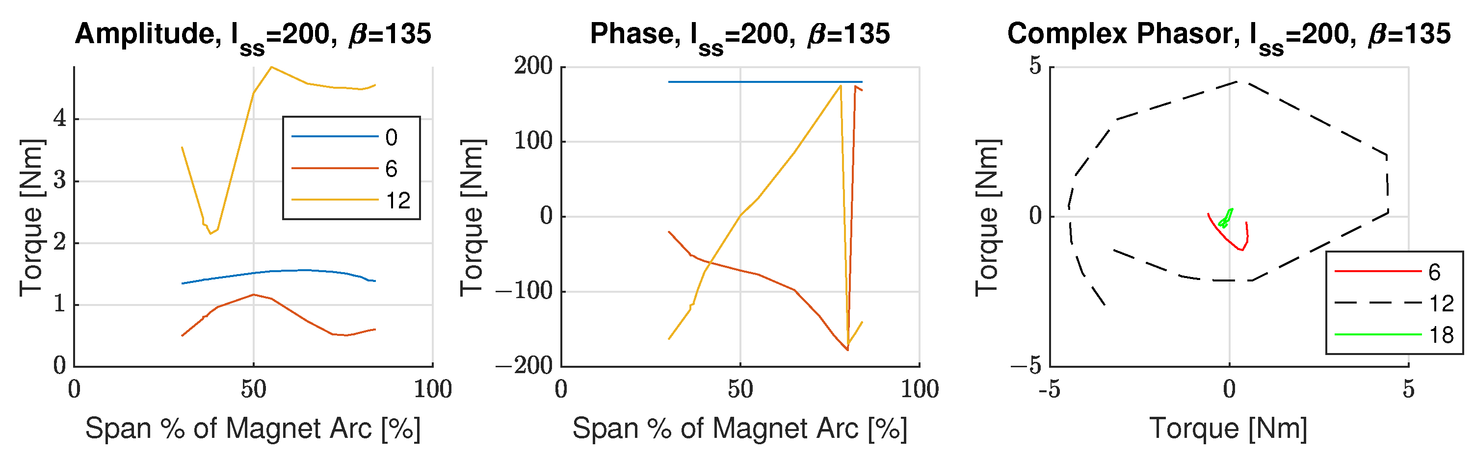
5.1. Magnet Pole Arc

Magnet pole arc span, τ m , effects upon the torque harmonics, without rotor sculpt features, are explored. Figure 14 shows the average, 6th, and 12th harmonics of torque as a function of τ m . For this case, magnet torque is dominant. Although not always the case, it is just as important to follow the trends of individual torque components. Total, first reluctance, and magnet average machine torque are reduced as the pole arc is increased, and only the second reluctance torque increases the average torque. The 12th order torque harmonic is dominant, with primary contributions from the magnet and the second reluctance path, whereas the 6th order torque harmonic is mostly contributed to by the primary reluctance and magnet. Rotor geometry has a strong influence on the phase of the 12th order torque harmonics, whereas the 6th harmonic is less affected by rotor geometry.

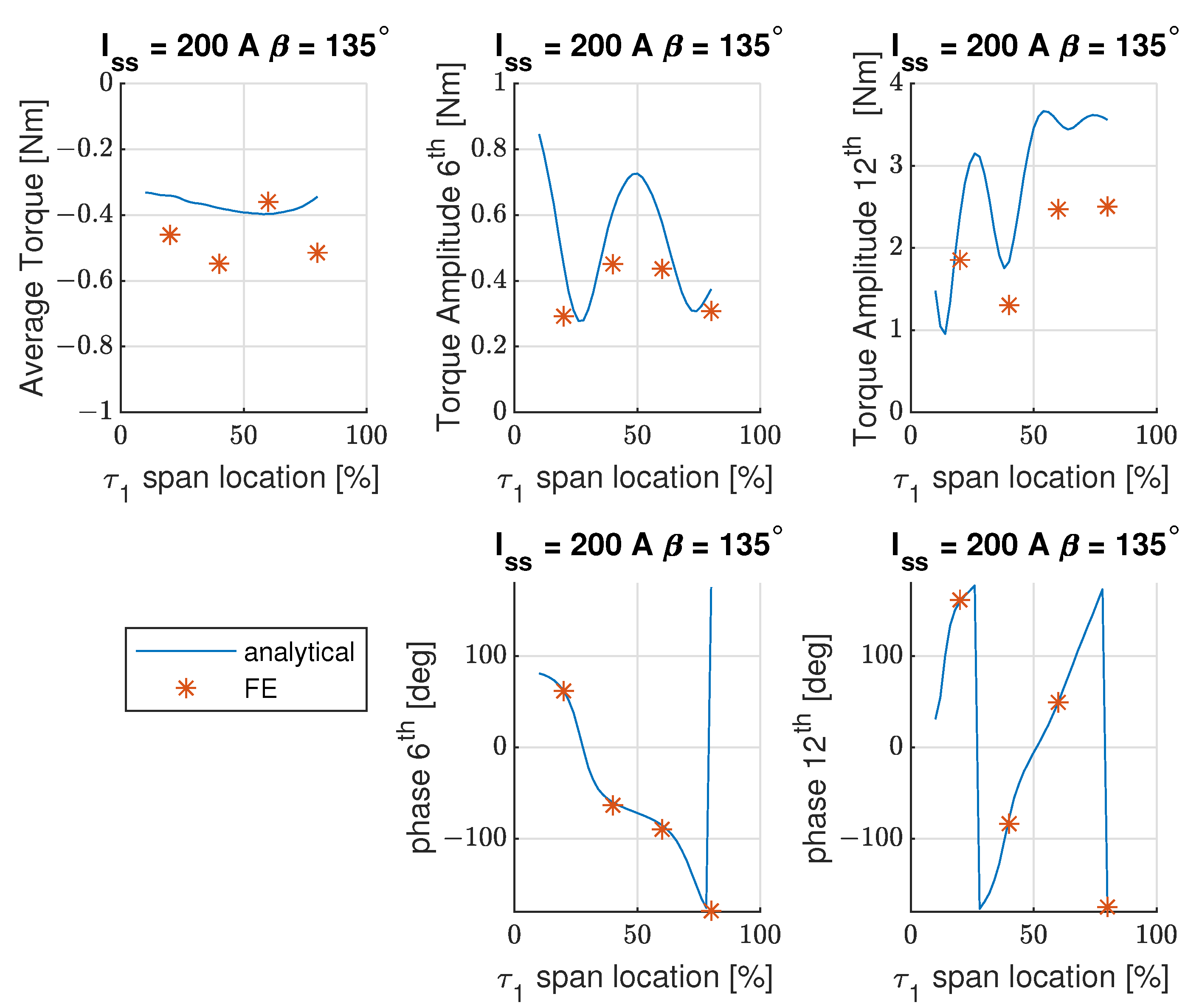
5.2. Single Pair Symmetrical Rotor Sculpt Feature

A single symmetrical rotor sculpt feature torque is studied in Figure 15, Figure 16 and Figure 17. Only the effects of the sculpt feature torque are plotted. In Figure 15 and Figure 16, a single sculpt feature position is varied, with fixed width, W 1 , and fixed depth, D 1 , along the magnet pole arc. Rotor sculpt features have a negative effect upon average torque, as the phase is 180 out of phase with the smooth rotor average torque. Figure 15 compares the analytical model to finite elements and shows precise agreement with the phase and matching trends for torque amplitude. Using a wider feature width, D 1 , Figure 16 translates amplitude and phase plots to a phasor representation. The 12th harmonic is clearly the dominant torque in both amplitudes and choice of phase.
Figure 17 includes the sculpt features width and depth effects. Increasing sculpt feature width, W 1 , and/or the sculpt features depth, D 1 , increases the amplitude of the sculpt features torque harmonic. The primary influence on the torque harmonic amplitude is the width of the sculpt feature. Sculpt feature width and depth have no effect on the torque harmonics phase.

5.3. Single Asymmetrical Rotor Sculpt Feature

A single sculpt feature resulting in asymmetrical placement upon the rotor surface is studied in this section. Similar parameters D 1 , W 1 , and τ 1 are used to describe the features width, depth, and location. In the asymmetrical case, the location, τ 1 , is described with the same location parameter, where in this case, a positive τ 1 results on the right side of Figure 6 and a negative τ 1 results in sculpt feature placement on the left hand side. Figure 18 compares the model to finite element and shows precise agreement with phase and matching trends for torque amplitude. In the asymmetric sculpt feature case, a torque improvement is possible due to the aligned axis effect from τ 1 > 0 . The placement of the sculpt feature allows for placement of the torque harmonic phase angle across a broad range of phases. Negative values of τ 1 result in the largest amplitudes of the 12th electrical torque harmonic.

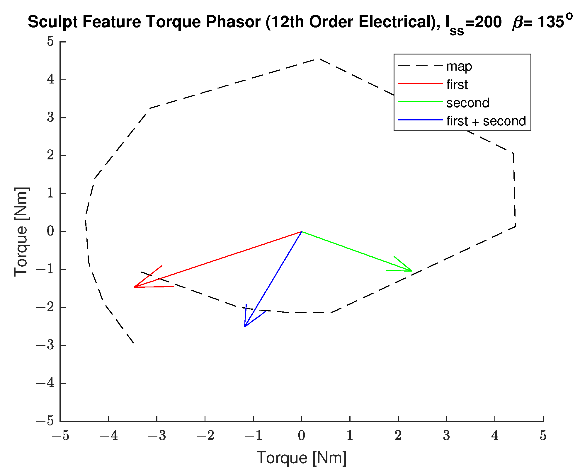
5.4. Two Symmetrical Rotor Sculpt Features

More than one symmetrical rotor sculpt feature can be used. In this section, it is shown that the components of a first symmetrical feature can be combined with that of the second symmetrical rotor sculpt feature. The MMF-permeance model is validated by comparing to finite element results in Figure 12.
To illustrate this concept, the parameters of the two sculpt feature sets of Figure 6 are shown in Table 3. Through vector summation, the two vectors were used to create a 12th order counter torque with a phase of 116 .
Figure 19 illustrates the first (red) and second 12th order electrical torque (green) phasors. The two phasors combine to create the effective total phasor (blue). This phasor summation is plotted along with the torque complex mapping of the previous single feature design sweep. These symmetrical rotor sculpt features are designed to mitigate the 12th order electrical torque harmonics to near zero. A single feature or multiple features can be designed to minimize the torque ripple. The sculpt features are not without consequence, as the average torque is negatively affected.

6. Conclusions

This paper has presented an analytical modeling and design approach to reduce torque ripple with rotor sculpt features. By carefully placing rotor sculpt features and rotor barrier features, average torque can be maintained while minimizing torque harmonics. Contributions of this paper include:
  • A new analytical winding factor modeling approach for the single V IPM machine relating the rotor’s first reluctance feature, second reluctance feature, permanent magnet features, sculpt features, and stator windings to the resulting torque harmonics;
  • An analytical modeling approach accounting for both symmetrical and torque aligning asymmetrical rotor sculpt features;
  • Results from the analytical model providing valuable insights for identifying rotor feature design improvements;
  • Design approach for placement of rotor sculpt features to minimize torque ripple while maintaining average torque;
  • Demonstration of close agreement of radial flux density and torque harmonics results between the analytical model and that of finite element results.
These results enable better design insight and an efficient design process through use of an analytical model.

Author Contributions

Investigation, S.H.; supervision, E.S. Both authors have read and agreed to the published version of the manuscript.

Funding

This research received no external funding.

Institutional Review Board Statement

Not applicable.

Informed Consent Statement

Not applicable.

Data Availability Statement

Data sharing not applicable.

Conflicts of Interest

The authors declare no conflict of interest.

References

  1. Momen, F.; Rahman, K.; Son, Y.; Savagian, P. Electrical propulsion system design of Chevrolet Bolt battery electric vehicle. In Proceedings of the 2016 IEEE Energy Conversion Congress and Exposition (ECCE), Milwaukee, WI, USA, 18–22 September 2016; pp. 1–8. [Google Scholar]
  2. Namiki, K.; Murota, K.; Shoji, M. High Performance Motor and Inverter System for a Newly Developed Electric Vehicle. SAE Tech. Pap. Ser. 2018. [Google Scholar] [CrossRef]
  3. Jurkovic, S.; Rahman, K.; Bae, B.; Patel, N.; Savagian, P. Next generation chevy volt electric machines; design, optimization and control for performance and rare-earth mitigation. In Proceedings of the 2015 IEEE Energy Conversion Congress and Exposition (ECCE), Montreal, QC, Canada, 20–24 September 2015; pp. 5219–5226. [Google Scholar]
  4. Kanayama, T.; Yanagida, E.; Kano, S.; Geller, B.; Nakao, Y.; Fukao, M. Development of New Hybrid System for Mid-Size SUV. SAE Tech. Pap. Ser. 2020. [Google Scholar] [CrossRef]
  5. Jensen, W.R.; Pham, T.Q.; Foster, S.N. Comparison of Multi-objective Optimization Methods Applied to Electrical Machine Design. In Evolutionary Multi-Criterion Optimization; Deb, K., Goodman, E., Coello Coello, C.A., Klamroth, K., Miettinen, K., Mostaghim, S., Reed, P., Eds.; Springer International Publishing: Cham, Switzerland, 2019; pp. 719–730. [Google Scholar]
  6. Han, S.; Jahns, T.M.; Soong, W.L. Torque Ripple Reduction in Interior Permanent Magnet Synchronous Machines Using the Principle of Mutual Harmonics Exclusion. In Proceedings of the 2007 IEEE Industry Applications Annual Meeting, New Orleans, LA, USA, 23–27 September 2007; pp. 558–565. [Google Scholar] [CrossRef]
  7. Pellegrino, G.; Guglielmi, P.; Vagati, A.; Villata, F. Core Losses and Torque Ripple in IPM Machines: Dedicated Modeling and Design Tradeoff. IEEE Trans. Ind. Appl. 2010, 46, 2381–2391. [Google Scholar] [CrossRef] [Green Version]
  8. Vagati, A.; Pastorelli, M.; Francheschini, G.; Petrache, S.C. Design of low-torque-ripple synchronous reluctance motors. IEEE Trans. Ind. Appl. 1998, 34, 758–765. [Google Scholar] [CrossRef]
  9. Zhu, Z.; Howe, D.; Bolte, E.; Ackermann, B. Instantaneous magnetic field distribution in brushless permanent magnet DC motors. I. Open-circuit field. IEEE Trans. Magn. 1993, 29, 124–135. [Google Scholar] [CrossRef]
  10. Zhu, Z.; Howe, D.; Chan, C. Improved analytical model for predicting the magnetic field distribution in brushless permanent-magnet machines. IEEE Trans. Magn. 2002, 38, 229–238. [Google Scholar] [CrossRef] [Green Version]
  11. Tang, C.; Shen, M.; Fang, Y.; Pfister, P.D. Comparison of Subdomain, Complex Permeance, and Relative Permeance Models for a Wide Family of Permanent-Magnet Machines. IEEE Trans. Magn. 2021, 57, 1–5. [Google Scholar] [CrossRef]
  12. Mi, C.; Filippa, M.; Liu, W.; Ma, R. Analytical method for predicting the air-gap flux of interior-type permanent-magnet machines. IEEE Trans. Magn. 2004, 40, 50–58. [Google Scholar] [CrossRef]
  13. Tariq, A.R.; Nino-Baron, C.E.; Strangas, E.G. Iron and Magnet Losses and Torque Calculation of Interior Permanent Magnet Synchronous Machines Using Magnetic Equivalent Circuit. IEEE Trans. Magn. 2010, 46, 4073–4080. [Google Scholar] [CrossRef]
  14. Dajaku, G.; Gerling, D. Air-Gap Flux Density Characteristics of Salient Pole Synchronous Permanent-Magnet Machines. IEEE Trans. Magn. 2012, 48, 2196–2204. [Google Scholar] [CrossRef]
  15. Koo, B.; Nam, K. Analytical Torque Ripple Prediction Using Air-Gap Permeance and MMF Functions in PM Synchronous Motors. In Proceedings of the 2018 21st International Conference on Electrical Machines and Systems (ICEMS), Jeju, Korea, 7 October 2018; pp. 302–307. [Google Scholar] [CrossRef]
  16. Pina, A.J.; Xu, L. Modeling of synchronous reluctance motors aided by permanent magnets with asymmetric rotor poles. In Proceedings of the 2015 IEEE International Electric Machines Drives Conference (IEMDC), Coeur d’Alene, ID, USA, 10–13 May 2015; pp. 412–418. [Google Scholar] [CrossRef]
  17. Li, Q.; Fan, T.; Wen, X. Armature-Reaction Magnetic Field Analysis for Interior Permanent Magnet Motor Based on Winding Function Theory. IEEE Trans. Magn. 2013, 49, 1193–1201. [Google Scholar] [CrossRef]
  18. Aggarwal, A.; Strangas, E.G.; Agapiou, J. Analysis of Unbalanced Magnetic Pull in PMSM Due to Static Eccentricity. In Proceedings of the 2019 IEEE Energy Conversion Congress and Exposition (ECCE), Baltimore, MD, USA, 29 September–3 October 2019; pp. 4507–4514. [Google Scholar]
  19. Aggarwal, A.; Strangas, E.G. Review of Detection Methods of Static Eccentricity for Interior Permanent Magnet Synchronous Machine. Energies 2019, 12, 4105. [Google Scholar] [CrossRef] [Green Version]
  20. Du, Z.S.; Lipo, T.A. Torque Ripple Minimization in Interior Permanent Magnet Machines Using Axial Pole Shaping. In Proceedings of the 2018 IEEE Energy Conversion Congress and Exposition (ECCE), Portland, OR, USA, 23–27 September 2018; pp. 6922–6929. [Google Scholar] [CrossRef]
  21. Jang, S.; Park, H.; Choi, J.; Ko, K.; Lee, S. Magnet Pole Shape Design of Permanent Magnet Machine for Minimization of Torque Ripple Based on Electromagnetic Field Theory. IEEE Trans. Magn. 2011, 47, 3586–3589. [Google Scholar] [CrossRef]
  22. Lee, S.; Kang, G.; Hur, J.; Kim, B. Stator and Rotor Shape Designs of Interior Permanent Magnet Type Brushless DC Motor for Reducing Torque Fluctuation. IEEE Trans. Magn. 2012, 48, 4662–4665. [Google Scholar] [CrossRef]
  23. Evans, S.A. Salient pole shoe shapes of interior permanent magnet synchronous machines. In Proceedings of the The XIX International Conference on Electrical Machines—ICEM 2010, Rome, Italy, 6–8 September 2010; pp. 1–6. [Google Scholar] [CrossRef]
  24. Seo, U.; Chun, Y.; Choi, J.; Han, P.; Koo, D.; Lee, J. A Technique of Torque Ripple Reduction in Interior Permanent Magnet Synchronous Motor. IEEE Trans. Magn. 2011, 47, 3240–3243. [Google Scholar] [CrossRef]
  25. Wang, K.; Zhu, Z.Q.; Ombach, G.; Chlebosz, W. Optimal rotor shape with third harmonic for maximizing torque and minimizing torque ripple in IPM motors. In Proceedings of the 2012 XXth International Conference on Electrical Machines, Marseille, France, 2–5 September 2012; pp. 397–403. [Google Scholar] [CrossRef]
  26. Kioumarsi, A.; Moallem, M.; Fahimi, B. Mitigation of Torque Ripple in Interior Permanent Magnet Motors by Optimal Shape Design. IEEE Trans. Magn. 2006, 42, 3706–3711. [Google Scholar] [CrossRef]
  27. Shimizu, Y.; Morimoto, S.; Sanada, M.; Inoue, Y. Reduction of torque ripple in double-layered IPMSM for automotive applications by rotor structure modification. In Proceedings of the 2017 IEEE 12th International Conference on Power Electronics and Drive Systems (PEDS), Honolulu, HI, USA, 12–15 December 2017; pp. 429–434. [Google Scholar] [CrossRef]
  28. Yamazaki, K.; Kumagai, M.; Ikemi, T.; Ohki, S. A Novel Rotor Design of Interior Permanent-Magnet Synchronous Motors to Cope with Both Maximum Torque and Iron-Loss Reduction. IEEE Trans. Ind. Appl. 2013, 49, 2478–2486. [Google Scholar] [CrossRef]
  29. Kang, G.; Son, Y.; Kim, G.; Hur, J. A Novel Cogging Torque Reduction Method for Interior-Type Permanent-Magnet Motor. IEEE Trans. Ind. Appl. 2009, 45, 161–167. [Google Scholar] [CrossRef]
  30. Liang, J.; Parsapour, A.; Moallem, M.; Fahimi, B. Asymmetric Rotor Surface Design in Interior Permanent Magnet Synchronous Motors for Torque Ripple Mitigation. In Proceedings of the 2019 IEEE International Electric Machines Drives Conference (IEMDC), San Deigo, CA, USA, 15 May 2019; pp. 727–732. [Google Scholar] [CrossRef]
  31. Liang, J.; Parsapour, A.; Yang, Z.; Caicedo-Narvaez, C.; Moallem, M.; Fahimi, B. Optimization of Air-Gap Profile in Interior Permanent-Magnet Synchronous Motors for Torque Ripple Mitigation. IEEE Trans. Transp. Electrif. 2019, 5, 118–125. [Google Scholar] [CrossRef]
  32. Yamazaki, K.; Utsunomiya, K. Mechanism of Torque Ripple Generation by Time and Space Harmonic Magnetic Fields in Interior Permanent Magnet Synchronous Motors. In Proceedings of the 2020 International Conference on Electrical Machines (ICEM), Virtual, 23–26 August 2020; Volume 1, pp. 232–238. [Google Scholar] [CrossRef]
  33. Islam, R.; Husain, I.; Fardoun, A.; McLaughlin, K. Permanent-Magnet Synchronous Motor Magnet Designs with Skewing for Torque Ripple and Cogging Torque Reduction. IEEE Trans. Ind. Appl. 2009, 45, 152–160. [Google Scholar] [CrossRef]
  34. Cao, R.; Mi, C.; Cheng, M. Quantitative Comparison of Flux-Switching Permanent-Magnet Motors with Interior Permanent Magnet Motor for EV, HEV, and PHEV Applications. IEEE Trans. Magn. 2012, 48, 2374–2384. [Google Scholar] [CrossRef]
  35. Wu, D.; Zhu, Z.Q. Design Tradeoff Between Cogging Torque and Torque Ripple in Fractional Slot Surface-Mounted Permanent Magnet Machines. IEEE Trans. Magn. 2015, 51, 1–4. [Google Scholar] [CrossRef]
  36. Liu, X.; Chen, H.; Zhao, J.; Belahcen, A. Research on the Performances and Parameters of Interior PMSM Used for Electric Vehicles. IEEE Trans. Ind. Electron. 2016, 63, 3533–3545. [Google Scholar] [CrossRef]
  37. Pellegrino, G.; Vagati, A.; Guglielmi, P.; Boazzo, B. Performance Comparison Between Surface-Mounted and Interior PM Motor Drives for Electric Vehicle Application. IEEE Trans. Ind. Electron. 2012, 59, 803–811. [Google Scholar] [CrossRef] [Green Version]
  38. Pellegrino, G.; Vagati, A.; Boazzo, B.; Guglielmi, P. Comparison of Induction and PM Synchronous Motor Drives for EV Application Including Design Examples. IEEE Trans. Ind. Appl. 2012, 48, 2322–2332. [Google Scholar] [CrossRef] [Green Version]
  39. Yang, Z.; Shang, F.; Brown, I.P.; Krishnamurthy, M. Comparative Study of Interior Permanent Magnet, Induction, and Switched Reluctance Motor Drives for EV and HEV Applications. IEEE Trans. Transp. Electrif. 2015, 1, 245–254. [Google Scholar] [CrossRef]
  40. Zarko, D.; Ban, D.; Lipo, T. Analytical calculation of magnetic field distribution in the slotted air gap of a surface permanent-magnet motor using complex relative air-gap permeance. IEEE Trans. Magn. 2006, 42, 1828–1837. [Google Scholar] [CrossRef]
  41. Wu, L.J.; Zhu, Z.Q.; Staton, D.; Popescu, M.; Hawkins, D. An Improved Subdomain Model for Predicting Magnetic Field of Surface-Mounted Permanent Magnet Machines Accounting for Tooth-Tips. IEEE Trans. Magn. 2011, 47, 1693–1704. [Google Scholar] [CrossRef]
  42. Kim, B.; Lipo, T.A. Analysis of a PM Vernier Motor with Spoke Structure. IEEE Trans. Ind. Appl. 2016, 52, 217–225. [Google Scholar] [CrossRef]
  43. Dajaku, G. Open-Circuit Air-Gap Field Calculation of a New PM Machine Having a Combined SPM and Spoke-Type Magnets. IEEE Trans. Magn. 2020, 56, 1–9. [Google Scholar] [CrossRef]
  44. Dajaku, G. Analytical Analysis of Electromagnetic Torque and Magnet Utilization Factor for Two Different PM Machines with SPM and HUPM Rotor Topologies. IEEE Trans. Magn. 2021, 57, 1–9. [Google Scholar] [CrossRef]
  45. Kwon, J.W.; Li, M.; Kwon, B.I. Design of V-Type Consequent-Pole IPM Machine for PM Cost Reduction with Analytical Method. IEEE Access 2021, 9, 77386–77397. [Google Scholar] [CrossRef]
  46. Hoang, K.D. Simplified Analytical Model for Rapid Evaluation of Interior PM Traction Machines Considering Magnetic Nonlinearity. IEEE Open J. Ind. Electron. Soc. 2020, 1, 340–354. [Google Scholar] [CrossRef]
  47. Hu, W.; Zhang, X.; Lei, Y.; Du, Q.; Shi, L.; Liu, G. Analytical Model of Air-Gap Field in Hybrid Excitation and Interior Permanent Magnet Machine for Electric Logistics Vehicles. IEEE Access 2020, 8, 148237–148249. [Google Scholar] [CrossRef]
  48. Ghahfarokhi, M.M.; Amiri, E.; Boroujeni, S.T.; Aliabad, A.D. On-Load Analytical Modeling of Slotted Interior Magnet Synchronous Machines Using Magnetic Islands Method. IEEE Access 2020, 8, 95360–95367. [Google Scholar] [CrossRef]
  49. Hajdinjak, M.; Miljavec, D. Analytical Calculation of the Magnetic Field Distribution in Slotless Brushless Machines with U-Shaped Interior Permanent Magnets. IEEE Trans. Ind. Electron. 2020, 67, 6721–6731. [Google Scholar] [CrossRef]
  50. Mirazimi, M.S.; Kiyoumarsi, A. Magnetic Field Analysis of SynRel and PMASynRel Machines with Hyperbolic Flux Barriers Using Conformal Mapping. IEEE Trans. Transp. Electrif. 2020, 6, 52–61. [Google Scholar] [CrossRef]
  51. Hayslett, S.; Strangas, E. Design and Analysis of Aligned Axis Interior Permanent Magnet Machines Considering Saturation. In Proceedings of the 2019 IEEE International Electric Machines Drives Conference (IEMDC), San Diego, CA, USA, 12–15 May 2019; pp. 686–692. [Google Scholar] [CrossRef]
  52. Thike, R.; Pillay, P. Mathematical Model of an Interior PMSM with Aligned Magnet and Reluctance Torques. IEEE Trans. Transp. Electrif. 2020, 6, 647–658. [Google Scholar] [CrossRef]
  53. Toliyat, H.A. Electric Machines: Modeling, Condition Monitoring, and Fault Diagnosis; CRC Press: Boca Raton, FL, USA, 2017. [Google Scholar]
  54. Taghipour Boroujeni, S.; Zamani, V. A Novel Analytical Model for No-Load, Slotted, Surface-Mounted PM Machines: Air Gap Flux Density and Cogging Torque. IEEE Trans. Magn. 2015, 51, 1–8. [Google Scholar] [CrossRef]
  55. Cheng, D.K. Field and Wave Electromagnetics; Addison-Wesley: Boston, MA, USA, 1989. [Google Scholar]
Figure 1. IPM rotor types: single V (left), delta (center), double V (right).
Energies 14 05109 g001
Figure 2. IPM flux paths: first reluctance path (solid blue), second reluctance path (dashed blue), and magnet path (solid red).
Energies 14 05109 g002
Figure 3. Vector diagram of IPM rotor with unaligned magnet, with variables: ϕ rotor position, θ rotor spatial coordinate, δ magnet alignment, ω rotor speed.
Energies 14 05109 g003
Figure 4. Conductor locations and permeability functions, (red) phase A conductor, (blue) phase B conductor locations, (green) phase C conductor location, (gold) first reluctance path permeability function, (lavender) second reluctance path permeability functions, (purple) magnet path permeability function, (gray) equivalent permanent magnet conductor locations.
Energies 14 05109 g004
Figure 5. Sculpted Rotor Reluctance Counter Dipole Current.
Energies 14 05109 g005
Figure 6. Rotor sculpt features.
Energies 14 05109 g006
Figure 7. Radial flux densities with sinusoidally distributed windings (N = 200) at various currents and control angles.
Energies 14 05109 g007
Figure 8. Radial flux densities with distributed windings (2 SPP) at various currents and control angles.
Energies 14 05109 g008
Figure 9. Radial flux densities with single symmetrical sculpt feature located at τ 1 = 50 % , W 1 = 10 % , and D 1 = 1.2 mm.
Energies 14 05109 g009
Figure 10. Radial flux densities (reluctance only) with single asymmetrical sculpt feature located at τ = 50 % , W = 20 % , and D = 1.2 mm.
Energies 14 05109 g010
Figure 11. Smooth rotor IPM torque ripple.
Energies 14 05109 g011
Figure 12. Sculpt feature torque ripple.
Energies 14 05109 g012
Figure 13. Analytical model torque ripple components at various control angles.
Energies 14 05109 g013
Figure 14. Effects of magnet pole arc τ p loaded at I s s = 200 and β = 135 .
Energies 14 05109 g014
Figure 15. Symmetrical sculpt feature effects compared to finite elements: D 1 = 1.2 mm, W 1 = 5 % .
Energies 14 05109 g015
Figure 16. Symmetrical sculpt feature effects with phasor diagram: D 1 = 1.2 mm, W 1 = 9 % .
Energies 14 05109 g016
Figure 17. Sculpt feature effects N = 1.
Energies 14 05109 g017
Figure 18. Single asymmetrical sculpt feature effects with phasor diagram: D 1 = 1.2 mm, W 1 = 5 % .
Energies 14 05109 g018
Figure 19. Two sculpt features of 12th order electrical torque phasor plot.
Energies 14 05109 g019
Table 1. Permeance functions and related minimum and maximum airgaps.
Permeance TermMinimum AirgapMaximum Airgap
First Reluctance Path l g l g + l m
Second Reluctance Path l g
Permanent Magnet Path l g + l m
Table 2. Example motor parameters.
ParameterValueUnit
Pole Pairs4
Stator Slots48
Number of Phases3
Stack Length83mm
Rotor Diameter161.15mm
Airgap Length0.75mm
Magnet Pole Arc % of Pole Pitch63.8%
Barrier TypeSingle V
Magnet Thickness6.48mm
Magnet Width16 × 2mm
Permanent Magnet Remnant1.19T
Permeability of IronH/m
Permeability of Bridge Features 4 π · 10 7 H/m
Table 3. Two sculpt feature parameters.
FeatureValueUnit
τ 1 82% of magnet pole arc
τ 2 46.5% of magnet pole arc span
W 1 5.5% of pole span
W 2 5.5% of pole span
D 1 1.2mm
D 2 1.2mm
Publisher’s Note: MDPI stays neutral with regard to jurisdictional claims in published maps and institutional affiliations.

