Abstract
During wireless charging, the transmission distance of electric vehicles varies, resulting in different levels of electromagnetic field leakage. An improved active shielding technology, the double-coil dynamic shielding technology, is proposed in this paper for wireless power transfer (WPT) systems with different transmission distances. Modeling, simulation, and experiments are performed for the WPT system with a double-coil dynamic shielding scheme and compared with other cases. The results show that the proposed double-coil dynamic shielding scheme is able to shield approximately 70% of the electromagnetic field leakage for WPT systems at different transmission distances. In addition, it essentially causes no degradation in transmission efficiency (only 3.1%). The effectiveness and feasibility of the proposed scheme are verified.
1. Introduction
The promotion of electric vehicles [1] (EVs) is key to the realization of sustainable transportation. Initially, the main power transfer technologies involved battery exchange and wired charging. While battery exchange is operationally convenient, battery storage safety is still a major challenge. Wired charging, although avoiding storage safety issues, also brings some inconveniences to the utilization of EVs, such as aging wires, the risk of electric shock, and poor contact [2,3]. For this purpose, new technologies to improve comfort and safety are being investigated, of which wireless power transfer (WPT) technology is certainly one of the most appealing [4,5,6,7].
However, one of the crucial challenges of WPT systems when applied to EVs relates to the electromagnetic field (EMF) safety issues that can be caused by human exposure to severe EMFs [8,9,10]. During the transmission of power from the transmitting coil to the receiving coil, a portion of the EMF is radiated around the WPT system, called EMF leakage. The generation of EMF leakage not only has an impact on the devices and parts around the WPT system. It also jeopardizes the health and safety of human beings by generating current and heat inside the human body, which can cause irritation to muscles, nerves, tissues, and organs [11,12,13]. Therefore, the electromagnetic safety issue become an essential and critical point in the design process of WPT systems, which must ensure that the EMF leakage levels comply with the International Commission on Non-Ionizing Radiation Protection (ICNIRP) standards and guidelines [14].
Many studies have been conducted in the past few years on electromagnetic shielding technology to reduce EMF leakage from WPT systems [15,16,17,18]. Currently, there are three main shielding measures to reduce EMF leakage: passive shielding, resonant reactive current loop, and active shielding [19,20]. Features of these shielding technologies are shown in Appendix B. The present study focuses on passive shielding technology [21,22]. This suppresses electromagnetic radiation by using metallic materials to generate an EMF in the opposite direction to the one generated by the coupling coil in the form of eddy currents [23].
Despite its simplicity of operation and ease of implementation, this technology has obvious drawbacks. The use of metallic materials leads to an increase in the weight of the system, reducing the coupling coefficient and also increasing the losses [24]. Therefore, an improved passive shielding technology, resonant reactive current loop, has been proposed [25]. Its operation is based on the principle that, by placing a closed-loop coil with matching capacitance around the transmitting and receiving coils, respectively, a canceling EMF opposite to the incident field is generated to significantly reduce the EMF leakage of the WPT system. Resonant reactive current loop overcomes the shortcomings of traditional passive shielding and achieves good shielding with a small additional volume and less impact on the power transmission efficiency.
Although the method is simple in structure, the shielding coil achieves only 53% shielding effectiveness against EMF leakage, owing to the fact that the power of the shielding coil is derived from the induced EMF, yielding a limited cancellation of EMF [26]. For cases with higher shielding requirements, active shielding technology [27,28] has obvious advantages over the two technologies mentioned above. The principle of active shielding technology is to eliminate EMF leakage by generating a canceling EMF with a vector direction opposite to the incident EMF. In this technology, the active shielding coil arranged at the periphery of the transmitting coil is provided with an independent power supply, and satisfactory shielding effectiveness is achieved by adjusting the power supply.
In previous studies, a single active shielding coil around the transmitting coil was commonly taken into consideration. Therefore, the radius of the active coil should be greater than the radius of the transmitting coil [29]. With regard to the current strength and phase magnitude, the current strength should be selected based on the EMF calculation of the WPT system, while the phase should be opposite to the phase of the transmitting coil current. Therefore, the active coil generates a canceling EMF in the opposite direction of the EMF of the transmitting coil, which leads to a weakening of the EMF leakage [30]. However, the total EMF received by the receiving coil is the sum of the EMFs of the active shielding coil and transmitting coil. The algebraic sum of the two EMFs in opposite directions is significantly lower than the EMF when only the transmitting coil is present. Therefore, the addition of the active shielding coil negatively affects the transmission performance of the WPT system.
To minimize the degradation in transmission performance from the active shielding coil, multiple active coils can be considered. In this case, the geometry of each active coil, its placement, and parameters such as current strength and phase need to be discussed in more depth.
In addition, in previous WPT systems for EVs, the shielding function is usually limited to static shielding, i.e., discussing the shielding effectiveness at a fixed transmission distance [31,32]. However, for different EVs, the distance between the chassis of vehicles and the ground transmitting coil is not consistent. As a result, the power transmission distance during the charging process is inconsistent, resulting in varying EMF leakage levels.
In order to improve the wide applicability of shielding technology, this paper proposes an improved active shielding technology—the double-coil dynamic shielding scheme—for different transmission distances of EVs. Firstly, the active shielding structure with double shielding coils is discussed. Secondly, a modeling analysis of the improved, dynamically shielding WPT system is performed. Finally, simulations and experiments are performed on the proposed shielding structure to verify the effectiveness of the double-coil dynamic shielding scheme.
2. Double-Coil Active Shielding Technology
2.1. Shielding Structure
To overcome the negative impact of the addition of an active shielding coil on transmission efficiency, an improved double-coil active shielding structure is used in this paper—with two half-loops instead of a single active shielding coil—and the structure diagram is presented in Figure 1.
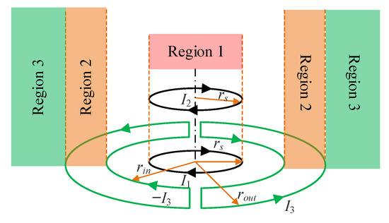
Figure 1.
Double-coil active shielding structure.
It is apparent from Figure 1 that each half-loop is equivalent to half of a circle, with its inner radius denoted by rin and outer radius denoted by rout. Two half-loops are installed around the transmitting coil, and the radius of the transmitting coil is rs; thus, it is obvious that rin > rs. To facilitate the discussion at a later stage, the regions in Figure 1 are divided as follows: inside the transmitting coil, i.e., r < rs, is noted as region 1; excluding the transmitting coil part, the region inside the active shielding coil, i.e., rin < r < rout, is denoted as region 2; outside the active shielding coil, i.e., r > rout, is noted as region 3.
Observing the direction of shielding coil currents in Figure 1, it can be seen that in region 3, the EMF generated by the two half-loops is in the opposite direction of the EMF generated by the transmitting coil, which creates a weakening effect on the total EMF in region 3. Moreover, in region 1, the EMF generated by the two shielding coils is consistent with the direction of the EMF of the transmitting coil. Compared with the traditional single shielding coil, the negative impact of the two half-loops on the performance of WPT system is reduced. It achieves a dual effect, reducing the EMF leakage of the WPT system while increasing the transmission efficiency.
2.2. Magnetic Field Calculation
In this work, the configuration described in Figure 1 is considered. Since the currents flowing in the radial direction of the two half-loops are opposite (as shown in Figure 1), the EMFs generated by these two current segments can be ignored. Consequently, in the process of calculating EMF, the structure shown in Figure 1 can be simplified. The simplified model is illustrated in Figure 2: neglecting the radial current segments, the two half-loops are replaced by two concentric circular coils with the same current but opposite phase. The inner radius and outer radius of the two concentric circular coils are consistent with Figure 1.
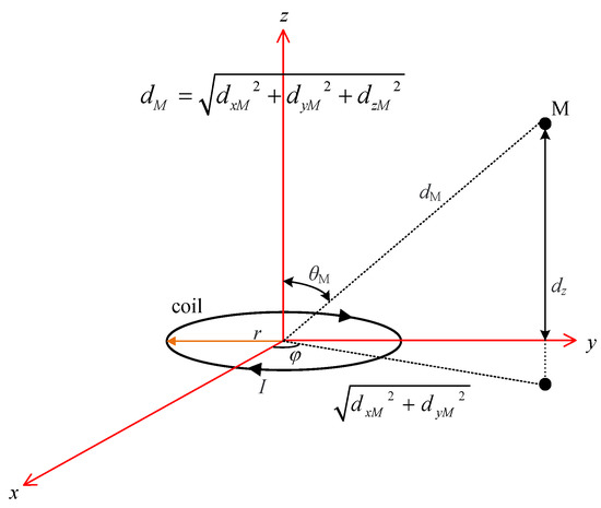
Figure 2.
Geometric model of the distance from the center of the coil to point M.
In Figure 2, the geometric model of the distance from the center of coil to point M is demonstrated, where the magnetic flux density at point M is a function of the coil radius, the current flowing through the coil, and the distance from the coil center to point M. The total magnetic flux density at point M is calculated by the following Equation (1) [29]:
where, , , , , .
Note that μ0 is the vacuum permeability, k is the wave number (2π/λ), λ is the wavelength (c/f), c is the speed of light (3 × 10⁸ m/s), f is the frequency, rN (N = 1, 2, …, n) is the coil radius, and N is the coil turn.
For the convenience of representation, the variable g is introduced here:
It is abundantly clear that g is a function that varies with the position of point M(x,y,z). Therefore, Equation (1) can be simplified as (3):
The geometric coil array of the transmitting, receiving, and shielding coils is depicted in Figure 3. It is apparent that the transmitting, receiving, and shielding coils are all coaxial coils. Thus, all coils have an identical distance for the x-axis and y-axis to point M. The distance of the x-y axis from point M in the Cartesian coordinate system can be calculated as √(x2 + y2).
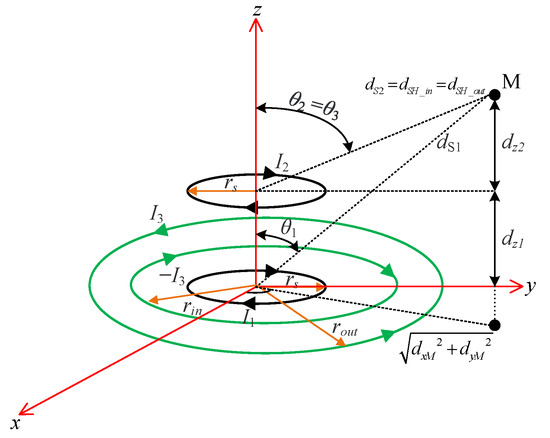
Figure 3.
Geometric coil array of transmitting, receiving, and shielding coils.
However, in the z-axis direction, the distances vary from coil to coil. Therefore, the distance to point M will differ with regard to the z-axis. The distance from the transmitting coil to the point M dS1 is then expressed by Equation (4).
Since the receiving coil and shielding coil are in the same plane, the distance from the receiving coil to point M has the same expression as the distance from the shielding coil to point M, as shown in Equation (5).
where dS2 is the distance from the receiving coil to point M; dSH_in and dSH_out are, respectively, the distance from the internal and external shielding coils to point M.
The total magnetic flux density BM at point M of the space is calculated by applying superposition as:
where B1, B2, B3_in, and B3_out are the magnetic flux density of the transmitting coil, receiving coil, and the internal and external shielding coils at point M, respectively, and these are calculated corresponding to the coil design through (1). Moreover, the shielding effectiveness (SE) is defined as follows:
3. Dynamic Shielding for WPT Systems with Double-Coil Active Shielding
3.1. Mathematical Analysis
The theory of double-coil active coil shielding is here addressed using a circuit approach. A WPT system with a series–series (SS) compensation topology [33] is modeled using an equivalent circuit as shown in Figure 4, with R1, R2, and R3 as the internal resistances; L1, L2, and L3 as self-inductances; C1, C2, and C3 as capacitances, and RL and RS as the resistive load and internal resistance of power transmitting. M12, M13, and M23 are the mutual inductances between coils, and subscript ‘1’, ‘2’, ‘3’ indicates the transmitting, receiving, and shielding coil, respectively. VS and VA are the power supply of the transmitting coil and the shielding coil, and I1, I2, and I3 are the current of the transmitting, receiving, and shielding coil, respectively. ω is the angular operating frequency.

Figure 4.
Equivalent circuit of WPT systems with double-coil active shielding.
It is worth mentioning that C3 can be neglected since there is enough active current injection to compensate for the EMF leakage.
Considering, for simplicity, a three-coil configuration (1—transmitting coil, 2—receiving coil, 3—active shielding coil), the total magnetic flux density at observation point M(x,y,z) in (6) can be simplified as:
where B3 is equal to the sum of B3_in and B3_out. Substituting Equation (3) into (11), there is:
It should be noted that the vectorial functions gk depend on the configuration of all coils, i.e., the transmitting, receiving, and active shielding coils. Therefore, the feeding of the active shielding coil depends not only on the EMF generated by the transmitting coil, but also on the EMF generated by the receiving coil.
Assuming that the shielding coil achieves an ideal SE, i.e., the total magnetic flux density BM measured at point M is zero, it yields:
The above Equation (13) can only be satisfied if point M lies on the surface of the plane loop with its normal axis unit vector na parallel to the direction of the sum of the incident fields:
However, in fact, for a given active coil structure, the shielding area cannot contain only one single point. Therefore, vector condition (14) cannot be completely satisfied in practice. Thus, a less restrictive but practical condition is introduced in the following.
Considering the diminishing of the main component of magnetic flux density under the condition that the active coil is properly scheduled and is planar, being parallel to the na, the compensation for the BM component in the direction na at a given point M is given by:
Expressing the current vector in (15) into (9), it yields:
To make the expression more concise, a new variable t is introduced:
Thus, Equation (16) is transformed into:
From this, the expression for the power supply of the active shielding coil is further derived:
With consideration of the losses incurred by the presence of double active shielding coils, the power transfer efficiency η of the system can be calculated as:
where P1 and P3 are the output power of the transmitting and active shielding coils, and P2 is the transferred power to load.
Variations in the position or current of the transmitting and receiving coils result in a corresponding change in the magnetic flux density of the WPT system. The dynamic shielding scheme proposed in this paper is to adjust the power supply VA in the active shielding coil according to the changes in coil position and current, allowing the excitation of the shielding coil to adapt to the changes in the EMF leakage of the WPT system.
3.2. Dynamic Shielding Scheme
As the application of EVs gradually spreads, different EVs have been presented with different structures and the distance between the vehicle chassis and the ground varies. This results in different strengths of EMF leakage when charging different EVs. If each EV needs to be designed with one active shielding mechanism, it would occupy much of the ground charging area.
Therefore, a double-coil dynamic shielding scheme based on active shielding technology is proposed in this paper. According to the power transmission distance of different EVs, the power supply of active shielding coils installed on the ground is adjusted, so that the EMF leakage of different EVs can be dynamically shielded. Regardless of the variation in the transmission distance of the WPT system, the EMF leakage level is always guaranteed to be within the safety range specified by the International Commission on Non-Ionizing Radiation Protection (ICNIRP) standards and guidelines.
With a constant charging power supply of the WPT system, the magnetic flux density varies with the transmission distance. A magnetic flux density detection module is used to detect the magnetic flux density at different transmission distances. This involves controlling the power supply VA of the active shielding coil, so high SE of the shielding system is maintained while adapting to changes in the transmission distance, resulting in dynamic and good shielding effectiveness.
A DC-AC inverter circuit with an adjustable duty cycle is added to the control loop so as to control the power supply of the active shielding coil. By adjusting VA, high SE for EMF leakage at varying distances is achieved in the active shielding system. The circuit design is shown in Figure 5.
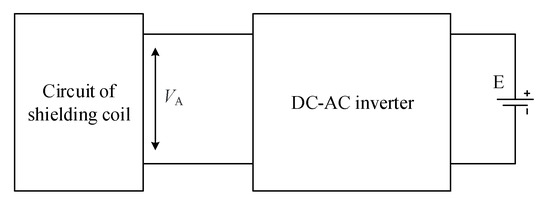
Figure 5.
Circuit design of active shielding system.
A DC-AC inverter circuit is a conversion device that transforms the DC input voltage and then outputs the AC voltage. It realizes the orderly closure of switching elements by controlling the driving voltage for on/off. Thus, the high DC voltage is converted to AC output voltage according to different circulation paths. It is controlled by pulse width modulation (PWM), which further changes the magnitude of the output voltage by shifting the trigger signal of the power electronic switch in the circuit.
When the power transmission distance changes, the EMF leakage also changes accordingly. As a result, the current flowing through the coil alters as well. In the DC-AC inverter circuit, the magnitude of output voltage VA is controlled by regulating the duty cycle of the PWM signal, so that the EMF leakage level is limited within ICNIRP.
The topologies often used in high-frequency inverter circuits are class E [34], double E [35], half-bridge, and full-bridge [36], and their circuit structures are shown in Figure 6.
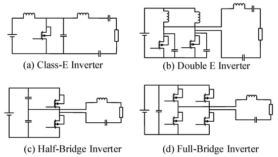
Figure 6.
Circuit structures of high-frequency inverters.
A class E inverter is a simple driving circuit with only one switching device, and it has the advantages of low switching losses and high conversion efficiency. However, the circuit is unlikely to provide high output power when the duty cycle is changed.
A double E inverter consists of two switching devices, each with half the input voltage of a class E inverter. In this case, it lowers the requirement of the DC power supply and switching devices and provides an improvement in power. However, it has a large current ripple in the input inductance and a high loss in the paralleled inductor, which reduces the efficiency of the inverter system.
A half-bridge inverter works through controlling two switching devices to alternate their conduction. It features a simple structure and requires fewer switching devices. However, the maximum AC output voltage is only half of the DC output, and the lower DC voltage utilization reduces the efficiency of the inverter system.
A full-bridge inverter consists of four bridge arms, which can be seen as a combination of two half-bridge inverters. At the same DC voltage and load, the output of a full-bridge inverter is two times that of a half-bridge inverter. Moreover, it has only one capacitor on the DC side, so there is no problem of voltage balance. It can be applied in a wider range and is more flexible to control.
In summary, a full-bridge inverter is more applicable to the WPT system in this work because of its simple structure, high voltage utilization, wide power range, flexible control, and no special requirements for the transmission distance. Therefore, the full-bridge inverter is selected in this work.
With the addition of a full-bridge inverter, it is possible to adjust VA by changing the duty cycle α of the pulse signal. In this way, the EMF leakage can be kept at a stable value while the transmission distance changes, which achieves the dynamic shielding effectiveness of the WPT system.
To further implement the dynamic shielding scheme, an MCU is added to the WPT system to guide the adjustment of α according to the detected magnetic flux density, and finally to enable the dynamic adjustment of VA. The algorithm flowchart of the proposed dynamic shielding scheme is presented in Figure 7.
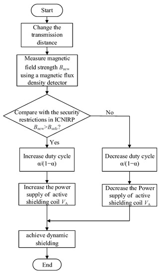
Figure 7.
Flowchart of proposed dynamic shielding scheme.
The dynamic shielding scheme allows the power supply of the active shielding coils to be adjusted so that EMF leakage is restricted to the safe level of ICNIRP. The ICNIRP reference levels for magnetic field exposure for WPT systems in different operating bands (1 Hz–100 kHz) are listed in Table 1. This work refers to the ICNIRP 2010 version [37].

Table 1.
Reference level of magnetic field exposure in the operating frequency range of 1 Hz–100 kHz in ICNIRP-2010.
When the operating frequency is fixed at a certain frequency band, a standard value of the referenced magnetic flux density is fixed. However, the transmission distance may not remain the same when charging different EVs. Therefore, the magnetic flux density will increase or decrease accordingly with the distance. As the transmission distance is shortened, the EMF leakage of the WPT system will increase accordingly. To ensure that the EMF leakage is within the safe range of ICNIRP, the adoption of the proposed dynamic shielding scheme can adjust VA accordingly. This causes the adjusted EMF leakage to drop below the reference level of ICNIRP 2010. While the transmission distance increases, the EMF leakage will become lower accordingly. From the perspective of energy saving and cost saving, VA should be reduced accordingly, which can help to ensure that the EMF leakage is within the safety limit of the ICNIRP 2010 standard and prevent excessive waste of resources.
The proposed dynamic shielding scheme is applicable to cases in which the transmission distance changes. It has a certain directive significance for future research on shielding technology for subsequent WPT systems.
4. Simulation and Experiments
4.1. Simulation Verification
For the verification of the proposed dynamic shielding scheme based on double-coil active shielding, a WPT system is built using ANSYS Maxwell simulation software. The WPT system operates at 85 kHz, and the safety limit of ICNIRP at this operating frequency is 27 μT. The simulated structure of the WPT coils is depicted in Figure 8. The transmitting and receiving coils have the same structure, both of which have an external radius of 100 mm; the number of turns N is 10, and the transmission distance Z2 is initialized to 100 mm. The double-coil active shielding structure consists of two half-loops with outer radius rout = 150 cm and inner radius rin = 130 cm.
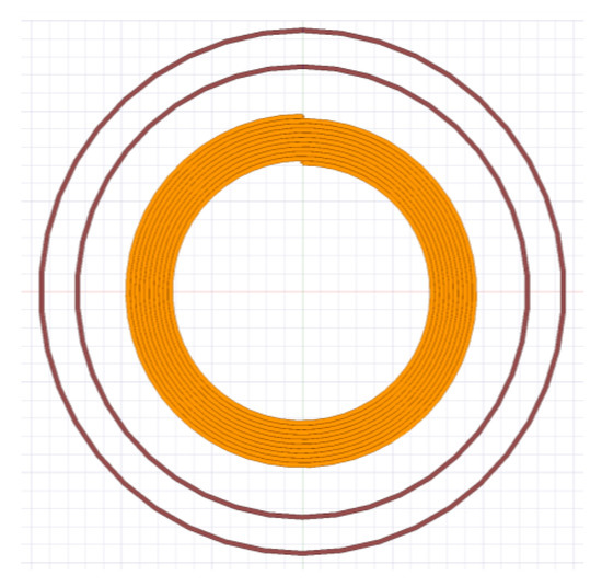
Figure 8.
Simulated structure of the WPT coils.
The circuit for the combined simulation by 3D Maxwell and Simplorer is illustrated in Figure 9. The transmitting power supply VS of the WPT system is set to 30 V. The internal resistance of power supply RS is 8 mΩ, and the resistance of the load resistor RL = 10 Ω. The other simulation parameters of the circuit are listed in Table 2. In addition, the variation of the power supply of the active shielding coil VA with the variation of the distance between the transmitting coil and receiving coil is given in the subsequent discussion. In addition, the changes in the power supply of active shielding coil VA with transmission distance are given in the subsequent discussion.
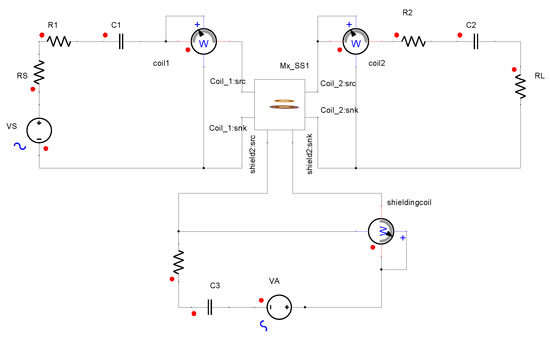
Figure 9.
Circuit for the combined simulation by 3D Maxwell and Simplorer.
Table 2.
Simulation parameters of WPT circuit.
In this paper, a dynamic shielding scheme is used to dynamically adjust the power supply of active shielding coils VA at transmission distances of 50 mm, 100 mm, and 150 mm. The EMF leakage of the WPT system is measured to ensure that its value is lower than the ICNIRP standard. The corresponding VA at different transmission distances is shown in Table 3.
Table 3.
VA at different transmission distances.
When the transmission distance is shortened, the magnetic flux density increases accordingly. Therefore, to meet the shielding requirements, the proposed dynamic shielding scheme is used to increase the VA to 41.61 V and to shield from excessive EMF leakage. When the distance increases, the magnetic flux density becomes smaller correspondingly. At this point, based on the consideration of saving resources and economic costs, VA is reduced to 20.06 V consequently, so that the EMF leakage is exactly within the safety limit of the ICNIRP standard, avoiding the unnecessary waste of resources.
The magnetic flux density distribution of the WPT system at different distances is displayed in in Figure 10 and Figure 11, demonstrating the EMF leakage with no shielding and double-coil active shielding. The comparison indicates that the magnetic flux density increases with the shortening of the transmission distance and decreases with the increase in transmission distance, when no shielding is available. Moreover, the EMF leakage outside the system is higher. However, with the addition of double-coil active shielding, the EMF leakage outside the WPT system is significantly reduced by adjusting VA, as illustrated in Figure 11.
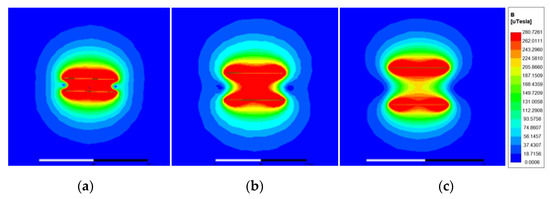
Figure 10.
The magnetic flux density distribution of WPT system with no shielding: (a) 50 mm; (b) 100 mm; (c) 150 mm.
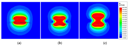
Figure 11.
The magnetic flux density distribution of WPT system with double-coil active shielding: (a) 50 mm; (b) 100 mm; (c) 150 mm.
To further prove the shielding effectiveness of the dynamic shielding scheme and the impact of double-coil active shielding on the power transfer efficiency of the WPT system, the shielding effectiveness SE and power transfer efficiency η at different transmission distances after adjusting VA are presented in Table 4.
Table 4.
SE and η at different transmission distances.
It can be seen that the SE of this dynamic shielding scheme reaches more than 69.4%. Moreover, with the increase in distance, the shielding effectiveness becomes more prominent. At 150 mm, it achieves 77.4% shielding effectiveness for EMF leakage in the WPT system. Furthermore, by comparing the η of the WPT system with double-coil active shielding and no shielding, it can be found that the addition of double-coil active shielding employed in the paper allows the power transfer efficiency to be essentially above 90%. Therefore, the involvement of this double-coil active shielding structure has not caused a significant impact on the transmission efficiency, and the degradation of the performance of the WPT system is mitigated. In summary, the effectiveness of the proposed dynamic shielding scheme is successfully verified.
4.2. Experimental Verification
In order to validate the correctness of the simulation results and the effectiveness and feasibility of the proposed dynamic shielding scheme, the circuit of the WPT system with double-coil active shielding is built in this paper. The structural framework is shown in Figure 12, and a physical diagram of the experimental setup is displayed in Figure 13. And the general specifications of measuring devices are listed in Appendix A. Two control experimental setups are used to better visualize the characteristics of this scheme. One group involves no shielding, and the other group involves double-coil active shielding but without the dynamic shielding scheme.
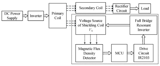
Figure 12.
The structural framework of WPT system with double-coil active shielding.
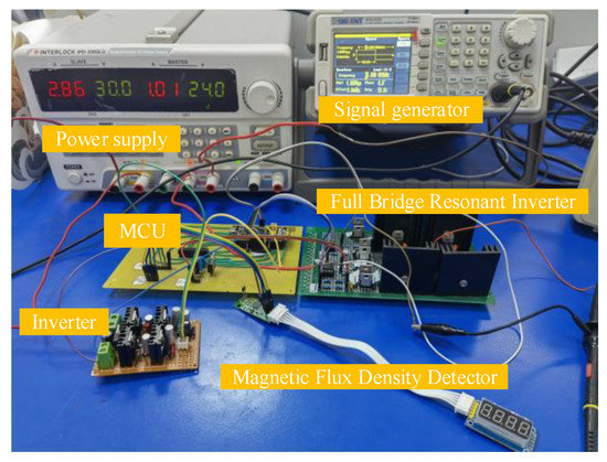
Figure 13.
Experimental setup.
It mainly consists of four parts: (1) a power control module composed of DC power supply and an inverter; (2) a power transmission module composed of three coils—a transmitting coil, half-loop shielding coils and receiving coil; (3) a dynamic shielding control module composed of a full-bridge inverter circuit, driving circuit, magnetic flux density detector, and micro-controller chip (MCU); (4) a load module composed of a rectifier circuit and load. The power supply for the WPT system is provided by a DC power supply, which, through the inverter, forms a high-frequency AC signal to the transmitting coil. The power is transmitted from the transmitting coil to the active shielding coils and receiving coil and then finally rectified and converted to provide power for the load.
This work focuses on the dynamic shielding control module consisting of a full-bridge inverter circuit, driver circuit, magnetic flux density detector, and MCU (the dashed block part in the Figure 12). The magnetic flux density of EMF leakage is detected by the magnetic flux density detector, and it is output to the MCU; then, the MCU applies the dynamic shielding scheme to calculate the corresponding duty cycle and connects the required control signal to IR2103 to drive the conduction of four MOSFETs in the full-bridge inverter. Thus, the power supply VA of the active shielding coils is controlled to realize the proposed dynamic shielding scheme.
Experiments are conducted by assigning different values to the transmission distance. The transmission distance is varied between 10 mm and 200 mm, and the variation step is set to 10 mm/step. The supply power VA is adjusted depending on the change in transmission distance. In the following, experimental results of this dynamic shielding scheme are analyzed.
The curve of VA variation with the transmission distance is shown in Figure 14. According to the ICNIRP standard, the magnetic flux density B is 27 μT. With the gradual increase in transmission distance, VA decreases accordingly. In the range of 0–50 mm, VA decreases sharply with the increase in transmission distance, and the decline is very apparent. It is related to the drastic magnetic flux density change in the near field of the WPT system. Within 50–150 mm, the decrease in VA becomes slightly less, and within 150–200 mm, the change in VA tends towards a stable value, which is related to the limited transmission distance of WPT technology.
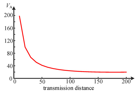
Figure 14.
The VA variation with transmission distance.
According to the guidance in Figure 14, VA is adjusted so that the magnetic flux density reaches below 27 μT at different transmission distances. The variation curves of magnetic flux density at different transmission distances are given in Figure 15. Blue indicates no shielding, red represents the case with double-coil active shielding but without the dynamic shielding scheme (here VA = 24 V and the initial transmission distance is 100 mm), and yellow represents the case with double-coil active shielding and with the dynamic shielding scheme to adjust VA. Lines indicate calculated values, and dots indicate measured values.
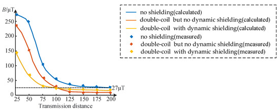
Figure 15.
Curves of magnetic flux density at different transmission distances.
It can be seen from the three curves in Figure 15 that the measured and calculated values are in general agreement. Without shielding, the magnetic flux density within 10–163 mm is higher than the safety limit of 27 μT, and only in the range of 163–200 mm is it below the safety standard. When double-coil active shielding is used without the dynamic shielding scheme, the magnetic flux density is significantly higher than 27 μT at a distance less than the initial transmission distance of 100 mm. The greater the distance, the greater the flux density. Obviously, at reduced distances, the initial supply power VA is not sufficient to shield the EMF leakage of the WPT system. Moreover, at a distance greater than the initial transmission distance, the magnetic flux density becomes gradually lower than the safety limit, when no corresponding adjustment of VA will also result in a waste of resources. When adopting double-coil active shielding and applying the dynamic shielding scheme to adjust VA, the EMF leakage can be basically kept below the safety limit of 27 μT regardless of the increase in or shortening of the transmission distance. It avoids excessive power waste when the distance increases and solves the problem of excessive EMF exposure to human safety.
A comparison of the shielding effectiveness SE with and without the dynamic shielding scheme for different transmission distances is shown in Figure 16. Measured and calculated values remain largely consistent. Without the dynamic shielding scheme, SE becomes progressively larger with increasing distance. This means that the closer one approaches the coil, the less EMF leakage is shielded. The higher the level of EMF exposure, the greater the risk to humans. This is due to the fact that VA is not regulated accordingly. When the distance decreases, the magnetic flux density increases, and the original VA is no longer enough to shield a sufficient amount of EMF leakage. On the other hand, with the dynamic shielding scheme, SE increases when the transmission distance is smaller and decreases slightly when the transmission distance becomes longer. The closer to the transmitting coil, the higher the magnetic flux density of EMF leakage, when a higher shielding effectiveness SE is required to bring the EMF leakage level down to within the safe range. The results show that this method is consistent with the limits of EMF exposure requirements and validate the effectiveness of the dynamic shielding scheme.
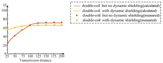
Figure 16.
SE for different transmission distances with and without dynamic shielding scheme.
To further confirm the feasibility of this dynamic shielding scheme, the power transmission efficiency η of the WPT system is investigated. Figure 17 shows the variation curves of η at different transmission distances, where blue denotes no shielding and yellow denotes double-coil active shielding. It is clear that, although slightly fluctuating, the measured values match well with the calculated values. The η with double-coil active shielding is slightly reduced compared with that with no shielding, but the reduction is not significant and is approximately 3.1%. It is related to the introduction of the shielding system. It can be found that the addition of this double-coil active shielding structure achieves good shielding effectiveness against EMF leakage at the same time, without causing a significant sacrifice in power transmission efficiency. This means that the application of the double-coil dynamic shielding scheme can not only avoid the waste of power but also reduce the degrading influence of the shielding device on the transmission performance of the WPT system; thus, its feasibility is verified.
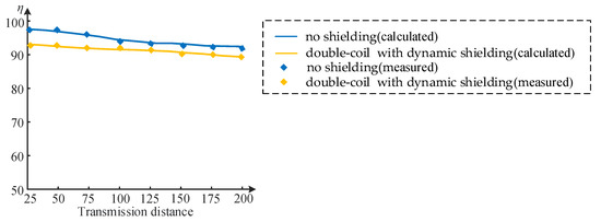
Figure 17.
Curves of η at different transmission distances.
5. Conclusions
Given that different transmission distances lead to different degrees of EMF leakage, a double-coil dynamic shielding scheme based on active shielding technology is proposed in this paper. The active shielding coils adopt two half-loop structures and are set on the outside of the transmitting coil. The supply power of the active shielding coils installed on the ground is adjusted according to different transmission distances to achieve dynamic shielding of EMF leakage with different EVs. The WPT system with the proposed double-coil dynamic shielding scheme is modeled, simulated, experimented, and compared with other WPT systems.
The simulation and experimental results show that the proposed double-coil dynamic shielding scheme can shield approximately 77.4% of the EMF leakage and maintain high shielding effectiveness as the transmission distance varies. Furthermore, the application of the double-coil dynamic shielding scheme essentially has no effect on the power transmission efficiency. Therefore, the adaptability, effectiveness, and feasibility of the double-coil dynamic shielding scheme for WPT systems with different transmission distances are verified.
EVs currently available in the market have different structures, and the distances between their vehicle chassis and the ground are bound to be different. When the transmitting coil is fixed to the ground in the WPT system, EVs with different chassis heights signify different transmission distances. The proposed double-coil dynamic shielding scheme can shield the EMF leakage as the transmission distance changes, avoiding the repeated design of the shielding system. The proposed scheme is also generally applicable to other cases where the position of the transmitting coil is fixed but the distance of the receiving coil changes. Thus far, the scheme involves a large amount of analytical calculations, and it is hoped that a more concise method can be sought in future research.
Author Contributions
Conceptualization, Y.L. and Z.C.; methodology, Y.L.; software, Y.L.; validation, Y.L.; formal analysis, Y.L.; investigation, Y.L.; resources, Y.L.; data curation, Y.L.; writing—original draft preparation, Y.L.; writing—review and editing, Y.L.; visualization, Y.L.; supervision, S.Z.; project administration, Z.C.; funding acquisition, Z.C. and S.Z. All authors have read and agreed to the published version of the manuscript.
Funding
This research was funded by National Natural Science Foundation of China, grant number 61903272 and 61873180.
Institutional Review Board Statement
Not applicable.
Informed Consent Statement
Not applicable.
Conflicts of Interest
The authors declare no conflict of interest.
Nomenclature
| WPT | wireless power transfer |
| EV | electric vehicle |
| EMF | electromagnetic field |
| ICNIRP | International Commission on Non-Ionizing Radiation Protection |
| rin | inner radius of half-loop |
| rout | outer radius of half-loop |
| rs | radius of transmitting coil |
| BM | total magnetic flux density at point M |
| dS1 | distance from the transmitting coil to the point M |
| dS2 | distance from the receiving coil to point M |
| B1 | magnetic flux density of transmitting coil |
| B2 | magnetic flux density of receiving coil |
| B3_in | magnetic flux density of the internal shielding coils at point M |
| B3_out | magnetic flux density of the external shielding coils at point M |
| SE | shielding effectiveness |
| R1,2,3 | internal resistances of the transmitting, receiving, and shielding coils |
| L1,2,3 | self-inductances of the transmitting, receiving, and shielding coils |
| C1,2,3 | capacitances of the transmitting, receiving, and shielding coils |
| RL | resistive load |
| RS | internal resistance of power supply |
| M12 | mutual inductances between transmitting and receiving coils |
| M13 | mutual inductances between transmitting and shielding coils |
| M23 | mutual inductances between receiving and shielding coils |
| I1,2,3 | current of transmitting, receiving, and shielding coils |
| ω | angular operating frequency |
| VS | power supply of transmitting coil |
| VA | power supply of shielding coil |
| P1,2,3 | output power of transmitting, receiving, and active shielding coils |
| PWM | pulse width modulation |
| α | duty cycle |
| N | number of turns |
| MCU | micro-controller chip |
| η | power transfer efficiency |
Appendix A
Table A1.
General specifications of measuring devices used in the WPT experiment.
Table A1.
General specifications of measuring devices used in the WPT experiment.
| Devices | Product Model | Operating Parameters |
|---|---|---|
| Power Supply | IPD-3303LU | 0~32 V |
| Magnetic Flux Density Detector | SS49E | −1000~1000 Gs |
| Signal Generator | SDG830 | 1 μHz~30 MHz |
| Drive Circuit | IR2103 | 10~20 V |
| MCU | STM32F103C8T6 | 2~3.6V |
| MOSFET | IRF640 | −20~20 V |
Appendix B
Table A2.
Features of various shielding technologies in WPT.
Table A2.
Features of various shielding technologies in WPT.
| Shielding Technology | Advantages | Disadvantages |
|---|---|---|
| Passive Shielding | simple operation, easy implementation | large volume, high space occupation, increased loss |
| Resonant Reactive Current Loop | small additional volume, simple structure | lower shielding effectiveness |
| Active Shielding | high shielding effectiveness, small additional volume | complicated calculations |
References
- Triviño, A.; Gonzalez-Gonzalez, J.; Castilla, M. Review on Control Techniques for EV Bidirectional Wireless Chargers. Electronics 2021, 10, 1905. [Google Scholar] [CrossRef]
- Arif, S.; Lie, T.; Seet, B.; Ayyadi, S.; Jensen, K. Review of Electric Vehicle Technologies, Charging Methods, Standards and Optimization Techniques. Electronics 2021, 10, 1910. [Google Scholar] [CrossRef]
- Sanguesa, J.; Torres-Sanz, V.; Garrido, P.; Martinez, F.; Marquez-Barja, J. A Review on Electric Vehicles: Technologies and Challenges. Smart Cities 2021, 4, 372–404. [Google Scholar] [CrossRef]
- Li, S.; Mi, C.C. Wireless power transfer for electric vehicle applications. IEEE J. Emerg. Sel. Top. Power Electron. 2014, 3, 4–17. [Google Scholar]
- Bertoluzzo, M.; Di Monaco, M.; Buja, G.; Tomasso, G.; Genovese, A. Comprehensive Development of Dynamic Wireless Power Transfer System for Electric Vehicle. Electronics 2020, 9, 1045. [Google Scholar] [CrossRef]
- Colussi, J.; La Ganga, A.; Re, R.; Guglielmi, P.; Armando, E. 100 kW Three-Phase Wireless Charger for EV: Experimental Val-idation Adopting Opposition Method. Energies 2021, 14, 2113. [Google Scholar] [CrossRef]
- Chen, K.; Cheng, K.; Yang, Y.; Pan, J. Stability Improvement of Dynamic EV Wireless Charging System with Receiver-Side Control Considering Coupling Disturbance. Electronics 2021, 10, 1639. [Google Scholar] [CrossRef]
- Zhu, Q.; Zhang, Y.; Guo, Y.; Liao, C.; Wang, L.; Wang, L. Null-Coupled Electromagnetic Field Cancelling Coil for Wireless Power Transfer System. IEEE Trans. Transp. Electrif. 2016, 3, 464–473. [Google Scholar] [CrossRef]
- Mohamed, A.; Marim, A.A.; Mohammed, O. Magnetic Design Considerations of Bidirectional Inductive Wireless Power Transfer System for EV Applications. IEEE Trans. Magn. 2017, 53, 1–5. [Google Scholar] [CrossRef]
- Do, C.Y.; Park, E.Y. Impact investigations and characteristics by strong electromagnetic field of wireless power charging system for electric vehicle under air and water exposure indexes. IEEE Trans. Appl. Supercond. 2018, 28, 1–5. [Google Scholar]
- Yamazaki, K.; Taki, M.; Ohkubo, C. Safety assessment of human exposure to intermediate frequency electromagnetic fields. Electr. Eng. Jap. 2016, 197, 3–11. [Google Scholar] [CrossRef]
- Campi, T.; Cruciani, S.; De Santis,, V. EMC and EMF safety issues in wireless charging system for an electric vehicle (EV). In Proceedings of the 2017 International Conference of Electrical and Electronic Technologies for Automotive, Turin, Italy, 27 July 2017; IEEE: Piscataway, NJ, USA, 2017; pp. 1–4. [Google Scholar]
- Miyakoshi, J.; Tonomura, H.; Koyama, S.; Narita, E.; Shinohara, N. Effects of Exposure to 5.8 GHz Electromagnetic Field on Micronucleus Formation, DNA Strand Breaks, and Heat Shock Protein Expressions in Cells Derived from Human Eye. IEEE Trans. NanoBiosci. 2019, 18, 257–260. [Google Scholar] [CrossRef]
- Asa, E.; Mohammad, M.; Onar, O.C.; Pries, J.; Galigekere, V.; Su, G.-J. Review of Safety and Exposure Limits of Electromagnetic Fields (EMF) in Wireless Electric Vehicle Charging (WEVC) Applications. In Proceedings of the 2020 IEEE Transportation Electrification Conference & Expo (ITEC), Chicago, IL, USA, 23–26 June 2020; pp. 17–24. [Google Scholar] [CrossRef]
- Shin, Y.; Park, J.; Kim, H.; Woo, S.; Park, B.; Huh, S.; Lee, C.; Ahn, S. Design Considerations for Adding Series Inductors to Reduce Electromagnetic Field Interference in an Over-Coupled WPT System. Energies 2021, 14, 2791. [Google Scholar] [CrossRef]
- Tang, L.-C.; Jeng, S.-L.; Chang, E.-Y.; Chieng, W.-H. Variable-Frequency Pulse Width Modulation Circuits for Resonant Wireless Power Transfer. Energies 2021, 14, 3656. [Google Scholar] [CrossRef]
- Feliziani, M.; Cruciani, S.; Campi, T.; Maradei, F. Near Field Shielding of a Wireless Power Transfer (WPT) Current Coil. Prog. Electromagn. Res. C 2017, 77, 39–48. [Google Scholar] [CrossRef][Green Version]
- Lee, S.; Jeong, S.; Hong, S.; Sim, B.; Kim, J. Design and Analysis of EMI Shielding Method using Intermediate Coil for Train WPT System. In Proceedings of the 2018 IEEE Wireless Power Transfer Conference (WPTC), Montreal, QC, Canada, 3–7 June 2018; pp. 1–4. [Google Scholar] [CrossRef]
- Zhang, B.; Carlson, R.B.; Galigekere, V.P.; Onar, O.C.; Pries, J.L. Electromagnetic Shielding Design for 200 kW Stationary Wireless Charging of Light-Duty EV. In Proceedings of the IEEE Energy Conversion Congress and Exposition (ECCE), Detroit, MI, USA, 1–15 October 2020; pp. 5185–5192. [Google Scholar] [CrossRef]
- Kim, J.; Kim, J.; Kong, S. Coil design and shielding methods for a magnetic resonant wireless power transfer system. Proc. IEEE 2013, 101, 1332–1342. [Google Scholar] [CrossRef]
- Tan, L.; Elnail, K.E.I.; Ju, M.; Huang, X. Comparative Analysis and Design of the Shielding Techniques in WPT Systems for Charging EVs. Energies 2019, 12, 2115. [Google Scholar] [CrossRef]
- Mohammad, M.; Wodajo, E.T.; Choi, S.; Elbuluk, M.E. Modeling and Design of Passive Shield to Limit EMF Emission and to Minimize Shield Loss in Unipolar Wireless Charging System for EV. IEEE Trans. Power Electron. 2019, 34, 12235–12245. [Google Scholar] [CrossRef]
- Wen, F.; Huang, X. Optimal Magnetic Field Shielding Method by Metallic Sheets in Wireless Power Transfer System. Energies 2016, 9, 733. [Google Scholar] [CrossRef]
- Li, J.; Huang, X.; Chen, C.; Tan, L.; Wang, W.; Guo, J. Effect of metal shielding on a wireless power transfer system. AIP Adv. 2017, 7, 056675. [Google Scholar] [CrossRef]
- Kim, S.; Park, H.-H.; Kim, J.; Kim, J.; Ahn, S. Design and Analysis of a Resonant Reactive Shield for a Wireless Power Electric Vehicle. IEEE Trans. Microw. Theory Tech. 2014, 62, 1057–1066. [Google Scholar] [CrossRef]
- Park, J.; Kim, D.; Hwang, K. A resonant reactive shielding for planar wireless power transfer system in smartphone applica-tion. IEEE Trans. Electromagn. Compat. 2017, 59, 695–703. [Google Scholar] [CrossRef]
- Nie, Y.; Jiao, C.; Fan, Y. Active Shielding Design of Patrol Robot Wireless Charging System. In Proceedings of the 2019 IEEE 3rd International Electrical and Energy Conference (CIEEC), Beijing, China, 7–9 September 2019; IEEE: Piscataway, NJ, USA, 2019; pp. 2003–2007. [Google Scholar]
- Campi, T.; Cruciani, S.; Maradei, F.; Feliziani, M. Active Coil System for Magnetic Field Reduction in an Automotive Wireless Power Transfer System. In Proceedings of the 2019 IEEE International Symposium on Electromagnetic Compatibility, Signal & Power Integrity (EMC + SIPI), New Orleans, LA, USA, 22–26 July 2019; pp. 189–192. [Google Scholar] [CrossRef]
- Kim, J.; Ahn, J.; Huh, S.; Kim, K.; Ahn, S. A Coil Design and Control Method of Independent Active Shielding System for Leakage Magnetic Field Reduction of Wireless UAV Charger. IEICE Trans. Commun. 2020, 103, 889–898. [Google Scholar] [CrossRef]
- Choi, S.Y.; Gu, B.W.; Lee, S.W.; Lee, W.Y.; Huh, J.; Rim, C.T. Generalized Active EMF Cancel Methods for Wireless Electric Vehicles. IEEE Trans. Power Electron. 2013, 29, 5770–5783. [Google Scholar] [CrossRef]
- Triviño, A.; González-González, J.; Aguado, J. Wireless Power Transfer Technologies Applied to Electric Vehicles: A Review. Energies 2021, 14, 1547. [Google Scholar] [CrossRef]
- De Santis, V.; Giaccone, L.; Freschi, F. Chassis Influence on the Exposure Assessment of a Compact EV during WPT Recharging Operations. Magnetochemistry 2021, 7, 25. [Google Scholar] [CrossRef]
- Kim, D.-H.; Kim, M.-S.; Kim, H.-J. Frequency-Tracking Algorithm Based on SOGI-FLL for Wireless Power Transfer System to Operate ZPA Region. Electronics 2020, 9, 1303. [Google Scholar] [CrossRef]
- Aldhaher, S.; Luk, P.; Whidborne, J. Tuning Class E Inverters Applied in Inductive Links Using Saturable Reactors. IEEE Trans. Power Electron. 2013, 29, 2969–2978. [Google Scholar] [CrossRef]
- Uddin, M.K.; Ramasamy, G.; Mekhilef, S.; Ramar, K.; Lau, Y.-C. A review on high frequency resonant inverter technologies for wireless power transfer using magnetic resonance coupling. In Proceedings of the 2014 IEEE Conference on Energy Conversion (CENCON), Johor Bahru, Malaysia, 13–14 October 2014; pp. 412–417. [Google Scholar] [CrossRef]
- Asl, E.S.; Babaei, E.; Sabahi, M.; Nozadian, M.H.B.; Cecati, C. New Half-Bridge and Full-Bridge Topologies for a Switched-Boost Inverter with Continuous Input Current. IEEE Trans. Ind. Electron. 2017, 65, 3188–3197. [Google Scholar] [CrossRef]
- Vassilev, A.; Ferber, A.; Wehrmann, C.; Pinaud, O.; Schilling, M.; Ruddle, A.R. Magnetic Field Exposure Assessment in Electric Vehicles. IEEE Trans. Electromagn. Compat. 2014, 57, 35–43. [Google Scholar] [CrossRef]


Publisher’s Note: MDPI stays neutral with regard to jurisdictional claims in published maps and institutional affiliations. |
© 2021 by the authors. Licensee MDPI, Basel, Switzerland. This article is an open access article distributed under the terms and conditions of the Creative Commons Attribution (CC BY) license (https://creativecommons.org/licenses/by/4.0/).