3.1. Mathematical Analysis
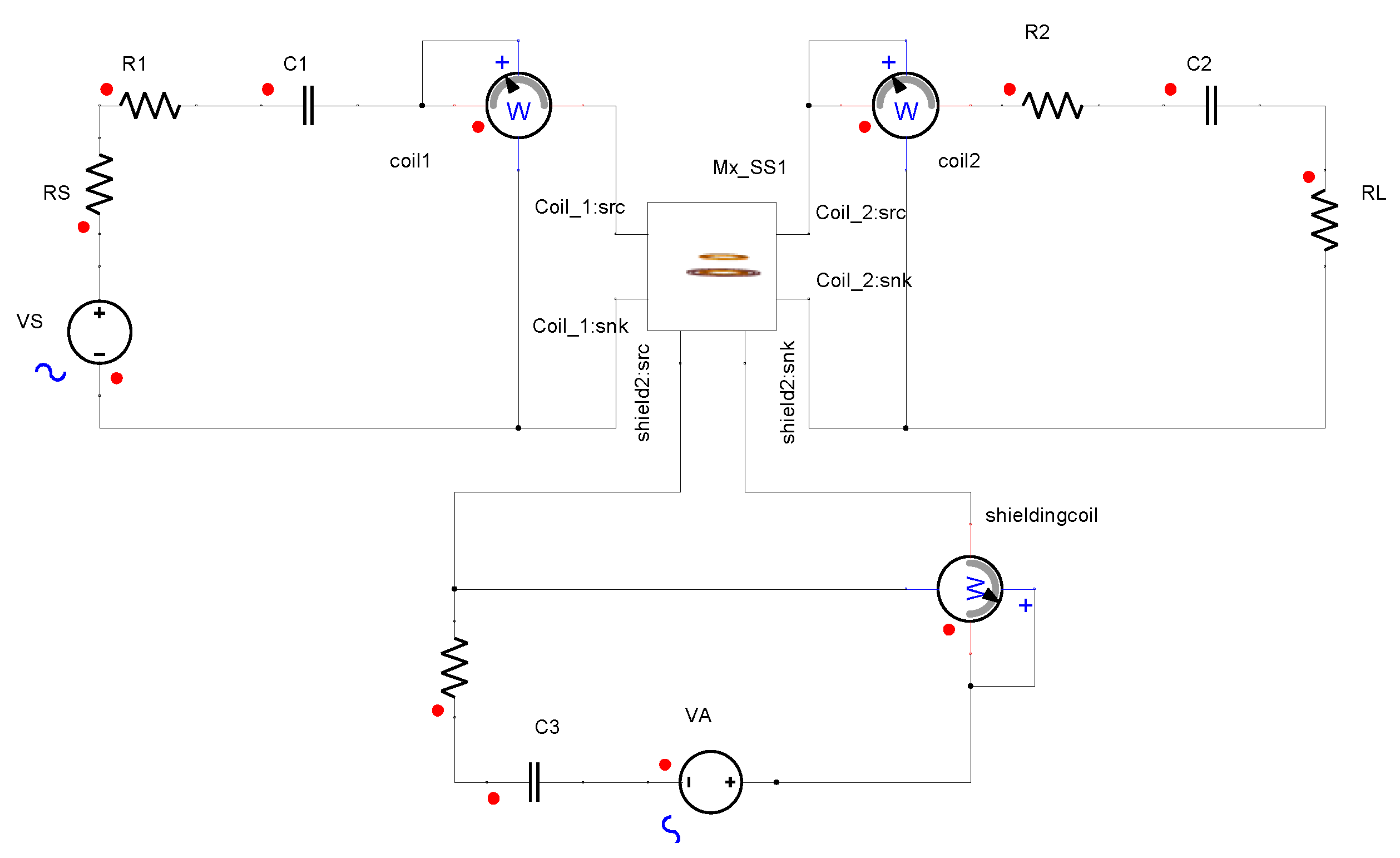
The theory of double-coil active coil shielding is here addressed using a circuit approach. A WPT system with a series–series (SS) compensation topology [
33] is modeled using an equivalent circuit as shown in
Figure 4, with
R1,
R2, and
R3 as the internal resistances;
L1,
L2, and
L3 as self-inductances;
C1,
C2, and
C3 as capacitances, and
RL and
RS as the resistive load and internal resistance of power transmitting.
M12,
M13, and
M23 are the mutual inductances between coils, and subscript ‘1’, ‘2’, ‘3’ indicates the transmitting, receiving, and shielding coil, respectively.
VS and
VA are the power supply of the transmitting coil and the shielding coil, and
I1,
I2, and
I3 are the current of the transmitting, receiving, and shielding coil, respectively.
ω is the angular operating frequency.
The equivalent circuit in
Figure 4 can be calculated as follows:
It is worth mentioning that C3 can be neglected since there is enough active current injection to compensate for the EMF leakage.
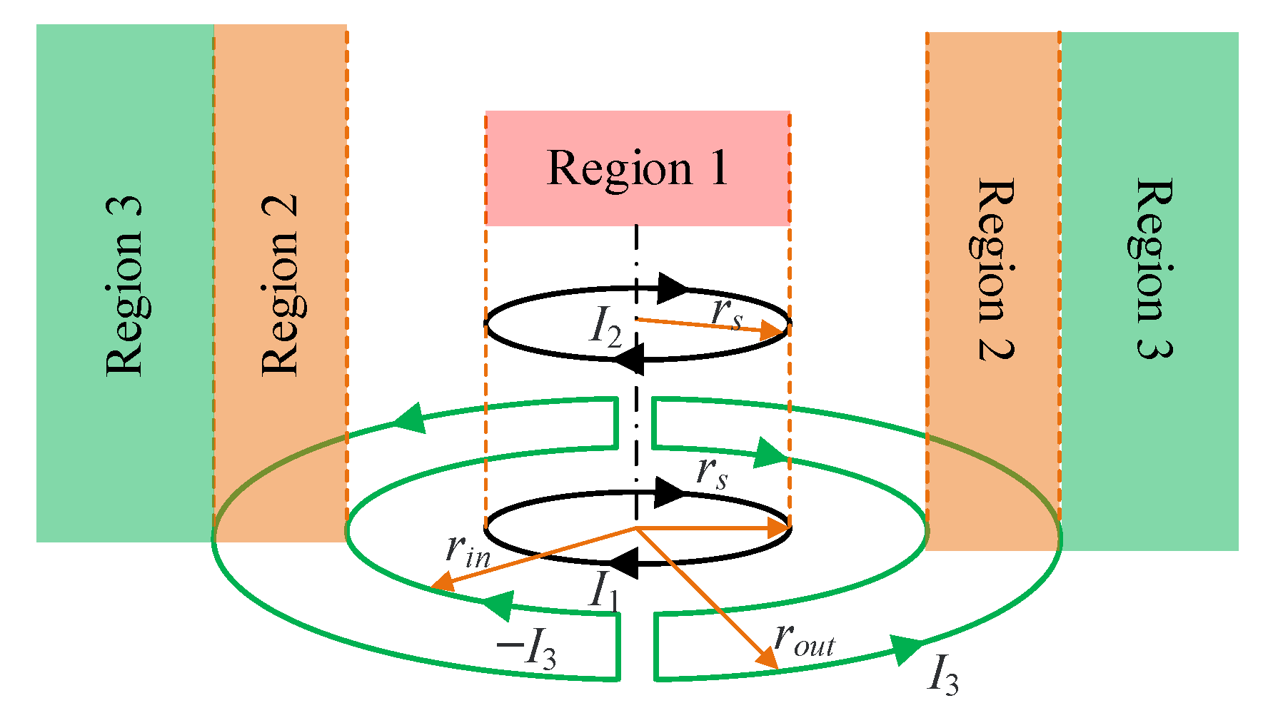
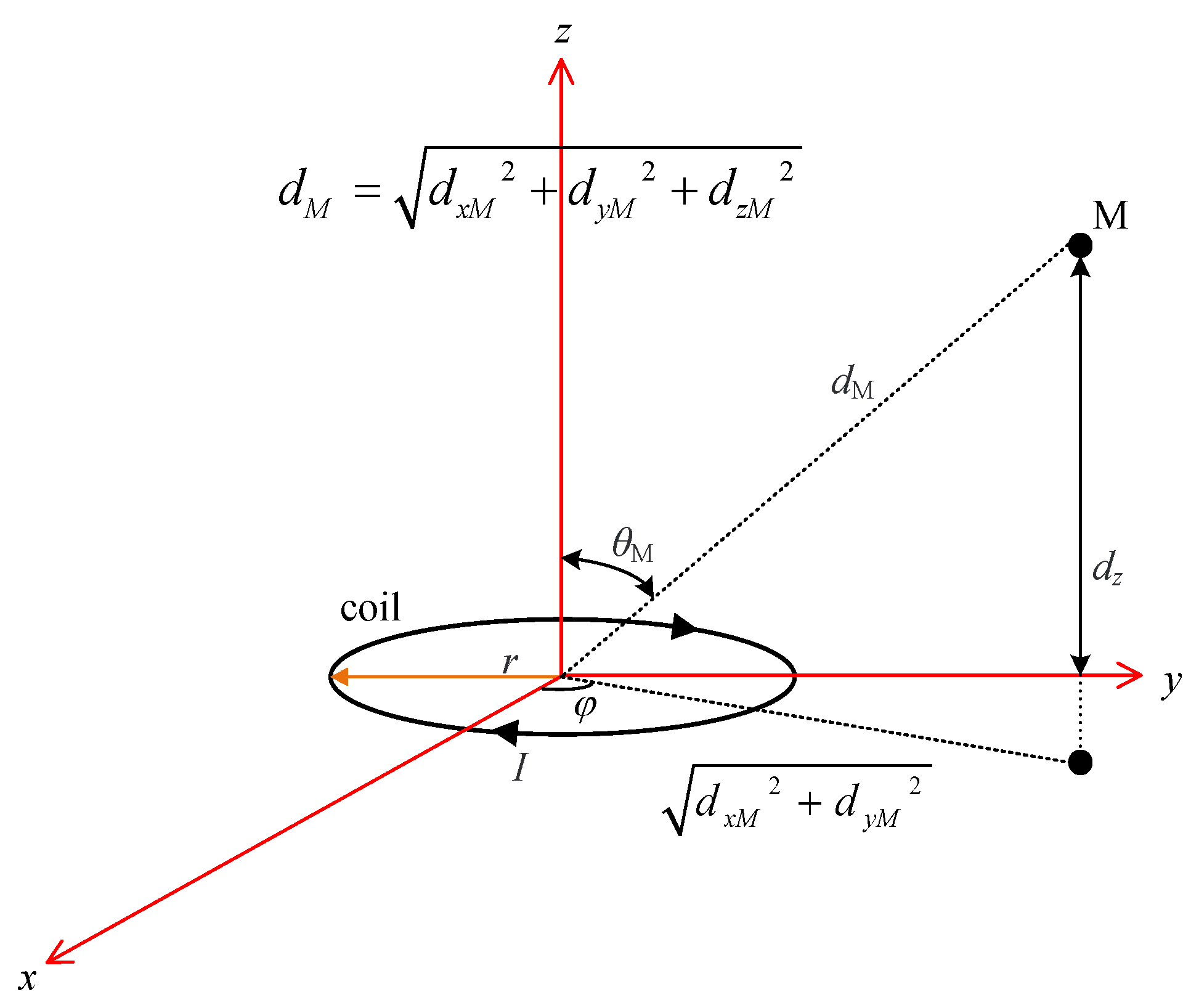
Considering, for simplicity, a three-coil configuration (1—transmitting coil, 2—receiving coil, 3—active shielding coil), the total magnetic flux density at observation point M(
x,
y,
z) in (6) can be simplified as:
where
B3 is equal to the sum of
B3_in and
B3_out. Substituting Equation (3) into (11), there is:
It should be noted that the vectorial functions gk depend on the configuration of all coils, i.e., the transmitting, receiving, and active shielding coils. Therefore, the feeding of the active shielding coil depends not only on the EMF generated by the transmitting coil, but also on the EMF generated by the receiving coil.
Assuming that the shielding coil achieves an ideal SE, i.e., the total magnetic flux density B
M measured at point M is zero, it yields:
The above Equation (13) can only be satisfied if point M lies on the surface of the plane loop with its normal axis unit vector n
a parallel to the direction of the sum of the incident fields:
However, in fact, for a given active coil structure, the shielding area cannot contain only one single point. Therefore, vector condition (14) cannot be completely satisfied in practice. Thus, a less restrictive but practical condition is introduced in the following.
Considering the diminishing of the main component of magnetic flux density under the condition that the active coil is properly scheduled and is planar, being parallel to the
na, the compensation for the
BM component in the direction
na at a given point M is given by:
Expressing the current vector in (15) into (9), it yields:
To make the expression more concise, a new variable t is introduced:
Thus, Equation (16) is transformed into:
From this, the expression for the power supply of the active shielding coil is further derived:
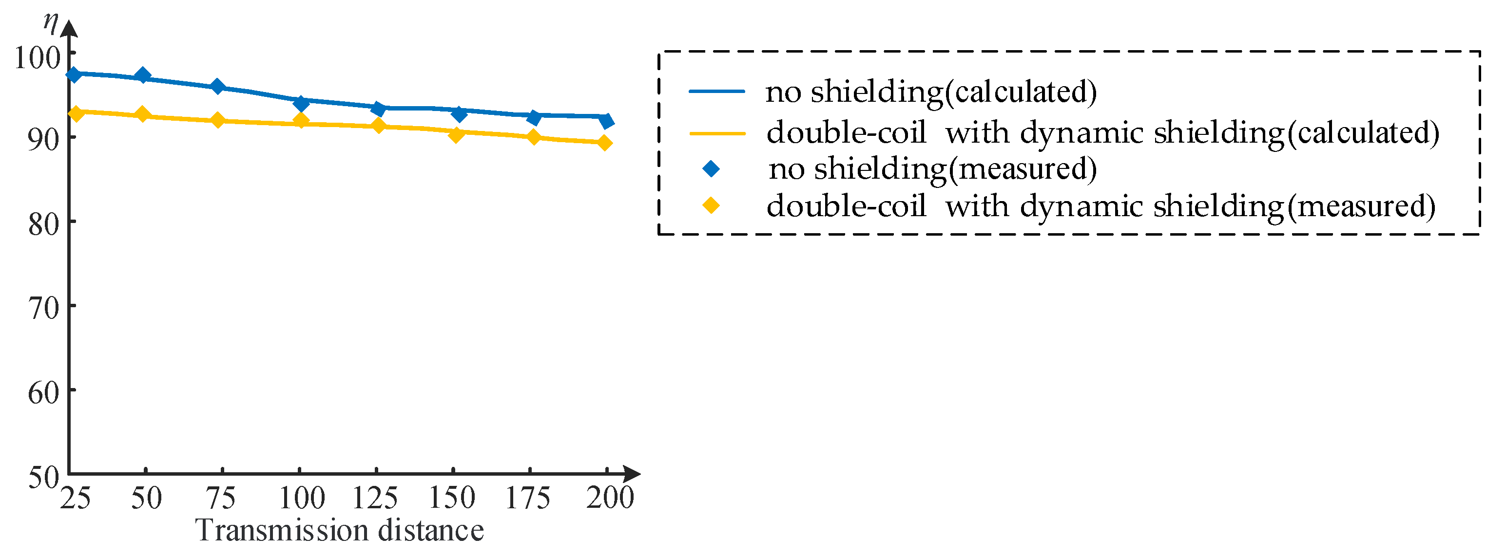
With consideration of the losses incurred by the presence of double active shielding coils, the power transfer efficiency
η of the system can be calculated as:
where
P1 and
P3 are the output power of the transmitting and active shielding coils, and
P2 is the transferred power to load.
Variations in the position or current of the transmitting and receiving coils result in a corresponding change in the magnetic flux density of the WPT system. The dynamic shielding scheme proposed in this paper is to adjust the power supply VA in the active shielding coil according to the changes in coil position and current, allowing the excitation of the shielding coil to adapt to the changes in the EMF leakage of the WPT system.
3.2. Dynamic Shielding Scheme
As the application of EVs gradually spreads, different EVs have been presented with different structures and the distance between the vehicle chassis and the ground varies. This results in different strengths of EMF leakage when charging different EVs. If each EV needs to be designed with one active shielding mechanism, it would occupy much of the ground charging area.
Therefore, a double-coil dynamic shielding scheme based on active shielding technology is proposed in this paper. According to the power transmission distance of different EVs, the power supply of active shielding coils installed on the ground is adjusted, so that the EMF leakage of different EVs can be dynamically shielded. Regardless of the variation in the transmission distance of the WPT system, the EMF leakage level is always guaranteed to be within the safety range specified by the International Commission on Non-Ionizing Radiation Protection (ICNIRP) standards and guidelines.
With a constant charging power supply of the WPT system, the magnetic flux density varies with the transmission distance. A magnetic flux density detection module is used to detect the magnetic flux density at different transmission distances. This involves controlling the power supply VA of the active shielding coil, so high SE of the shielding system is maintained while adapting to changes in the transmission distance, resulting in dynamic and good shielding effectiveness.
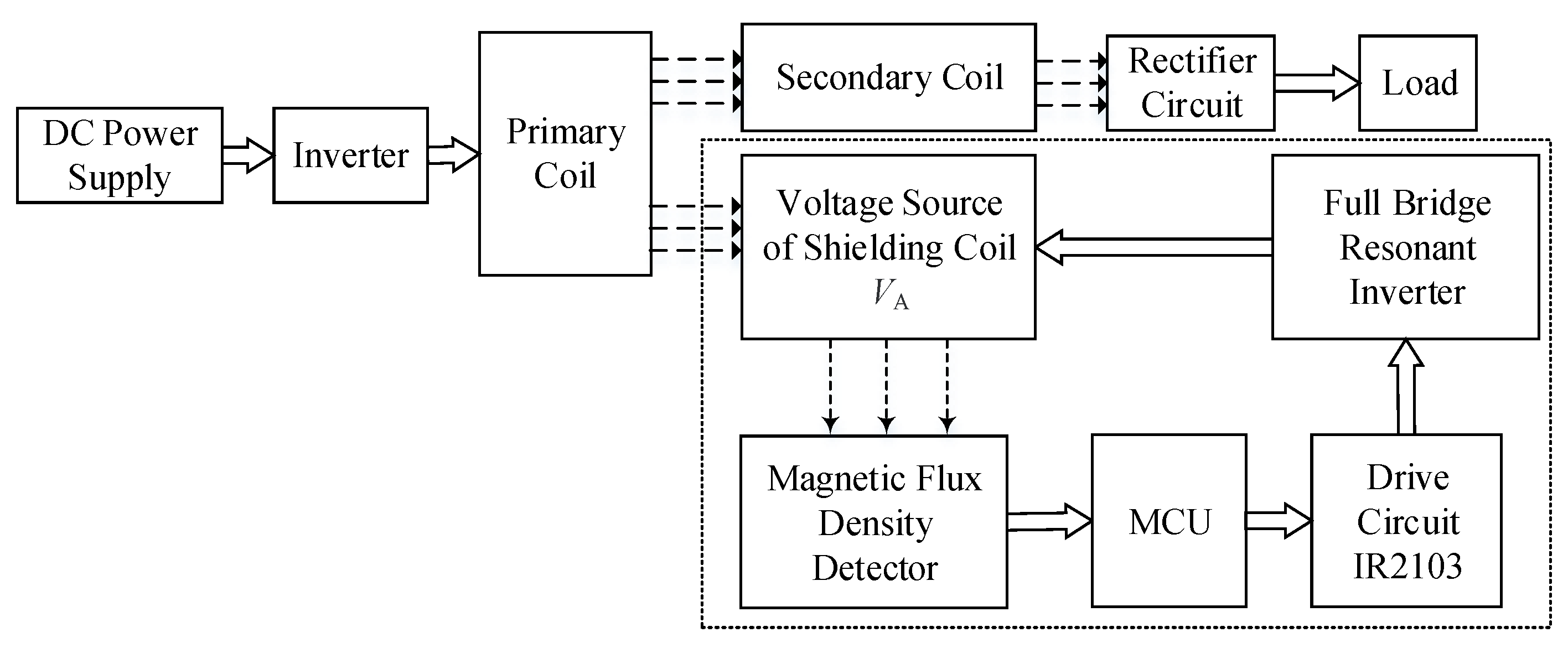
A DC-AC inverter circuit with an adjustable duty cycle is added to the control loop so as to control the power supply of the active shielding coil. By adjusting
VA, high
SE for EMF leakage at varying distances is achieved in the active shielding system. The circuit design is shown in
Figure 5.
A DC-AC inverter circuit is a conversion device that transforms the DC input voltage and then outputs the AC voltage. It realizes the orderly closure of switching elements by controlling the driving voltage for on/off. Thus, the high DC voltage is converted to AC output voltage according to different circulation paths. It is controlled by pulse width modulation (PWM), which further changes the magnitude of the output voltage by shifting the trigger signal of the power electronic switch in the circuit.
When the power transmission distance changes, the EMF leakage also changes accordingly. As a result, the current flowing through the coil alters as well. In the DC-AC inverter circuit, the magnitude of output voltage VA is controlled by regulating the duty cycle of the PWM signal, so that the EMF leakage level is limited within ICNIRP.
The topologies often used in high-frequency inverter circuits are class E [
34], double E [
35], half-bridge, and full-bridge [
36], and their circuit structures are shown in
Figure 6.
A class E inverter is a simple driving circuit with only one switching device, and it has the advantages of low switching losses and high conversion efficiency. However, the circuit is unlikely to provide high output power when the duty cycle is changed.
A double E inverter consists of two switching devices, each with half the input voltage of a class E inverter. In this case, it lowers the requirement of the DC power supply and switching devices and provides an improvement in power. However, it has a large current ripple in the input inductance and a high loss in the paralleled inductor, which reduces the efficiency of the inverter system.
A half-bridge inverter works through controlling two switching devices to alternate their conduction. It features a simple structure and requires fewer switching devices. However, the maximum AC output voltage is only half of the DC output, and the lower DC voltage utilization reduces the efficiency of the inverter system.
A full-bridge inverter consists of four bridge arms, which can be seen as a combination of two half-bridge inverters. At the same DC voltage and load, the output of a full-bridge inverter is two times that of a half-bridge inverter. Moreover, it has only one capacitor on the DC side, so there is no problem of voltage balance. It can be applied in a wider range and is more flexible to control.
In summary, a full-bridge inverter is more applicable to the WPT system in this work because of its simple structure, high voltage utilization, wide power range, flexible control, and no special requirements for the transmission distance. Therefore, the full-bridge inverter is selected in this work.
With the addition of a full-bridge inverter, it is possible to adjust VA by changing the duty cycle α of the pulse signal. In this way, the EMF leakage can be kept at a stable value while the transmission distance changes, which achieves the dynamic shielding effectiveness of the WPT system.
To further implement the dynamic shielding scheme, an MCU is added to the WPT system to guide the adjustment of
α according to the detected magnetic flux density, and finally to enable the dynamic adjustment of
VA. The algorithm flowchart of the proposed dynamic shielding scheme is presented in
Figure 7.
The dynamic shielding scheme allows the power supply of the active shielding coils to be adjusted so that EMF leakage is restricted to the safe level of ICNIRP. The ICNIRP reference levels for magnetic field exposure for WPT systems in different operating bands (1 Hz–100 kHz) are listed in
Table 1. This work refers to the ICNIRP 2010 version [
37].
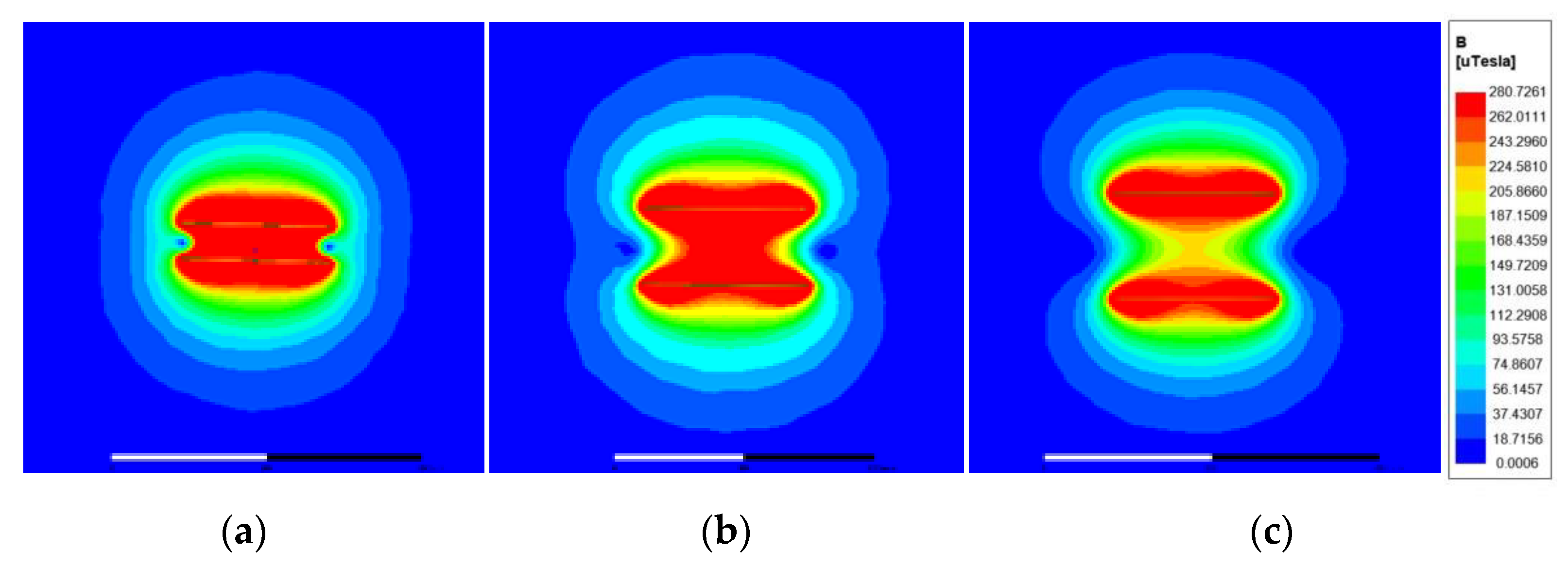
When the operating frequency is fixed at a certain frequency band, a standard value of the referenced magnetic flux density is fixed. However, the transmission distance may not remain the same when charging different EVs. Therefore, the magnetic flux density will increase or decrease accordingly with the distance. As the transmission distance is shortened, the EMF leakage of the WPT system will increase accordingly. To ensure that the EMF leakage is within the safe range of ICNIRP, the adoption of the proposed dynamic shielding scheme can adjust VA accordingly. This causes the adjusted EMF leakage to drop below the reference level of ICNIRP 2010. While the transmission distance increases, the EMF leakage will become lower accordingly. From the perspective of energy saving and cost saving, VA should be reduced accordingly, which can help to ensure that the EMF leakage is within the safety limit of the ICNIRP 2010 standard and prevent excessive waste of resources.
The proposed dynamic shielding scheme is applicable to cases in which the transmission distance changes. It has a certain directive significance for future research on shielding technology for subsequent WPT systems.


