Article

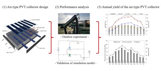
Simulation and Performance Analysis of Air-Type PVT Collector with Interspaced Baffle-PV Cell Design

1
Department of Energy Systems Engineering, Kongju National University, Cheonan 31080, Korea
2
Green Energy Technology Research Center, Kongju National University, Cheonan 31080, Korea
3
Department of Architectural Engineering, Kongju National University, Cheonan 31080, Korea
*
Author to whom correspondence should be addressed.
Energies 2021, 14(17), 5372; https://doi.org/10.3390/en14175372
Submission received: 1 July 2021 / Revised: 18 August 2021 / Accepted: 19 August 2021 / Published: 29 August 2021
(This article belongs to the Special Issue Building Energy and Environment)

Abstract

:
A Photovoltaic Thermal (PVT) collector produces heat and electricity simultaneously. Air-type PVT collector uses air as a transfer medium to take heat from PV back side surface. The performance of the air-type PVT collector is affected by design elements such as PV types, inside structures in heat collecting space (baffle or fins), the shape of the air pathway, etc. In this study, an advanced air-type PVT collector was designed with curved baffles (absorber) to improve thermal performance. Within the air-type PVT collector, PV cells were arranged in an interspaced design, and the curved baffles were located in the collecting space to increase heat efficiently. The absorber received solar radiation directly and was utilized as baffles for improving thermal performance. The air-type PVT collector was fabricated and tested in an outdoor environment considering the climatic conditions of Daejeon, Republic of Korea. In addition, based on experiment parameters and data, the annual thermal and electrical performances of the system were analyzed by simulation modeling using the TRNSYS program. Thermal and electrical efficiencies were 37.1% and 6.4% (according to module area) for outdoor test conditions, respectively. Numerical and experimental results were in good agreement with an error of 4% and 0.24% for thermal and electrical efficiencies, respectively. Annual heat gain was 644 kWh th/year, and generated power was 118 kWh el/year.

Graphical Abstract

1. Introduction

A PVT (Photovoltaic Thermal) collector produces heat and electricity simultaneously. Electricity is generated by the working principle of solar radiation absorbed by PV cells located at the front of the PVT collector. Concurrently, during this operation, heat is produced at the back side of the PV module. The PVT collector harnesses the heat energy for heating indoor building spaces. Consequently, PV electrical efficiency losses due to overheating can be curtailed. PVT collectors can be categorized according to the fluid medium used in air and water types. Air-type PVT collectors are simple to manage compared to water-type, without water leak and condensation problems. Furthermore, a storage or buffer tank is not needed for an air-type PVT. The heated air from the PVT collector can be utilized for various systems such as heat pumps and heat recovery ventilators to improve overall system efficiency. The performance of an air-type PVT collector is affected by the PV module, collector layers and flow path, etc.
Various researchers examined different designs of PVT collectors and related characteristics. For instance, Lammle et al. [1] analyzed PVT collectors with cooling fins and switchable film to prevent overheating. Absorber temperatures of the PVT collectors decreased by 36 °C and 61 °C compared to the standard model. Concerning absorber plates or baffles, Fudholi et al. [2] examined inverted triangle absorbers in a PVT collector. Based on an indoor experiment, exergy efficiency was 12.89%, while numerical analysis yielded an exergy efficiency of 13.36%. Moreover, Srimanickam et al. [3] installed V-shaped baffles in a cooling channel to improve the thermal performance of the PVT collector. The highest outlet temperature of the PVT collector was 53 °C when inlet temperature, ambient temperature, and air flow rate were 38 °C, 42.5 °C, and 64.8 kg/h, respectively. Zhao et al. [4] suggested a hybrid-type baffle with a honeycomb structure for the PVT collector. Experiments were conducted with different PV panel coverage (15–90%) and irradiance levels (200–600 W/m2). The maximum instantaneous thermal efficiency of the PVT collector was when PV panel coverage was 45%. Furthermore, Guruprasd et al. [5] compared PVT collectors with three different air pathways by fins and rectangular baffles in collecting space. Case 3, which had both obstacles (fins and baffles), was shown to have a better thermal performance of 24.8%. Similarly, Kim et al. [6] installed rectangular baffles in a PVT collector connected to Heat Recovery Ventilator (HRV). The thermal and electrical efficiencies of the PVT collector were 23% and 15%, respectively. Moreover, system performance increased by 10% compared to a single HRV. Likewise, Yu et al. [7] improved thermal performance by using triangular baffles. The temperature increased by 4 °C compared to the standard PVT collector. Moreover, thermal efficiency improved by 31%.
The above-mentioned studies were based only on experimental investigations. However, using experimental and Computational Fluid Dynamic (CFD) procedures, Kim et al. [8] analyzed the appropriate size of rectangular baffles for the PVT collector. The integrated CFD and experimental methods resulted in an optimized size of the rectangular baffles under 150 mm and an installation slope of more than 30°. Towards optimizing thermal and electrical efficiencies of PVT, Bambrook et al. [9] conducted outdoor experiments on PVT collectors with different duct sizes, flow rates, and so on. Thermal and electrical efficiencies were 28–55% and 10.6–12.2%, respectively. In terms of energy consumption, optimum flow rates ranged from 0.03 to 0.05 kg/(s × m2). Moreover, Golzari et al. [10] found that the thermal transfer coefficient of a PVT collector with Coro na wind increased by 65%, corresponding with the thermal efficiency of 28.9% for the PVT collector. Other researchers installed porous metal foams between PV and collecting space [11]. It was found that the thickness of the porous metal foam should be under half of the collecting space thickness. Moreover, electrical and thermal efficiencies could be improved by a maximum of 4% and 40%, respectively. Some studies [12,13] used impinging jets to achieve high heat transfer for absorber plates located in the PVT collector.
Related to building integration and annual thermal and electrical yields, Shahsavar et al. [14] analyzed the annual performance of Building integrated PVT (BIPVT) using a modeling and simulation approach. Power generation was highest in July and lowest in December for the Iran (Kermanshah) climate. Annual power generation and heat gain were computed to be 1096.1 kWh el/year and 32,774.2 kWh th/year, respectively. Further studies based on numerical analysis of PVT collectors were conducted and validated with outdoor experiments [15,16,17]. Concerning a typical heat transfer media, some researchers investigated the performance of the PVT collector using nanofluids as a heat transfer medium [18,19]. The studies were based on theoretical values and data from previous research. Moreover, the performance of the semi-transparent PVT collector was analyzed and validated with mathematical modeling and outdoor experiment [20].
Generally, findings in the literature show a range of electrical and thermal efficiencies due to the sensitivity of PVT collectors to local climate, as well as different PVT collector configurations aimed at maximizing specific outputs. For instance, some PVT designs focused on preventing overheating, improving thermal performance, optimizing air flow rate, or insulating and optimizing the collecting space thickness. In addition, analyses are often carried out for certain seasons/periods and not the entire year. Moreover, PVT design concepts investigated in the literature did not account for dynamic solar altitude due to changing seasons. Most studies were based on PVT collectors with generic PV cell modules. These reasons show research gaps and present opportunities for further studies.
The purpose of this study is to analyze the performance of an air-type PVT collector designed with interspaced baffle-PV cell design. The study is based on robust outdoor experiments and simulation methods. For this study, an air-type PVT collector was designed and manufactured with curved baffles to improve thermal performance and to account for changing solar altitude. To maximize the absorption of solar radiation, transparent glass areas were interspaced with PV cells. In addition to outdoor tests, the electrical, thermal performances of the air-type PVT collector were examined with the TRNSYS simulation program (University of Wisconsin, WI, Madison, USA) using experimental data. Based on the validated TRNSYS model, the annual yield of the collector was also evaluated in this study.

2. Methods

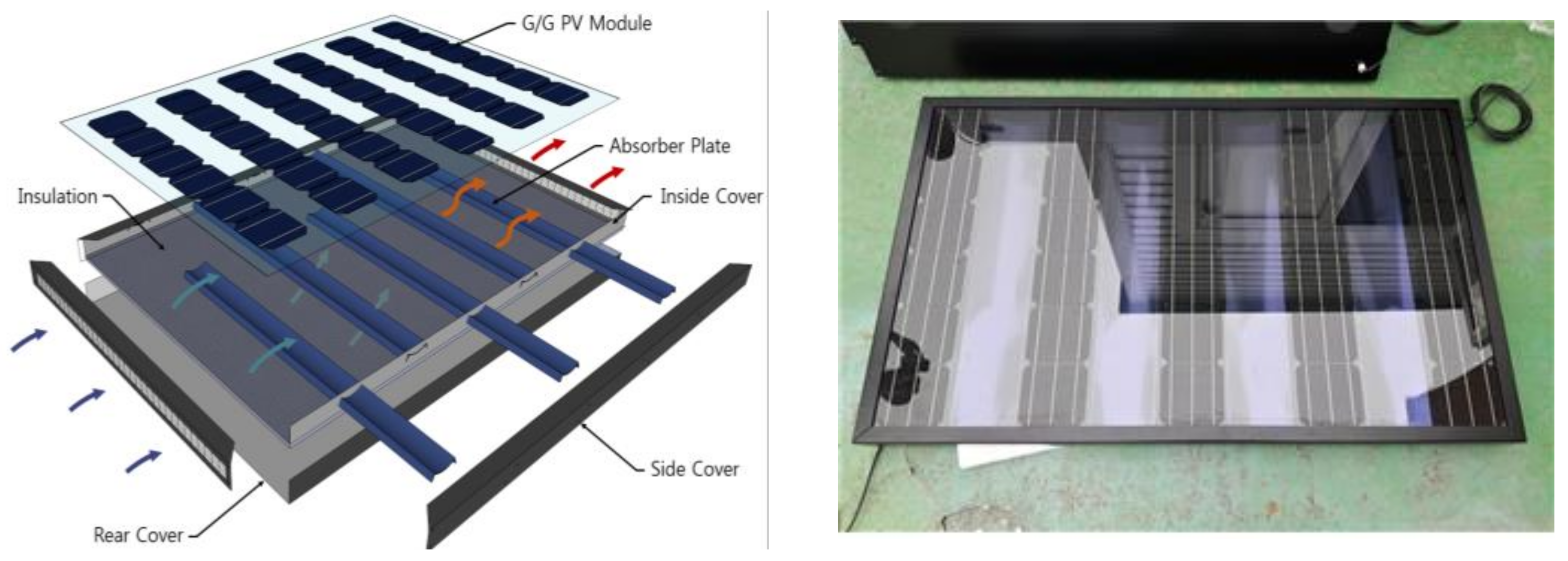
2.1. Design Theory and Fabrication of Air-Type PVT Collector

The PVT design concept was proposed to improve thermal performance considering two main elements. The first was to maximize the absorption of solar radiation. For this purpose, a G/G (Glass to Glass) PV module with different arrangements of the PV cells to improve accumulated heat passing through the transparent space between PV cells was used (Figure 1). The second element was to account for dynamic solar altitude due to different seasons. Therefore, curved baffles made with absorber plates were installed between PV cells in the collector. The shape of baffles was designed to maximize absorbed solar radiation with different incident angles and to collect heat efficiently. The baffles created efficient air movements and absorbed heat as obstacles. As a result, air would swipe the back side of the PV module to effectively cool it down.
The air-type PVT collector was designed to focus on heat collecting. The size of the collector is 1.63 m2, with 0.08 m of height for collecting heat behind PV. The capacity of the PV module is 123.3 W, and electrical efficiency is 17.29% (Table 1).

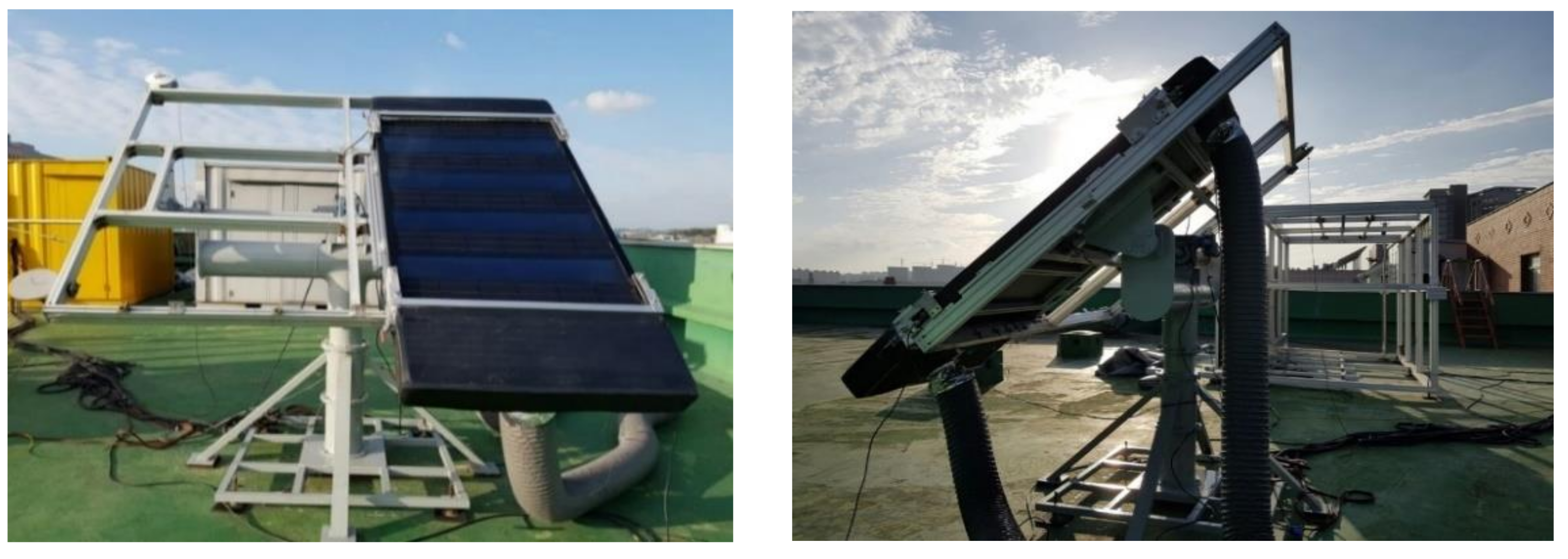
2.2. Outdoor Experimental Setup

An outdoor experiment for the air-type PVT collector was carried out under steady state conditions based on ISO 9806. The experimental setup was installed on the campus of Kongju National University, Cheonan City, South Korea. The collector was mounted on a solar tracker, which can be controlled on the x and y axis. The headers were fixed on the top and bottom of the collector to circulate air fluid. The experiment was an open loop system that uses ambient air for the PVT inlet, and PVT outlet air is exhausted outside. PVT inlet temperature can be set in the chamber. The air was blown into the inlet header of the collector and exited through the outlet header (Figure 2).
Thermocouples, humidity sensors (Th1, Th2), and air flow meters (Fm1, Fm2) were installed to measure temperature, humidity, and air flow data for the experiment. The pyranometer was located 1 m beside the air-type PVT collector at an equivalent degree (Figure 3). Furthermore, 8 point temperature sensors were set at the inlet and outlet ducts of the collector to check the temperature uniformity. The experimental conditions were solar radiation greater than 700 W/m2, a flow rate of 80 kg/h, and fluctuation of the inlet, outlet, and ambient temperature within ±0.5 °C. Electrical performance was analyzed at the same operational conditions. The inlet air temperature was set between 20 and 40 °C.

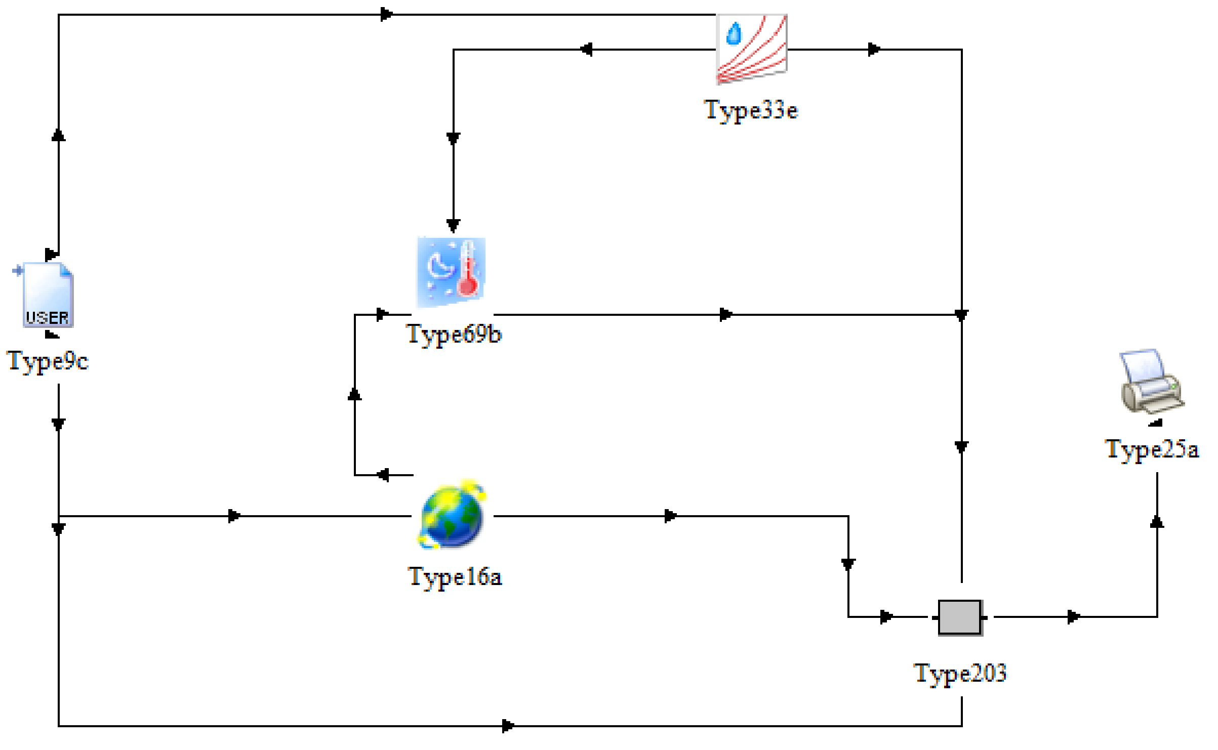
2.3. TRNSYS Model and Simulation

Annual simulations using TRNSYS were conducted to analyze the long-term performance of the collector with type 203 component, which was developed by CanmetENERGY in Natural Resources Canada and Kongju National University, funded by an international cooperative research project. TRNSYS is a simulation program used for modeling buildings and equipment, including alternative energy systems such as solar, photovoltaic, wind, etc. The simulations are constructed by connecting components models to compute performance. A simplified flow diagram and setup of the PVT system in the TRNSYS environment are shown in Figure 4.
The output is conducted with parameters and inputs of the component. The type 203 component reflects design characteristics (PV cells arrangement, curved baffle, and inside structure, etc.) of the air-type PVT collector based on indoor experimental data and numerical analysis.
The parameters and inputs of type 203 for simulation are summarized in Table 2. The values are based on material properties and experimental data. The solar cells area was 0.91 m2, and the absorptance of curved baffles was 0.95. The radiation and ambient temperature inputs were set as 850–1100 W/m2 and 28–30 °C to compare with experimental data. Inlet air temperature and flow rates were 35 °C and 80 kg/h, respectively.

3. Results and Discussion

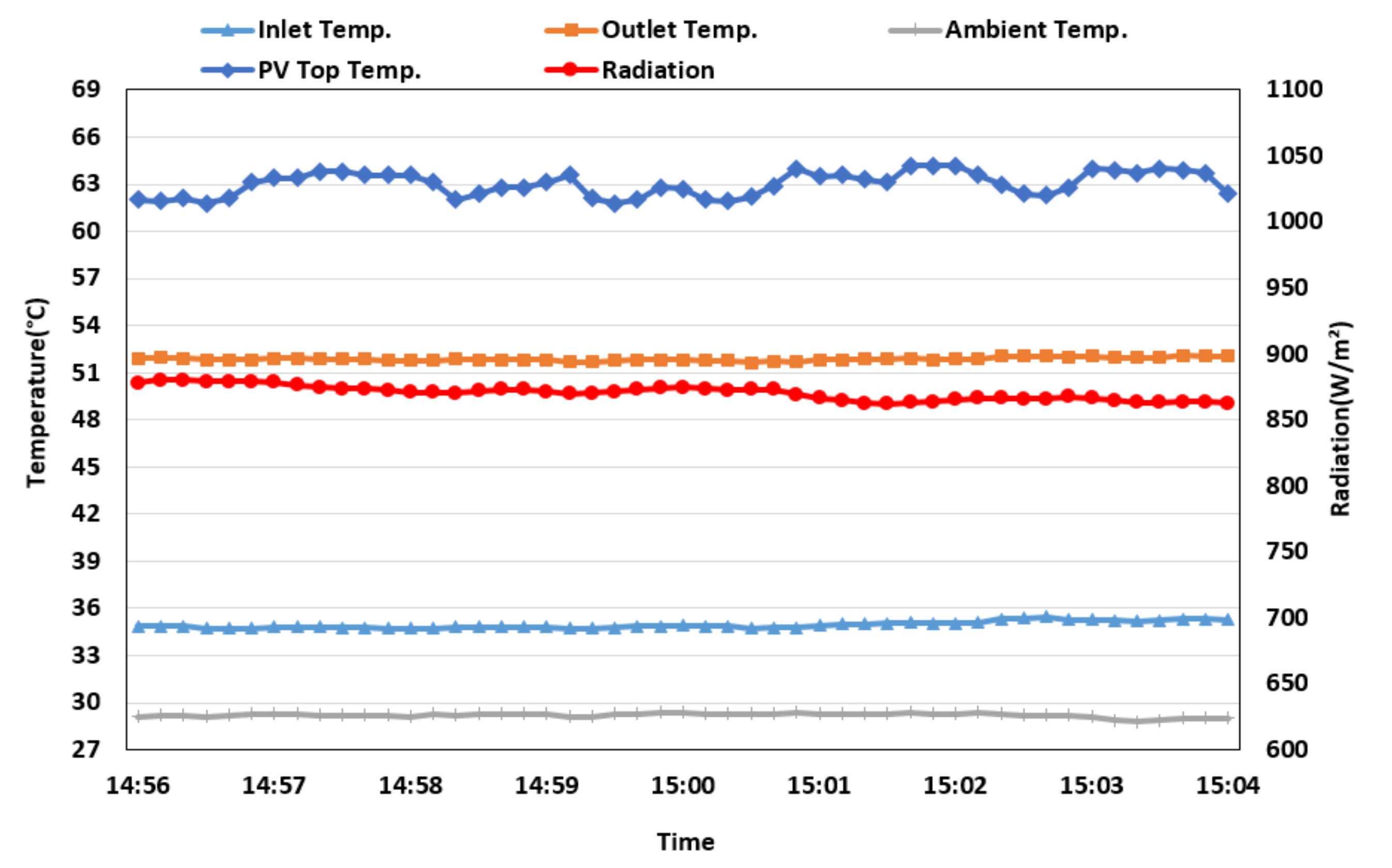
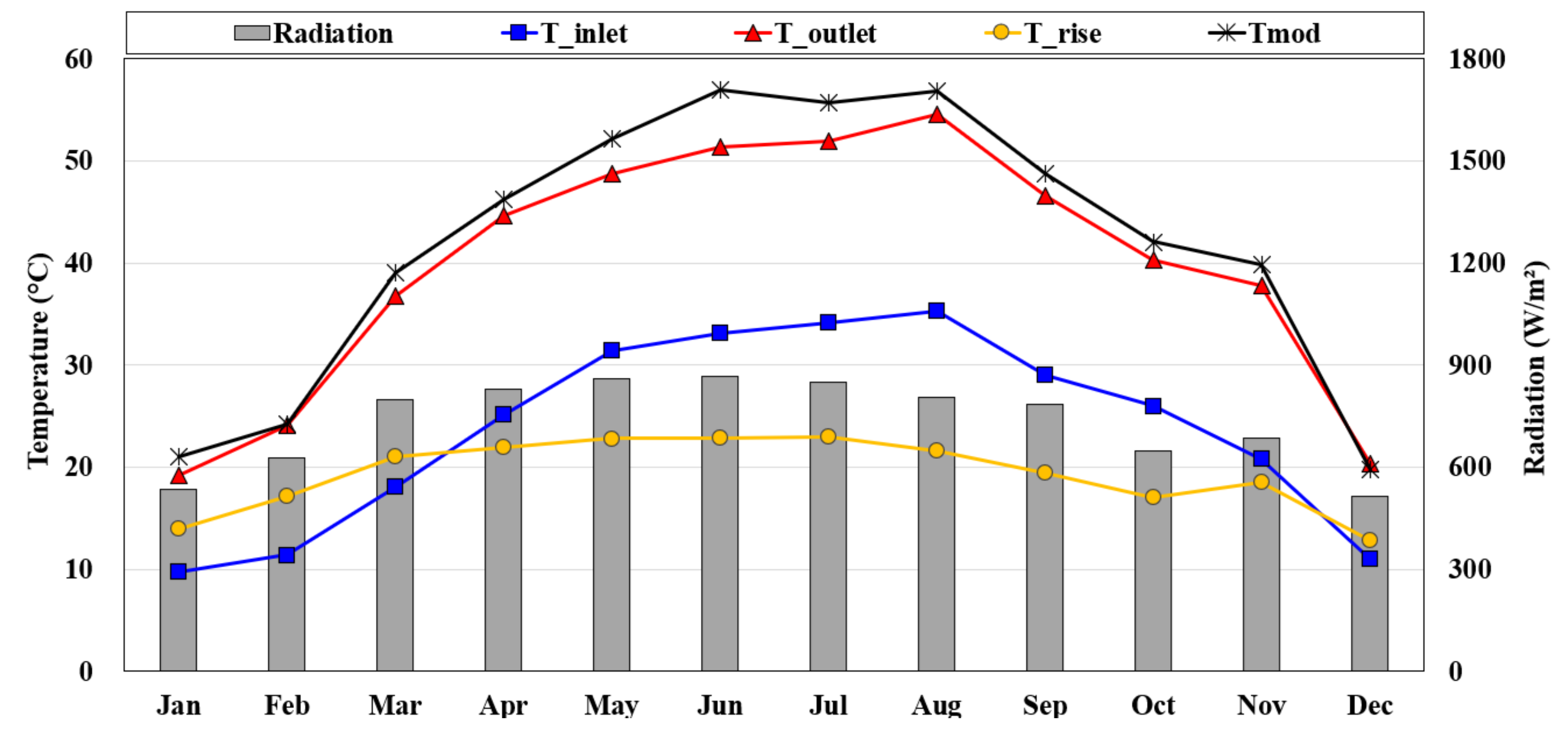
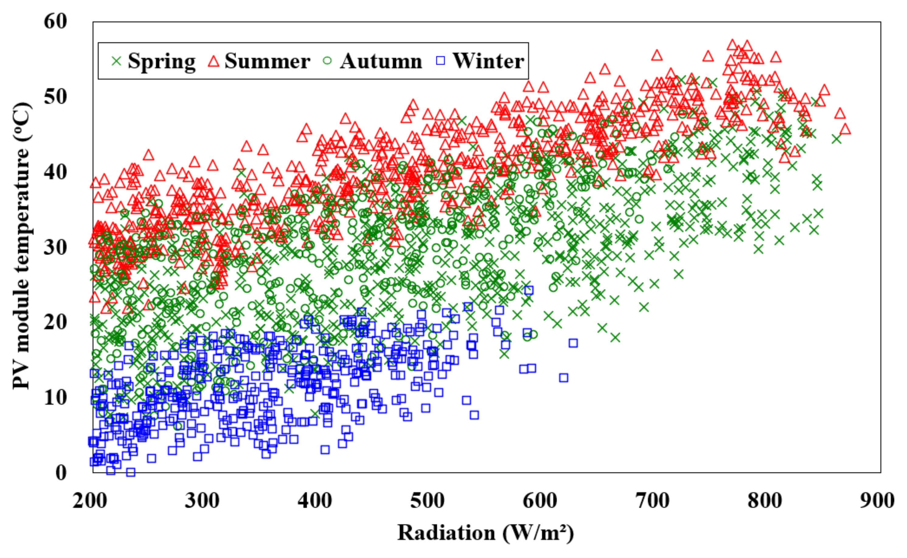
3.1. Outdoor Temperature Characteristics

Figure 5 shows the temperature characteristics of the air-type PVT collector. The outlet air temperature of the collector was 53 (±0.5) °C when the inlet temperature, radiation, and flowrate were 35 (±0.5) °C, 870 (±30) W/m2, and 80 kg/h, respectively. The temperature difference (∆T) between inlet and outlet was 18 (±0.5) °C when the PV top temperature was 63.5 (±1) °C.

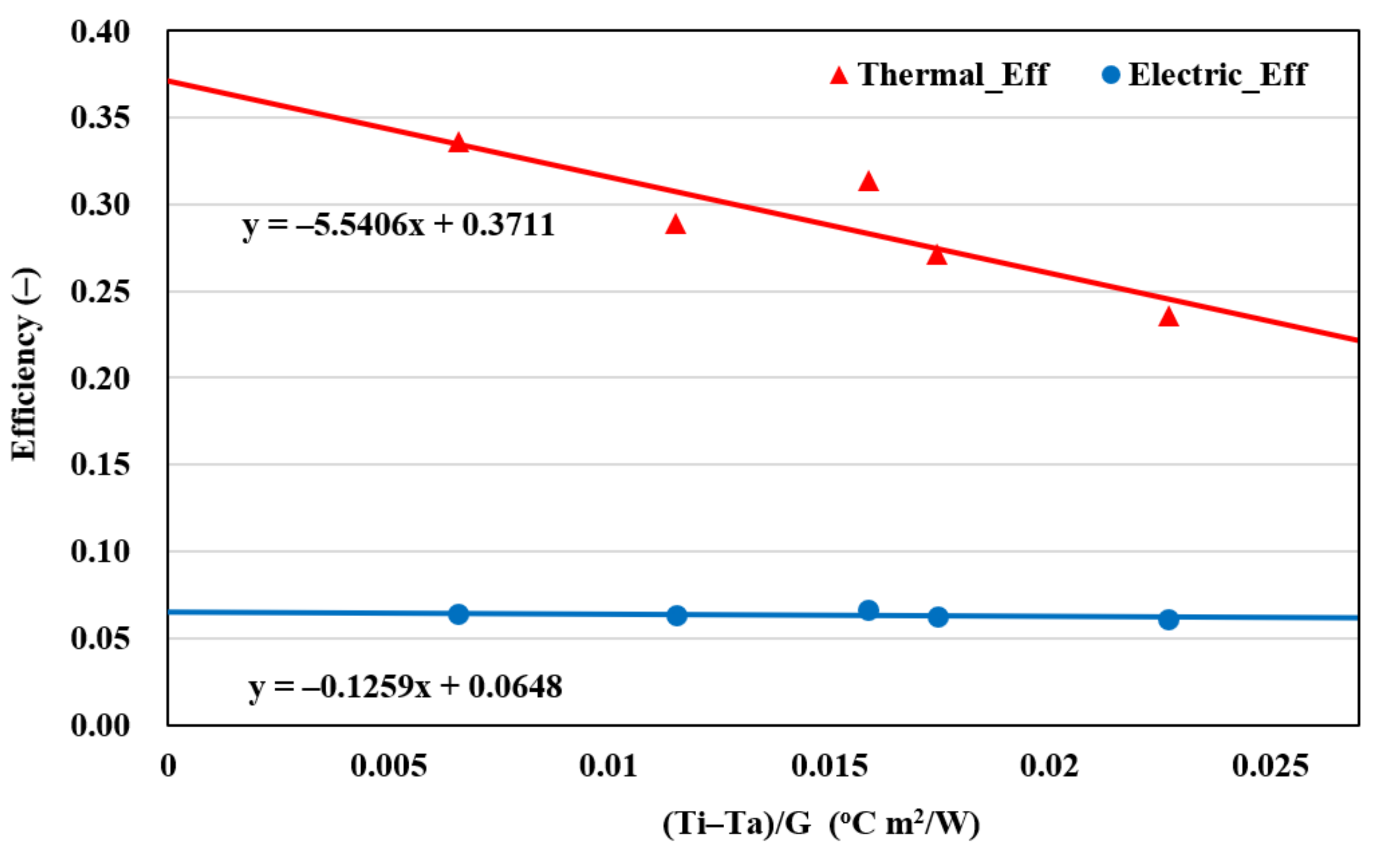
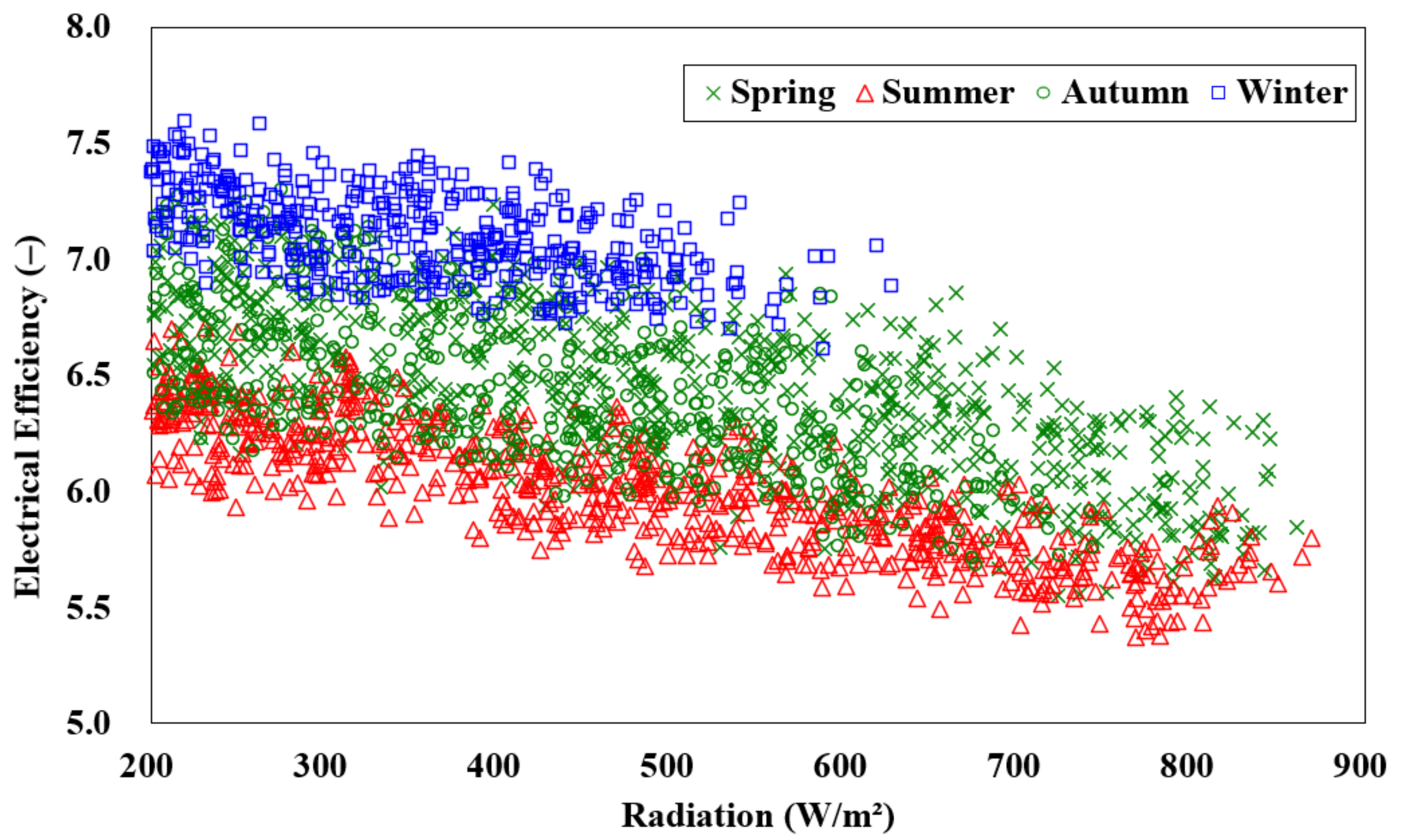
3.2. Thermal and Electrical Performance Based on Experiment

Thermal and electrical efficiencies of the air-type PVT collector are plotted in Figure 6. In Figure 6, the X axis is a coefficient determined in relation to ambient temperature, inlet temperature, and radiation. Similarly, the Y axis is the thermal and electrical efficiencies of the collector. Conventionally, equations of the form y = ax + b are used to characterize the performance coefficient for the PVT collector. The efficiencies were calculated using Equations (1) and (2). Based on collector area and when there were no heat losses (temperatures of inlet and ambient were equal), the thermal and electrical efficiency of the air-type PVT collector were 37.1% and 6.5% (referring to the coefficient of b for thermal efficiency and electrical efficiency equations in Figure 6), respectively. There was no decrease in electrical efficiency as the air carried away heat from the back side of the PV module.
η t h = m ˙ C p T o T i A p v t × G
η e l = I m × V m A p v t × G
η t h  Thermal efficiency (-).
m ˙  Air flow rate (kg/h).
T o  Outlet air temperature (°C).
T i  Inlet air temperature (°C).
G  Solar radiation (W/m2).
C p  Specific heat of air at constant pressure (J/(kg × °C)).
η e l  Electrical efficiency (-).
I m  Maximum current (A).
V m  Maximum voltage (V).
A p v t  Surface area of the collector (m2).

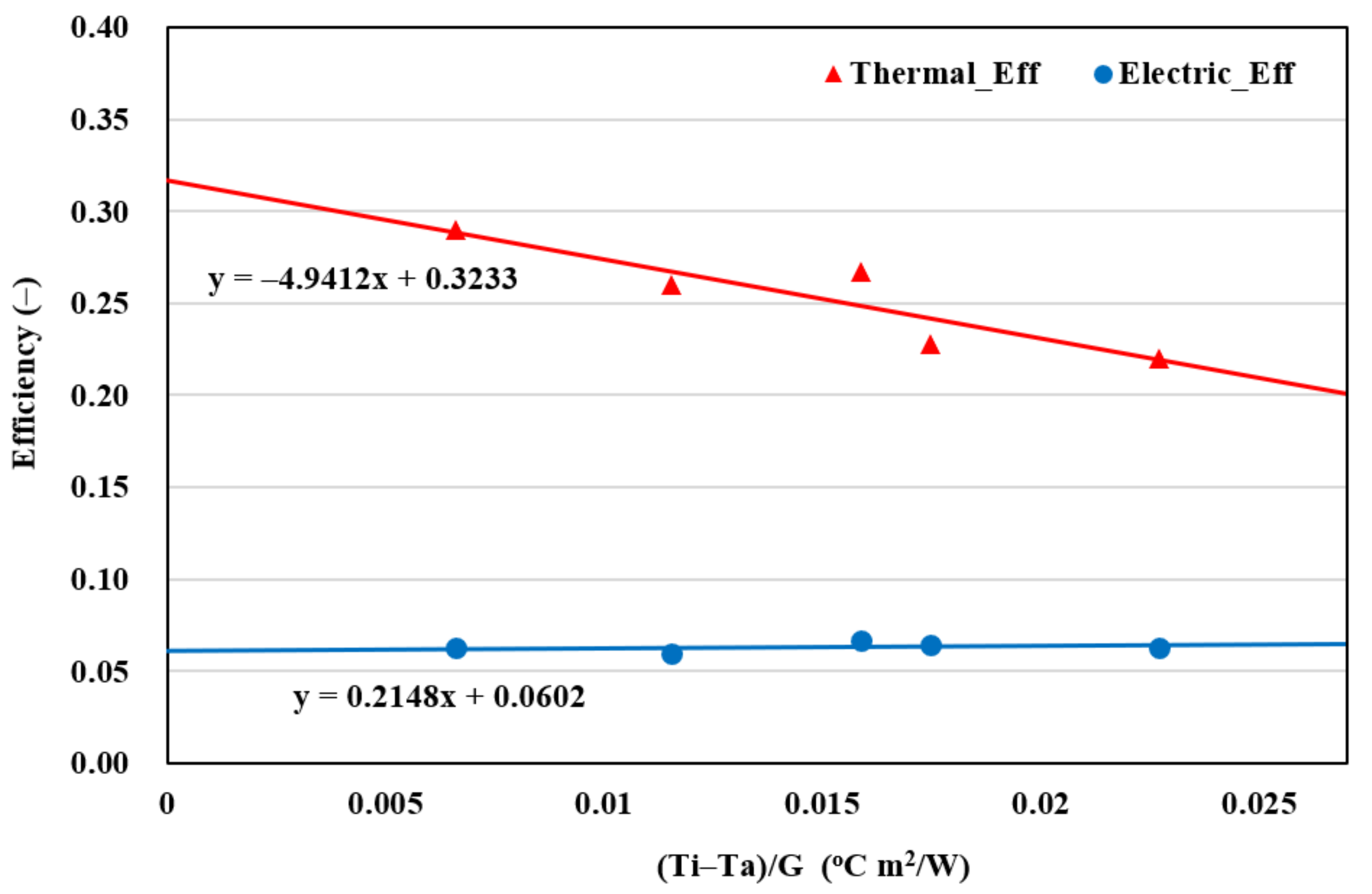
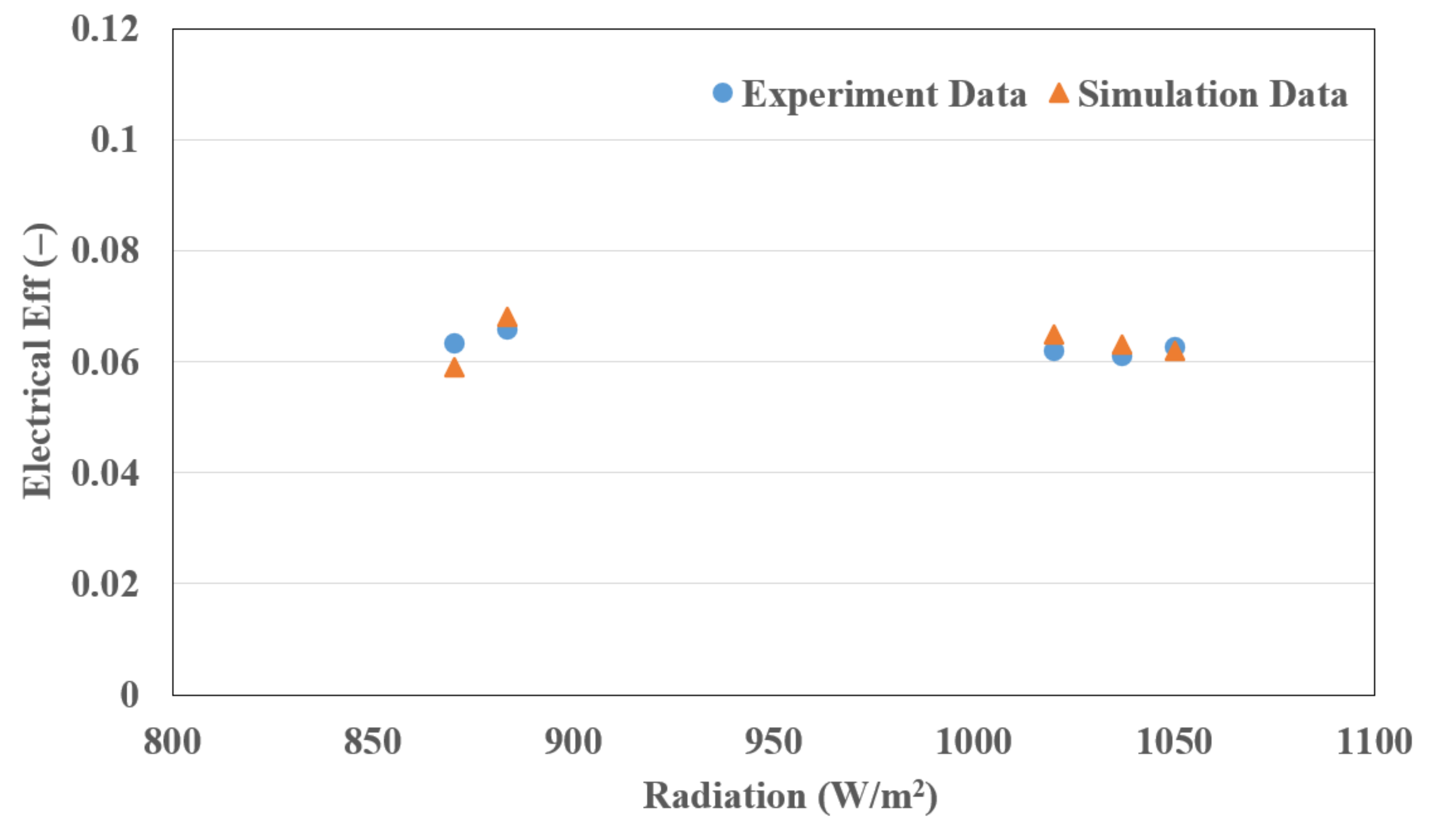
3.3. Comparison of Simulation and Experimental Results

According to the simulation results, thermal and electrical efficiencies of the air-type PVT collector were 32.3% and 6.0% (referring to the coefficient of b for thermal efficiency and electrical efficiency equations in Figure 7), respectively, which were lower than for outdoor experiments (thermal efficiency of 37.1% and electrical efficiency of 6.5%). Although there were no electrical efficiency losses, the heat loss coefficient was 4.94 (from the coefficient of x for the thermal efficiency equation in Figure 7). Figure 8 and Figure 9 presents a comparison of simulation and experiment results. Thermal efficiencies based on simulation evaluations were 24–34%, while that for experiments were 21–29%, according to radiation. Electrical efficiencies were 6.1–6.5% for simulation evaluations and 5.9–6.8% for experimental assessments, at the same conditions. The simulation and experimental results showed similar patterns with changing conditions (radiation, ambient temperature, etc.). The bias error was −4% and −0.24% for thermal and electrical efficiencies, respectively.

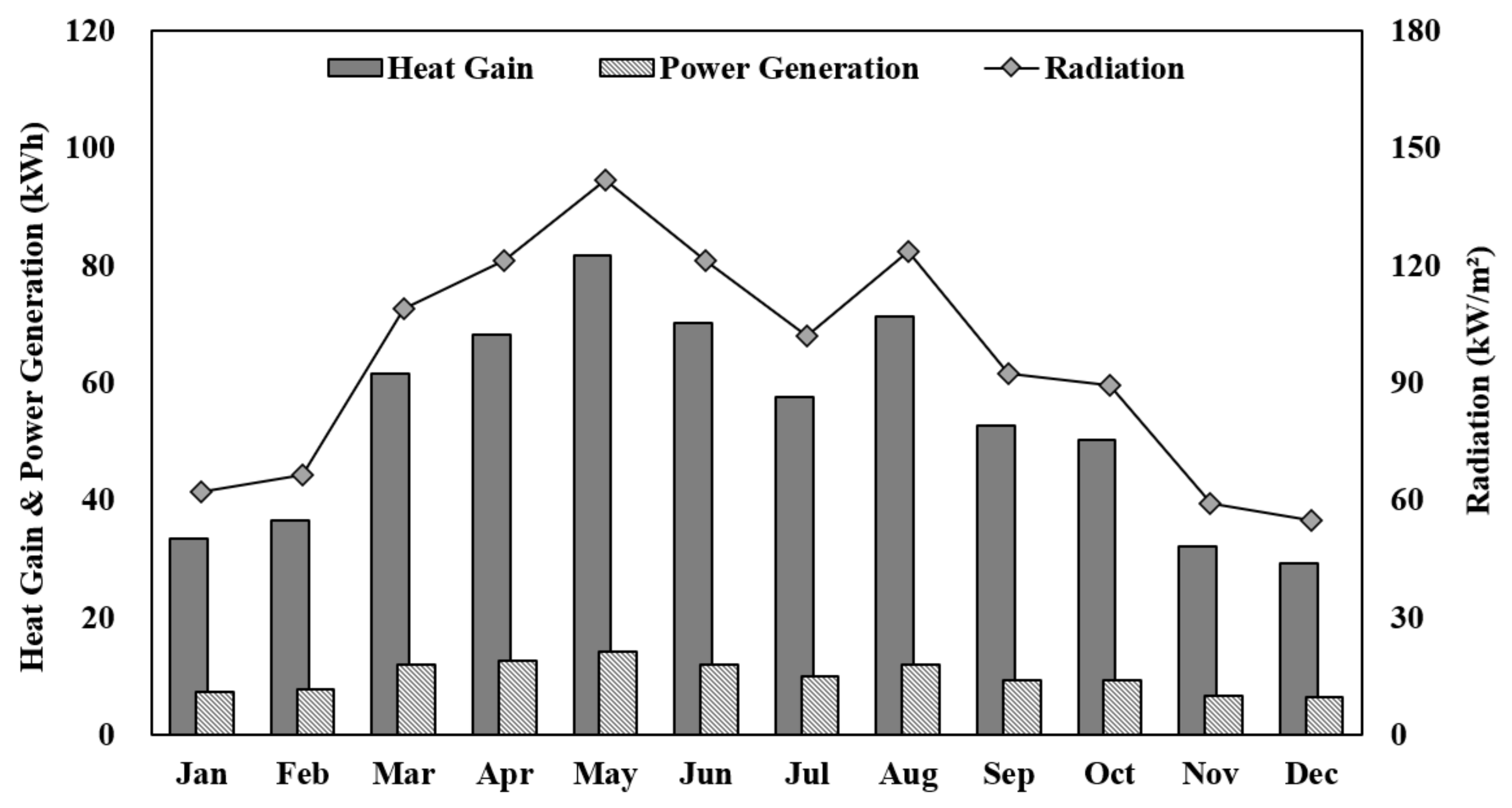
3.4. Annual Performance Analysis of Air-Type PVT Collector

Annual heat gain and power generation of the air-type PVT (1 collector) were evaluated on a simulation basis using type 203 in TRNSYS. The weather data of the Daejeon region (36.35° N, 127.38° E) in TMY2 format was used for the simulation.
Figure 10, Figure 11 and Figure 12 show the annual temperature variations for the PVT collector. The temperature at the back side of PV continuously increased and peaked in June and August at 56 °C. The ambient air was used as an inlet medium to take heat from the PVT collector into the collecting space. The outlet temperature increased to a maximum of 55 °C in August when inlet air temperature, solar radiation, and flow rate were 35 °C, 880 W/m2, and 80 kg/h, respectively. Temperature rise (∆T) was dominant from May to July at 23 °C, and lowest in December at 13 °C.
Heat gain of the PVT collector was 29.24 kWh th minimum in December and 81.67 kWh th maximum in May (where kWh th is annual heat gain and kWh el is annual power generation). The power generation of the PVT collector showed parallel results with heat gain. The minimum power generation of PVT collector was 6.36 kWh el in December and showed a maximum of 11.85 kWh el in May. High collector temperature was expected in May with strong radiation, but the cooling effect was caused by efficient air movement that dissipated heat from the back side of the PV module. Thus, higher thermal and electrical performances ensued compared to other months. Heat gain and power generation in July were lower than in May, June, and August because of the rainy season in South Korea.
Seasonal heat gains and power generation were 198.97 kWh th, 33.63 kWh el (June–August, summer), 99.12 kWh th, 21.27 kWh el (December–February, winter), 211.19 kWh th, 38.54 kWh el (March–May, mid-term 1), and 134.80 kWh th, 25.24 kWh el (September–November, mid-term 2). Heat gain and power generation of mid-term 1 were higher than summer because of the rainy season in July. Annual heat gain and power generations were 644 kWh th/year and 118 kWh el/year, respectively (Figure 13).

4. Conclusions

In this study, an air-type PVT collector with curved baffles was designed, and its thermal and electrical performance were investigated based on an outdoor experiment. Moreover, Annual performance was predicted using the TRNSYS simulation based on the PVT collector’s design characteristics and experimental data.
With the outdoor experiment, the thermal and electrical efficiency of the developed PVT collector were 37.1% and 6.4% (according to module area), respectively. Heat gain was dominant compared to electrical performance according to the design characteristics of the PVT collector.
By comparing experiment and simulation results (based on experiment data), bias error of thermal and electrical efficiencies was −4% and −0.24%, respectively. Moreover, the performance of the PVT collector showed a close pattern with solar radiation.
Heat gain and power generation in the summer season (June, July, and September) were higher than winter season (December, January, and February), 99.85 kWh th/3 months and 12.36 kWh el/3 month, respectively. Although the developed PVT collector was focused on improving thermal performance with a curved baffle and a unique front cells design, there were no electrical efficiency losses due to efficient heat collection.
Annual heat gain was 644 kWh th/year, and generated power was 118 kWh el/year. The developed PVT collector could be preferred in regions where heating demand is dominant. Furthermore, the PVT collector could support the cooling cycle in the air conditioning system in the summer season using dormant heat. This will be investigated in future work.

Author Contributions

Conceptualization, J.-G.A. and J.-H.K.; methodology, J.-G.A.; software, J.-G.A. and J.-S.Y.; validation, J.-G.A.; formal analysis, J.-G.A.; investigation, J.-G.A. and F.E.B.; resources, J.-G.A.; data curation, J.-G.A.; writing—original draft preparation, J.-G.A.; writing—review and editing, J.-G.A. and F.E.B.; visualization, J.-G.A.; supervision, J.-T.K.; project administration, J.-T.K.; funding acquisition, J.-T.K. All authors have read and agreed to the published version of the manuscript.

Funding

This work was supported by the Korea Institute of Energy Technology Evaluation and Planning (KETEP) (No. 20188550000480) and the Korea Energy Agency (No. 20012638), under the Ministry of Trade, Industry and Energy (MOTIE) of the Republic of Korea.

Institutional Review Board Statement

Not applicable.

Informed Consent Statement

Not applicable.

Data Availability Statement

Not applicable.

Conflicts of Interest

The authors declare no conflict of interest.

References

  1. Lämmle, M.; Hermann, M.; Kramer, K.; Panzer, C.; Piekarczyk, A.; Thoma, C.; Fahr, S. Development of highly efficient, glazed PVT collectors with overheating protection to increase reliability and enhance energy yields. Sol. Energy 2018, 176, 87–97. [Google Scholar] [CrossRef]
  2. Fudholi, A.; Zohri, M.; Rukman, N.S.B.; Nazri, N.S.; Mustapha, M.; Yen, C.H.; Mohammad, M.; Sopian, K. Exergy and sustainability index of photovoltaic thermal (PVT) air collector: A theoretical and experimental study. Renew. Sustain. Energy Rev. 2019, 100, 44–51. [Google Scholar] [CrossRef]
  3. Srimanickam, B.; Vijayalakshmi, M.M.; Natarajan, E. Thermal analysis on photovoltaic thermal hybrid system with cooling channel with V-baffles. Indian J. Sci. Technol. 2015, 8, 1–5. [Google Scholar] [CrossRef] [Green Version]
  4. Zhao, Y.; Meng, T.; Jing, C.; Hu, J.; Qian, S. Experimental and Numerical Investigation on Thermal Performance of PV-driven aluminium honeycomb solar air collector. Sol. Energy 2020, 204, 294–306. [Google Scholar] [CrossRef]
  5. Guruprasad, B.; Srimanickam, B.; Natarajan, U.; Malayalamurthi, R.; Elango, A. Performance investigation on various models on solar photovoltaic thermal (PVT) hybrid system. AIP Conf. Proc. 2019, 2161, 020030. [Google Scholar] [CrossRef]
  6. Kim, J.H.; Ahn, J.G.; Kim, J.T. Demonstration of the performance of an air-type Photovoltaic Thermal (PVT) system coupled with a heat-recovery ventilator. Energies 2016, 9, 728. [Google Scholar] [CrossRef] [Green Version]
  7. Yu, J.S.; Kim, J.H.; Kim, J.T. Effect of triangular baffle arrangement on heat transfer enhancement of air-type PVT collector. Sustainability 2020, 12, 7469. [Google Scholar] [CrossRef]
  8. Kim, Y.; Lee, K.; Yang, L.; Entchev, E.; Kang, E.; Lee, E. Validation and numerical sensitivity study of air baffle photovoltaic-thermal module. Energies 2020, 13, 1990. [Google Scholar] [CrossRef] [Green Version]
  9. Bambrook, S.M.; Sproul, A.B. Maximising the energy output of a PVT air system. Sol. Energy 2012, 86, 1857–1871. [Google Scholar] [CrossRef]
  10. Golzari, S.; Kasaeian, A.; Amidpour, M.; Nasirivatan, S.; Mousavi, S. Experimental investigation of the effects of Corona wind on the performance of an air-cooled PV/T. Renew. Energy 2018, 127, 284–297. [Google Scholar] [CrossRef]
  11. Tahmasbi, M.; Siavashi, M.; Norouzi, A.M.; Doranehgard, M.H. Thermal and electrical efficiencies enhancement of a solar photovoltaic-thermal/air system (PVT/Air) using metal foams. J. Taiwan Inst. Chem. Eng. 2021, 124, 276–289. [Google Scholar] [CrossRef]
  12. Barrau, J.; Rosell, J.; Chemisana, D.; Tadrist, L.; Ibañez, M. Effect of a hybrid jet impingement/micro-channel cooling device on the performance of densely packed PV cells under high concentration. Sol. Energy 2011, 85, 2655–2665. [Google Scholar] [CrossRef]
  13. Brideau, S.A.; Collins, M.R. Experimental model validation of a hybrid PV/thermal air based collector with impinging jets. Energy Procedia 2012, 30, 44–54. [Google Scholar] [CrossRef] [Green Version]
  14. Shahsavar, A.; Khanmohammadi, S.; Khaki, M.; Salmanzadeh, M. Performance assessment of an innovative exhaust air energy recovery system based on the PV/T-assisted thermal wheel. Energy 2018, 162, 682–696. [Google Scholar] [CrossRef]
  15. Zhou, C.; Liang, R.; Zhang, J. Optimization design method and experimental validation of a solar Pvt cogeneration system based on building energy demand. Energies 2017, 10, 1281. [Google Scholar] [CrossRef] [Green Version]
  16. Aste, N.; Chiesa, G.; Verri, F. Design, Development and performance monitoring of a photovoltaic-thermal (PVT) air collector. Renew. Energy 2008, 33, 914–927. [Google Scholar] [CrossRef]
  17. Yandri, E. The effect of joule heating to thermal performance of hybrid PVT collector during electricity generation. Renew. Energy 2017, 111, 344–352. [Google Scholar] [CrossRef]
  18. Al-Waeli, A.H.A.; Chaichan, M.T.; Sopian, K.; Kazem, H.A.; Mahood, H.B.; Khadom, A.A. Modeling and experimental validation of a PVT system using nanofluid coolant and nano-PCM. Sol. Energy 2019, 177, 178–191. [Google Scholar] [CrossRef]
  19. Bellos, E.; Tzivanidis, C. Yearly performance of a hybrid PV operating with nanofluid. Renew. Energy 2017, 113, 867–884. [Google Scholar] [CrossRef]
  20. Tripathi, R.; Tiwari, G.N. Annual performance evaluation (energy and exergy) of fully covered concentrated photovoltaic thermal (PVT) water collector: An experimental validation. Sol. Energy 2017, 146, 180–190. [Google Scholar] [CrossRef]
  21. Kim, J.H.; Kim, S.M.; Kim, J.T. Experimental performance of an advanced air-type photovoltaic/thermal (PVT) collector with direct expansion air handling unit (AHU). Sustainability 2021, 13, 888. [Google Scholar] [CrossRef]
  22. Kim, S.M.; Kim, J.H.; Kim, J.T. Experimental study on the thermal and electrical characteristics of an air-based photovoltaic thermal collector. Energies 2019, 12, 2661. [Google Scholar] [CrossRef] [Green Version]
Figure 1. New design of air-type PVT collector for efficient thermal performance. From [21].
Energies 14 05372 g001
Figure 2. Outdoor experimental setup of Air-type PVT collector. From [22].
Energies 14 05372 g002
Figure 3. Location of measurement sensors for the experiment.
Energies 14 05372 g003
Figure 4. TRNSYS flow diagram for the PVT system with type 203 component.
Energies 14 05372 g004
Figure 5. Temperature characteristics of air-type PVT collector.
Energies 14 05372 g005
Figure 6. Thermal and electrical efficiencies of air-type PVT collector based on experiment results.
Energies 14 05372 g006
Figure 7. Thermal and electrical efficiencies of air-type PVT collector based on simulation results.
Energies 14 05372 g007
Figure 8. Comparison of thermal efficiencies for experimental and simulation assessments.
Energies 14 05372 g008
Figure 9. Comparison of electrical efficiencies for experimental and simulation assessments.
Energies 14 05372 g009
Figure 10. Monthly temperature fluctuations for PVT collector.
Energies 14 05372 g010
Figure 11. Annual electrical efficiency variation with solar radiation.
Energies 14 05372 g011
Figure 12. Annual PV module temperature with solar radiation.
Energies 14 05372 g012
Figure 13. Monthly heat gain and power generation of the PVT collector.
Energies 14 05372 g013
Table 1. Specifications of PV used for air-type PVT collector. From [22].
Cell TypeMono-Crystalline Silicon
Module (Cell) efficiency7.33 (17.29)%
Maximum power123.3 W
Maximum voltage15.08 V
Maximum current8.18 A
Open voltage19.05 V
Short current8.61 A
Size (PVT collector)1584 mm × 1031 mm × 84.5 mm
Table 2. Parameters of Type 203 component for TRNSYS simulation.
VariableParameters and Inputs DescriptionValuesUnits
ApvtAir-type PVT collector area1.63m2
AcellSolar Cell area0.91m2
EpvPV glazing emissivity0.90-
AbabAbsorber absorptance0.95-
AbpvPV cells absorptance0.36-
CpvModule temperature coefficient for efficiency(%/°C)−0.50-
EffpvModule electrical efficiency at reference conditions7.33%
TiFluid inlet temperature35°C
FpvtFluid flow rate80kg/h
Publisher’s Note: MDPI stays neutral with regard to jurisdictional claims in published maps and institutional affiliations.

