Article

Improved Microbial Fuel Cell Performance by Engineering E. coli for Enhanced Affinity to Gold

by
Justin P. Jahnke
*,
Deborah A. Sarkes
,
Jessica L. Liba
,
James J. Sumner
and
Dimitra N. Stratis-Cullum
DEVCOM Army Research Laboratory, Adelphi, MD 20783, USA
*
Author to whom correspondence should be addressed.
Energies 2021, 14(17), 5389; https://doi.org/10.3390/en14175389
Submission received: 21 June 2021 / Revised: 4 August 2021 / Accepted: 23 August 2021 / Published: 30 August 2021

Abstract

:
Microorganism affinity for surfaces can be controlled by introducing material binding motifs into proteins such as fimbrial tip and outer membrane proteins. Here, controlled surface affinity is used to manipulate and enhance electrical power production in a typical bioelectrochemical system, a microbial fuel cell (MFC). Specifically, gold-binding motifs of various affinity were introduced into two scaffolds in Escherichia coli: eCPX, a modified version of outer membrane protein X (OmpX), and FimH, the tip protein of the fimbriae. The behavior of these strains on gold electrodes was examined in small-scale (240 µL) MFCs and 40 mL U-tube MFCs. A clear correlation between the affinity of a strain for a gold surface and the peak voltage produced during MFC operation is shown in the small-scale MFCs; strains displaying peptides with high affinity for gold generate potentials greater than 80 mV while strains displaying peptides with minimal affinity to gold produce potentials around 30 mV. In the larger MFCs, E. coli strains with high affinity to gold exhibit power densities up to 0.27 mW/m2, approximately a 10-fold increase over unengineered strains lacking displayed peptides. Moreover, in the case of the modified FimH strains, this increased power production is sustained for five days.

Graphical Abstract

1. Introduction

Biology has many unique characteristics leading to applications in sensing [1], actuation [2,3], energy conversion [4], waste breakdown [5] and material generation. The control of bacteria–surface interactions is often critical to interacting biology with artificial devices to create biohybrid systems. Microorganisms grow and behave differently on surfaces versus in suspension and have a number of natural mechanisms to control adhesion, including cell membrane-embedded proteins, protein-assembled appendages (e.g., fimbriae and flagella) and extracellular polysaccharide scaffolds [6].
There is also extensive literature on developing short amino acid sequences (peptides) with affinity for a wide range of material sets [7,8]. These peptides can be developed from screening peptide libraries, rational design and isolation from organisms with natural affinities. Peptides have been isolated to employ their interactions with a wide array of materials ranging from soft [9] to hard materials [10,11] and also for nanoscale materials such as carbon nanotubes [12] and a range of nanoparticles [13]. Peptides can bring dissimilar materials together in novel configurations [14] and template materials for energy conversion and other applications [15,16]. They can also be engineered into microorganisms, including outer membrane proteins, fimbriae and other structures to change the adhesion behavior of microorganisms. By incorporating material binding peptides, it has been possible to use living cells to template them on surfaces [11], to bind nanoparticles [17] and to create biohybrid devices [1].
Microorganism–surface interactions play an important role in many bioelectrochemical systems where electrons are transported between an electrode surface and a microorganism either directly or through a variety of redox mediators [18,19]. Microbial fuel cells, where organic matter is broken down to produce electrical power, is a prominent example of a bioelectrochemical system [20,21]. It has been of interest for applications such as waste water treatment and remote power generation, but its adoption has been hindered by issues such as biofouling limiting its long-term operation [22]. Alternatively, in bioelectrochemical synthesis, electrical energy can be used to enable microorganisms to reduce substrates, in some cases allowing the reduction of inorganic carbon into biomass [23]. It is also possible to use electronic signals to transmit information to and from microorganisms, either to use microorganisms as sensors or to trigger gene expression [24,25]. These bioelectrochemical systems can also be readily miniaturized with potential applications moving towards self-powered sensors [26]. In each of these applications, electron transport between microorganisms and electrode surfaces is critical for their efficient operation and, therefore, this should be a promising area for engineering improved affinity between microorganisms and surfaces.
A variety of approaches have been used to improve charge transport. Usually electrode–microorganism charge transfer is improved by the addition of soluble redox mediators [27]. It is also possible to increase charge transfer via membrane stains [28] or by immobilizing nanoparticles on the membrane [29]. Various methods to control interactions at the surface have also been used. For example, redox mediators have been tethered to the electrode surfaces to improve charge collection [30,31]. These tethered mediators are not designed to increase microorganism–surface affinity but simply to concentrate redox mediators where they are most useful, near the electrode surface. Alternatively, surface functionalities have been introduced to affect the electrode–cell interactions; in some cases this has involved the introduction of charge or other non-specific interactions [32,33], but more specific and intimate connections can also be introduced through the use of recombinant membrane-bound proteins [34,35]. Alternatively, in principle, the microorganism can be engineered to have an improved affinity towards the substrate, although this imposes a metabolic cost on the microorganisms and did not result in enhanced power generation when attempted with Shewanella oneidensis on gold electrodes [36].
Here, we show that E. coli can be engineered to have increased affinity for gold and that this can lead to enhanced microbial fuel cell (MFC) performance as measured by power output. Gold was chosen because of its widespread use in sensing and micropatterned devices. It is a common target for peptide discovery, with many papers having developed and validated peptides with high affinity for it [10,13,37,38,39,40]. To investigate the generality of this effect, we use two different scaffolds and show that this effect can be observed in both. The first scaffold, eCPX, is a modified version of the coat protein OmpX [41,42], while the other scaffold relies on the overexpression and alteration of the fimbriae, which are extracellular protein stalks that are implicated in bacterial adhesion [43]. The extensive literature available for gold-binding peptides allowed for the introduction of a series of scaffold changes to control the strength of affinity for gold. These strains were tested in the microliter (µL) MFCs, where a clear trend of increasing MFC voltage with increased binding to gold was observed. The best strains from the µL-MFCs were tested in larger U-tube MFCs, with both scaffolds showing an initial increase in power over unengineered cells. The increase in power generation of for the MFCs with bacteria displaying the fimbriae scaffold was sustained over the length of the experiment, ultimately resulting in 10 times more power produced than the control MFCs after five days.

2. Materials and Methods

2.1. Scaffolds and Cell Culturing

For inducible bacterial peptide display by eCPX, MC1061 E. coli containing pDSJR plasmid (CmR) with P2X removed [17] (referred to as “no cys no P2X”) or pB33-nl3 (CmR) with or without P2X [11,44] (referred to as “cys P2X” and “cys no P2X”, respectively) were used. Both are pBad33-eCPX variants, with the pB33-nl3 having CTSGQ leading peptide at the N-terminal while pDSJR instead has GTSGQ; all peptides were inserted just after the N terminal of the pB33-nl3 with P2X (“cys P2X”) and are therefore preceded by CTSGQ. With the constitutive FimH scaffold, MG1655 Δfim, ΔrecA E. coli [45] was transformed with pPKL114 (containing fimA-G; AmpR) with or without co-transformation of pGB (containing fimH; CmR) [46]. These materials for display on FimH were generously provided by E. V. Sokurenko. Samples without pGB plasmid were labeled ΔFimH due to the absence of the FimH protein, while J96 refers to an unmodified mannose-binding FimH [47] and p8#9 refers to the FimH protein where the p8#9 peptide was inserted with a 6xHis tag at residue Ile 52 of the mature protein [43]. All strains were grown overnight at 37 °C, 225 RPM in 5 mL Luria Broth-Miller (LB, Thermo Fisher) supplemented with appropriate antibiotics (25 µg/mL chloramphenicol, LB Cm25, for all pB33-nl3 and pDSJR constructs; LB supplemented with 100 µg/mL ampicillin (Amp100) with or without addition of 34 µg/mL chloramphenicol (Cm34) for display of FimA-G with or without FimH). Overnight cultures were diluted 1:50 in 3 mL fresh LB containing the same concentration of appropriate antibiotics and grown for about 1 h 45 min (or 1.75 h) at 37 °C, shaking at 225 RPM until the optical density at 600 nm (OD600) of the cultures for display on eCPX (MC1061 cells with pDSJR or pB33-nl3) approximately equaled 0.5 (OD600 range of all cultures, including those for display on FimH, was 0.47–0.56). At this OD600, the cultures for inducible display of eCPX were induced for 1 h with 0.04% w/v L-arabinose at 37 °C, shaking at 225 RPM, while the cultures for display on FimH continued to incubate for another hour without induction. The final OD600 was approximately 1.0 for inducible eCPX display and 1.2 for constitutive FimH display. Samples were placed on ice.

2.2. Gold-Binding Spot Assay

For each sample prepared above, 2 µL of culture in LB medium was spotted onto three separate gold-coated silicon wafers and incubated at room temperature (approximately 22 °C) for 20 min in a covered petri dish. Wafers were then quickly rinsed with PBS 1% Tween-20 (PBS-T) by pouring buffer into the dish while avoiding direct contact with the gold, and then rotating the plate by hand in a figure eight motion several times. The wafers were then washed vigorously by transferring to 50 mL conical tubes containing 20 mL PBS 1% Tween and incubating at room temperature, 150 RPM for 30 min on a rotating shaker with each conical tube laying sideways and the gold-coated/cell exposed side of the wafers facing up. The wafers were then rinsed several times with ddH2O, shaking by hand in the 50 mL conical tubes, to remove detergent and salt in preparation for SEM imaging. Gold-coated wafers were dried with coated side up in a petri dish at 37 °C for about 10 min before photographing the wafers (Figure S1) and SEM imaging of the center of each spot (Figure S2). All SEM imaging was performed under high vacuum using an FEI Quanta 200F environmental SEM with a 5 kV accelerating voltage.

2.3. Microbial Fuel Cells (MFCs)

Two types of MFCs were used in these experiments. The µL-MFCs were constructed according to literature designs with some modifications [48]. Gold-coated glass slides were used for both the anode and cathode (active areas of 0.4 cm2) with a Nafion 117 separator, and butyl rubber (0.3 cm thick) was used to create anode and cathode compartments with volumes of 120 µL; the Nafion separator keeps bacteria out of the cathode compartment while allowing redox mediators to move across the barrier. In the anode compartment, cultures with an OD600 of 0.9–1.2 were added, while in the cathode compartment, 100 mM potassium ferricyanide (Sigma-Aldrich) was used as the electron acceptor. U-tube MFCs were also constructed based upon previously reported protocols [28,49]. Twenty mL of LB was used in each of the anode and cathode chambers. Again a Nafion 117 separator was used. At the cathode, a carbon felt electrode was placed partially submerged in the cathode chamber; this allows liquid to wick up the felt. In the wicking region, liquid air and electrode are all in close proximity, allowing oxygen to be used as the electron acceptor [49]. The chambers were autoclaved with the carbon felt cathodes, Nafion separators, LB media and gold anodes in place. Cultures were diluted into the anode compartment to achieve an initial OD600 of 0.005.
For both MFC setups used here, abiotic controls were run using heat-killed cells that were treated at 70 °C for 10 min. Propidium iodide staining (Thermo Fisher #L7007) was used to confirm the effectiveness of the method. This condition was chosen to be as minimally disruptive to the medium and organisms as possible and thereby provide the most relevant abiotic control. It achieved near complete killing while minimally disrupting the cell envelope and retaining any changes in the medium induced by the bacteria. A VMP3 potentiostat from Biologic (Claix, France) was used for all MFC measurements. The MFCs were held at a constant load of 1 MΩ for 5 h before a variable resistance sweep was conducted from 30 to 0.3 MΩ with a logarithmic spacing and a 10 min dwell at each resistance to allow the system to equilibrate. On the eCPX scaffold, peptide expression level inside and outside of the MFCs was determined for those cells expressing P2X at the C-terminus by monitoring median fluorescence intensity and percent binding to a fluorescent tag with affinity for P2X, YPet-Mona (YPet), using fluorescence activated cell sorting (FACS) as previously described in detail [50].

3. Results and Discussion

To examine the relationship between bacterial gold affinity and performance in gold electrode MFCs, a number of strains in two scaffolds were examined in high throughput µL-MFCs. The most promising strains in both scaffolds were then selected for further examination in larger U-tube MFCs. While displaying the scaffolds imposes metabolic costs that reduce MFC performance, increased gold affinity enhances performance and high levels of gold affinity can lead to performance significantly improved over unengineered strains.
Figure 1 illustrates the two scaffolds used and the various alterations used here. Based on known literature trends for gold-binding peptides, a number of modifications were systematically introduced into both scaffolds to create a series of strains with variable affinity towards gold. These modifications include increasing affinity by inserting known gold-binding residues (histidine, cysteine) and/or known gold-binding peptides. They also include removing motifs (fimbrial tip, P2X YPet binding peptide) that have residual affinity towards gold to drive affinity as low as possible. Figure 1A shows a schematic of the fimbriae protruding from a bacterium, with the detailed structure of the tip protein, FimH, shown on the left in green. Three engineered strains were used in this study. All three strains overexpress the fimbriae proteins; in the strain labeled J96, FimH is unaltered. In contrast, in ΔFimH the tip protein is not expressed at all. Finally, as shown in the schematic, a histidine tag along with a gold-binding peptide were inserted at residue 52 of the mature protein, shown with the red ball and arrow, to include a motif for enhanced gold binding. Figure 1B shows the membrane-embedded eCPX scaffold, which does not protrude from the cell as the fimbriae do, but which is expressed in higher copy number. As shown in the right of Figure 1B, two peptides extend from the outer membrane protein and are targets of modification. A base strain (no cys, no P2X) expressed the eCPX scaffold but received no additional engineering to promote affinity towards gold. We had previously created a strain in which the N-terminal end residue was modified to cysteine [44], which is useful here as SH moieties are frequently used for surface attachment in gold-based electrochemical systems [51,52]. Gold-binding peptides were inserted at both termini. On the N terminal side, a variety of gold-binding peptides known from the literature [38,39,40] and listed in Figure 1C were incorporated after a CTSGQ linker, while on the C terminal side, the P2X peptide, a YPet-Mona binding motif with some affinity to gold, was used [17]. Variants of the eCPX scaffold are, therefore, available with and without each of N-terminal cysteine, additional N-terminal gold-binding sequences and C-terminal P2X. The variety of modifications available with the eCPX scaffold allow the relationship between gold-binding strength and microbial fuel cell performance to be probed in detail.
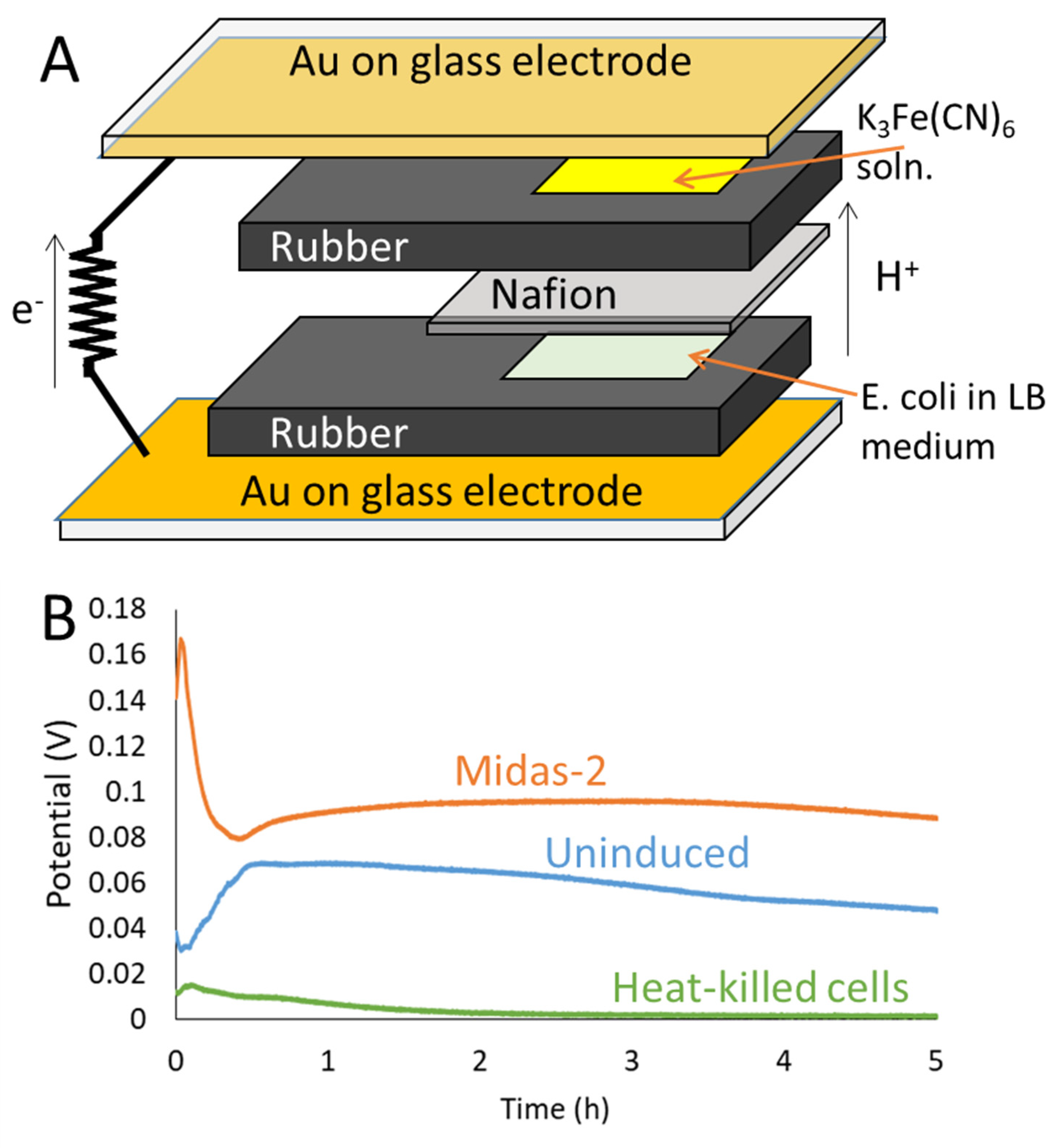
The relationship between binding affinity for gold and the performance of a µL-MFC was investigated by varying the scaffolds and by incorporating a variety of known gold-binding peptides from the literature. A schematic of the µL-MFC is shown in Figure 2A. The setup is analogous to others used in the literature [48,53], using potassium ferricyanide as the terminal electron acceptor and Nafion as the separator membrane. The cells were inoculated at a high OD in the other chamber to enable the fuel cells to rapidly start producing appreciable power and to limit effects from organism growth. Figure 2B shows representative traces over the first five hours for µL-MFCs run under identical conditions but with different strains. The µL-MFCs were held at fixed resistance and the voltage was plotted. Under fixed resistance conditions the current is directly proportional to the voltage and the power is proportional to voltage squared. Within the first 10 min, there can be large changes in voltages due to transient, abiological effects from the initial electrode state and discharge of redox mediators in the media. As expected, heat-killed cells produce almost no voltage after this initial discharge. E. coli strains displaying the scaffold but no gold-binding residues (eCPX-no P2X, no cys) have consistently low voltages while MFCs inoculated with cells displaying a gold-binding peptide (Midas-2) have consistently higher voltages across the five hour period. Since the only difference between the two runs are changes to the scaffold to enhance the cells’ affinity to gold, this voltage increase can be ascribed to the increase in binding affinity for gold, even if the exact mechanism cannot be determined. Plausible mechanisms include secretion of additional redox mediators and/or the closer proximity between the bacteria and the electrode allows for more rapid mediator turn-over [30,31]. It is also possible that membrane-attached redox-active species are more readily interfacing with the electrode [34].
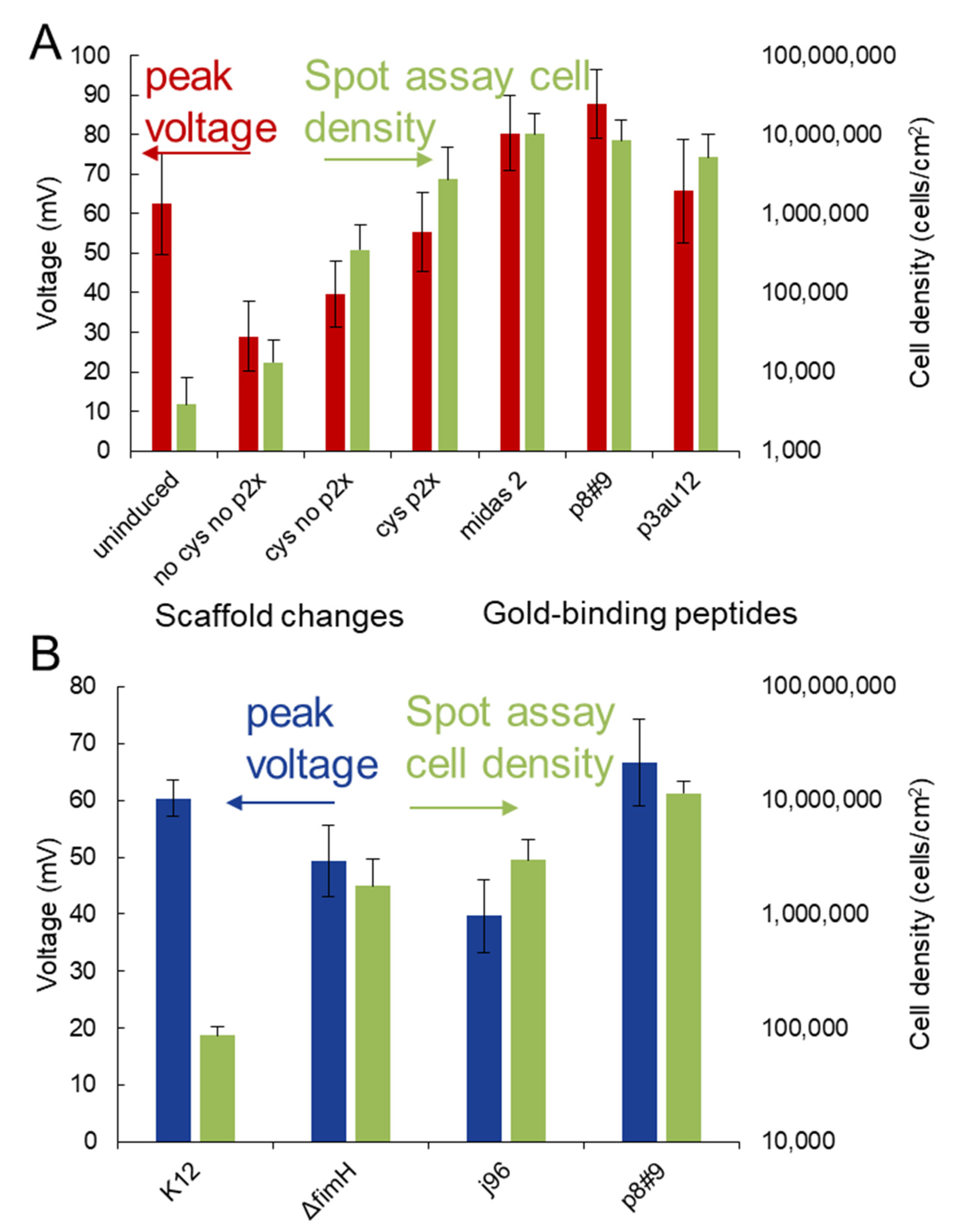
To quantify the relationship between binding affinity and µL-MFC voltage, a range of strains with different affinities for gold were developed for the two scaffolds (eCPX and FimH). The peak voltage obtained in the run was selected as a measure of µL-MFC performance; this peak voltage was typically observed around 1 h, after which the voltage slowly declined to zero over a period of 6–24 h. For the affinity of the strains to a gold substrate, the cells were allowed to attach over a period of 20 min, washed and then imaged with an SEM to obtain the cell density. These results are shown in Figure 3 with Figure 3A showing data for the eCPX scaffold and Figure 3B for the FimH scaffold. Representative SEM images are shown in Figure S2.
For the eCPX scaffold variations examined here, Figure 3A shows the peak voltage on the left axis (red bars) and the binding affinity on the right axis (green bars). The uninduced cells, which do not display the eCPX scaffold, have an average peak voltage of 62 mV while having a low affinity to gold. With the 1 MΩ resistance and an active area of 0.4 cm2, this corresponds to a power of approximately 0.1 mW/m2, similar to the performance of E. coli and other electrogenic organisms in similar setups [48,54,55].
The version of the eCPX scaffold engineered to have minimal affinity to gold (no cys no P2X) has a moderate increase in the binding affinity over the uninduced cells but a large decrease in the peak voltage. The decrease in the peak voltage is likely due to the stress of expressing the eCPX protein. Similar loss of function has been observed in other MFCs displaying large numbers of coat proteins; in S. oneidensis, its ability to reduce riboflavin and Fe(III) decreased when overexpressing LamB as a scaffold gold-binding protein [36]. When the eCPX scaffold is engineered to incorporate a cysteine tag alone or a cysteine tag along with the P2X peptide, the binding affinity and peak voltage both increase. In the case of cysteine and P2X both being incorporated, the binding increases from 13,000 cells/cm2 without cysteine and P2X to 2,700,000 cells/cm2 with P2X and cysteine with a corresponding increase in the peak voltage, from 30 to 55 mV.
Several literature gold-binding peptides were also incorporated into the cys P2X scaffold and all served to increase both the binding affinity and peak voltage of the MFCs, with p8#9 having the largest effect on the peak voltage, increasing it to 88 mV, while p3-Au12 had a smaller effect, both on the voltage and on the binding density. With Midas-2 and p8#9 incorporated, the peak voltages were even moderately higher than the peak voltage of the uninduced cells, which do not have the metabolic costs of displaying the membrane scaffold. When compared with induced cells with no affinity towards gold (no cys, no P2X), a 2.5−3 times increase in voltage is observed, corresponding to an approximately 8 times increase in power.
Overall, when the eCPX scaffold is displayed, a clear relationship is observed between the binding affinity of the cells and the peak voltage in the MFC. The voltage increase may be due, in part, to increased attachment of cells to the electrode surface, although when SEM images were also taken for the gold surfaces after the MFC runs were complete, the cell densities were uniformly high (>1,000,000 cells/cm2). (Figures S3 and S4) Uniform, high cell densities are not surprising under quiescent conditions and may indicate that voltage differences are not only due to changes in cell density on the electrode under operation but are also due to an enhancement of the per cell charge transfer.
To investigate the generality of the consequent voltage increase, a second scaffold, the fimbriae, was engineered to increase bacterial affinity for gold. While this fimbriae scaffold normally adheres strongly to single or multiple mannose residues [56], the affinity for gold was increased by both overexpressing the fimbriae and by incorporating a gold-binding peptide p8#9 along with a histidine tag into the tip protein (FimH) [43]. The affinity and peak voltage of this engineered strain, along with two control strains and an unengineered strain, are shown in Figure 3B. The unengineered strain has a similar peak voltage and somewhat higher binding affinity than the uninduced cells in Figure 3A. Even without the incorporation of a gold-binding peptide, a significant increase in the binding affinity is observed upon overexpression of the fimbriae. This is observed whether the tip protein is expressed (J96) or not expressed (ΔFimH). A slight decrease in peak voltage is observed relative to the unengineered strain, likely due to the increased stress the cells experience associated with overexpression of the fimbriae. When a gold-binding peptide is expressed, both the peak voltage and the binding affinity are increased compared to the control strains. The binding affinity is similar to the strong binders with the eCPX scaffold and the peak voltage is similar to the peak voltage of some of the strong binders, although it is not as high as the best strains in the eCPX scaffold.
Based on the results in the µL-MFCs, a longer operation was examined with 40 mL U-tube MFCs. A schematic of these fuel cells is shown in Figure 4 (inset), with the voltages obtained in these fuel cells over five days of operation shown in the main figure. These MFCs will run for weeks with only modest decreases in power, but peak power is normally reached in a few days when starting from a low cell density. Both scaffolds were characterized in the larger MFCs. Since the strains that contained the p8#9 gold-binding peptide in the two scaffolds produced the highest peak voltage in the µL-MFCs, these strains, along with appropriate controls, were selected for further characterization in the larger, U-tube MFCs.
Cells displaying the FimH scaffold with the p8#9 gold-binding peptide have consistently higher voltages than the unengineered cells across the five day runs. While MFCs with the unengineered cells start with a low voltage (15 mV at 1 day) and gradually increase in voltage to 30 mV by the end of the run, the FimH cells rapidly reach a voltage of 50 mV within one day and then gradually increase in voltage after this, reaching a voltage of 115 mV after 5 days. As would be expected from the µL-MFC runs, MFCs with strains engineered to overexpress the fimbriae without the gold-binding peptide have voltages intermediate between the FimH-p8#9 and the unengineered cells (Figure S5). The voltage differences between the unengineered cells and the FimH-p8#9 cells are larger than observed in the µL-MFCs and likely reflect that in the U-tube MFCs, the bacteria have to grow on and colonize the electrode. This likely allows any advantage the FimH-p8#9 cells have in binding and electron transfer to gold to become enhanced over time.
When cells displaying the p8#9 gold-binding peptide in the cys-P2X eCPX scaffold are used in MFCs, the voltage initially increases in a manner similar to MFCs with FimH-p8#9 cells. At day 1, the voltages are nearly identical and significantly above the control MFCs inoculated with cells not displaying either scaffold. However, after one day the voltage slowly declines in the MFCs inoculated with p8#9 displayed in the cys-P2X eCPX scaffold, reaching the voltage of the K12-inculated MFCs around 2.5 days and, ultimately, declining to half the voltage of these MFCs. Because of differences between the eCPX scaffold strain (MC1061) and the K12 strain used in these experiments (MG1655), uninduced MC1061 MFCs were also tested. Similar to the induced eCPX MFCs at the end of the run, the uninduced MFCs also produce a voltage of approximately half of the K12-inoculated MFCs (Figure S6). Scaffold expression was checked for planktonic cells using YPet binding (Figure S7) and, while expression had declined only slightly at 40 h (1.7 d), when the experiment ends at 144 h (6 d) less than half the cells still displayed the eCPX scaffold. SEM images acquired after the completion of the runs show a high extent of biofilm formation for p8#9 expressed in both the FimH and eCPX scaffolds, and for the control runs as well (Figure S8). However, in regions of lower cell densities, a number of filamentous cells were observed with the eCPX scaffold, which can be indicative of a highly stressed state [57]. The decline in voltage with the eCPX can be attributed to a decline in peptide expression and, perhaps, also to a reduced ability to deal with the stresses of the long-term MFC operation with this strain. Although the eCPX scaffold is not suitable for long-term operation in MFCs, the strong binding from the p8#9 cys-P2X eCPX scaffold does result in an initial increase in voltage similar to the behavior of the p8#9 peptide in the FimH scaffold.
During the U-tube MFC operation, variable resistance sweeps were run periodically with the trends from these tests following the behavior of the constant resistance portions of the runs. Figure 5 shows current versus power plots taken near the beginning (1 day) and end (5 days) of the experiment. At day 1, the two engineered strains have significantly higher power and current densities than the control strain. The internal resistance of the two engineered strains is approximately 5 MΩ, with the control strain having a higher internal resistance of approximately 15 MΩ. In similar U-tube setups with graphite electrodes, internal resistances are typically around 10–100 kΩ [28,58], so the high internal resistances can be attributed to the use of gold electrodes, which, while being a good metal electrode, do not perform as well as carbon based electrodes [59]. The lower internal resistances of the engineered strains likely reflects improved charge transfer between the electrode and the cells. A number of mechanisms may be important; for example, charge transfer to gold electrodes can be improved with more intimate contacts between membrane-bound redox active proteins [34] and the electrode, or changes in gold surface to facilitate electron transfer [32]. At 5 days, power and current densities of MFCs with the FimH strain increased, while those with the eCPX strain decreased to values slightly below the control strains. The internal resistance with the FimH strain also dropped slightly to approximately 2 MΩ while the values for the other strains either increased slightly (eCPX, 12 MΩ), or remained the same (control, 15 MΩ). These changes are consistent with the trends seen for the constant resistance portions of the measurements and likely reflect either improved electrode colonization in the case of the FimH strain, or cell stress and death in the case of the eCPX strain.
Using this genetic engineering approach to control the microbe–electrode interactions produces power increases that compare well to previous efforts to enhance microbe–electrode interactions. Table 1 shows a comparison of the results of this work with previous efforts to either functionalize electrode surfaces to improve biological electron transport or to engineer a microorganism’s interactions with an electrode surface. The 10-foldincrease in power exceeds the enhancement from many electrode modifications, although it is smaller than the best electrode modifications. Our enhancement exceeds previous efforts that used controlled affinity approaches and is comparable to the best previous results that leverage enzyme display.

4. Conclusions

Here, we have investigated how bacteria-surface interactions affect the output of MFCs and have shown that E. coli displaying high affinity gold-binding motifs enhance MFC currents over unengineered cells. This effect was shown to be general to multiple scaffolds, specifically outer membrane coat proteins and in the tip protein of the fimbriae. A clear trend was observed where increased binding affinity resulted in increased electrical power production in µL-MFCs. This effect was observed in two types of MFCs that operate on different time and size scales. In longer (5 day) runs in larger (40 mL) U-tube fuel cells, the cells displaying a gold-binding peptide in the FimH scaffold produced 10 times higher power densities than control cells not engineered for surface binding. Bringing bacteria into stable, close proximity to electrodes to enhance biological electron transfer has been of long-standing interest, and the approach investigated here should enable enhancements in many other bioelectrochemical systems, taking advantage of the many biomolecular scaffolds, genetic circuits and material binding peptides that already exist. Gold electrodes are suitable for sensing and bioelectronics communication due to their stability and facile deposition and patterning. For power generation specifically, the approach developed here could be adapted to lower costs and for higher surface area electrodes that are commonly carbon-based by altering the expression systems to display peptides with appropriate affinities. For both sensing and power generation applications, biofouling frequently creates major challenges and these controlled adhesion approaches may provide handles to address these issues, although the setups used in this work cannot address these questions specifically. Further enhancement in power production may be possible by combining this approach with other methods for enhancing charge transfer. Adding nanoparticles may provide additional current enhancements and there may be benefits from combining controlled adhesion approaches with other genetic engineering approaches to improve charge transfer. As the bacterial membranes are likely to be in close proximity to the electrode surface, this may increase the effectiveness of redox couples introduced into the cell membrane or engineered to be secreted. The peptides used in this study were selected to provide high affinity towards a gold electrode, but material binding peptides also frequently display selectivity for particular materials and binding conditions (including pH) that could be further exploited. The selectivity of material binding peptides should allow the direction of cells to particular surfaces within a device while peptides with affinity only under limited conditions allow a rapid response to environmental variables such as pH. Combining these results with the increasing sophistication of genetic circuits allows linking and triggering of many potential sense and respond actions by the cell with changes at the electrode surface. Finally, the ability to carefully engineer adhesion in many scaffolds should allow interactions to be tuned to the application and, more fundamentally, to help develop a better understanding of how adhesion is implicated in electrogenesis.

Supplementary Materials

The following are available online at https://www.mdpi.com/article/10.3390/en14175389/s1, Figure S1: Photograph of a representative spot assay plate, Figure S2: Representative SEM images taken in the center of the spots, Figure S3: Comparison of the cell density on the anode with cell density in spot assay, Figure S4: Representative SEM images of the µL-MFC anodes after operation, Figure S5: Voltage in U-tube microbial fuel cells held at 1 MΩ and inoculated with FimH strains, Figure S6: Voltage in U-tube microbial fuel cells held at 1 MΩ and inoculated with eCPX scaffold strains, Figure S7: Expression of the eCPX scaffold in planktonic cells taken from running microbial fuel cells, Figure S8: Representative SEM images taken of the anodes after operation of the U-tube microbial fuel cells.

Author Contributions

Conceptualization, J.P.J., D.A.S., J.L.L., D.N.S.-C. and J.J.S.; Investigation, J.P.J., D.A.S. and J.L.L.; Methodology, J.P.J., D.A.S. and J.L.L.; Writing—original draft, J.P.J., D.A.S. and J.L.L.; Writing—review and editing, J.P.J., D.A.S., J.L.L., D.N.S.-C. and J.J.S. All authors have read and agreed to the published version of the manuscript.

Funding

This research received no external funding.

Institutional Review Board Statement

Not applicable.

Informed Consent Statement

Not applicable.

Data Availability Statement

Data is contained within the article or supplementary material.

Acknowledgments

The authors acknowledge Jeffrey Rice for help with developing the gold affinity spot assay, Megan Small for help with the FimH structure in Figure 1, and Margaret Hurley for helpful discussions. J.P.J. and J.L.L. acknowledge support from Oak Ridge Affiliated Universities for their stipends for part of this work via ARL internal funding.

Conflicts of Interest

The authors declare no conflict of interest.

References

  1. Cao, Y.; Feng, Y.; Ryser, M.D.; Zhu, K.; Herschlag, G.; Cao, C.; Marusak, K.; Zauscher, S.; You, L. Programmable assembly of pressure sensors using pattern-forming bacteria. Nat. Biotechnol. 2017, 35, 1087. [Google Scholar] [CrossRef]
  2. Feinberg, A.W. Biological Soft Robotics. Annu. Rev. Biomed. Eng. 2015, 17, 243–265. [Google Scholar] [CrossRef] [PubMed]
  3. Martel, S. Bacterial microsystems and microrobots. Biomed. Microdevices 2012, 14, 1033–1045. [Google Scholar] [CrossRef] [PubMed]
  4. Jahnke, J.P.; Idso, M.N.; Hussain, S.; Junk, M.J.N.; Fsher, J.M.; Phan, D.D.; Han, S.; Chmelka, B.F. Functionally Active Membrane Proteins Incorporated in Mesostructured Silica Films. J. Am. Chem. Soc. 2018, 140, 3892–3906. [Google Scholar] [CrossRef] [PubMed]
  5. Halma, M.; Mousty, C.; Forano, C.; Sancelme, M.; Besse-Hoggan, P.; Prevot, V. Bacteria encapsulated in layered double hydroxides: Towards an efficient bionanohybrid for pollutant degradation. Colloids Surf. B Biointerfaces 2015, 126, 344–350. [Google Scholar] [CrossRef] [PubMed]
  6. Petrova, O.E.; Sauer, K. Sticky situations: Key components that control bacterial surface attachment. J. Bacteriol. 2012, 194, 2413–2425. [Google Scholar] [CrossRef] [PubMed] [Green Version]
  7. Bozovičar, K.; Bratkovič, T. Evolving a Peptide: Library Platforms and Diversification Strategies. Int. J. Mol. Sci. 2020, 21, 2015. [Google Scholar] [CrossRef] [PubMed] [Green Version]
  8. Care, A.; Bergquist, P.L.; Sunna, A. Solid-binding peptides: Smart tools for nanobiotechnology. Trends Biotechnol. 2015, 33, 259–268. [Google Scholar] [CrossRef] [PubMed]
  9. Sanghvi, A.B.; Miller, K.P.H.; Belcher, A.M.; Schmidt, C.E. Biomaterials functionalization using a novel peptide that selectively binds to a conducting polymer. Nat. Mater. 2005, 4, 496. [Google Scholar] [CrossRef]
  10. Brown, S. Metal-recognition by repeating polypeptides. Nat. Biotechnol. 1997, 15, 269. [Google Scholar] [CrossRef]
  11. Adams, B.L.; Hurley, M.M.; Jahnke, J.P.; Stratis-Cullum, D.N. Functional and Selective Bacterial Interfaces Using Cross-Scaffold Gold Binding Peptides. JOM 2015, 67, 2483–2493. [Google Scholar] [CrossRef] [Green Version]
  12. Wang, S.; Humphreys, E.S.; Chung, S.-Y.; Delduco, D.F.; Lustig, S.R.; Wang, H.; Parker, K.N.; Rizzo, N.W.; Subramoney, S.; Chiang, Y.-M.; et al. Peptides with selective affinity for carbon nanotubes. Nat. Mater. 2003, 2, 196. [Google Scholar] [CrossRef]
  13. Naik, R.R.; Stringer, S.J.; Agarwal, G.; Jones, S.E.; Stone, M.O. Biomimetic synthesis and patterning of silver nanoparticles. Nat. Mater. 2002, 1, 169. [Google Scholar] [CrossRef]
  14. Oh, D.; Qi, J.; Lu, Y.-C.; Zhang, Y.; Shao-Horn, Y.; Belcher, A.M. Biologically enhanced cathode design for improved capacity and cycle life for lithium-oxygen batteries. Nat. Commun. 2013, 4, 2756. [Google Scholar] [CrossRef] [Green Version]
  15. Seker, U.O.; Demir, H.V. Material binding peptides for nanotechnology. Molecules 2011, 16, 1426–1451. [Google Scholar] [CrossRef] [PubMed] [Green Version]
  16. So, C.R.; Hayamizu, Y.; Yazici, H.; Gresswell, C.; Khatayevich, D.; Tamerler, C.; Sarikaya, M. Controlling Self-Assembly of Engineered Peptides on Graphite by Rational Mutation. ACS Nano 2012, 6, 1648–1656. [Google Scholar] [CrossRef] [PubMed] [Green Version]
  17. Dong, H.; Sarkes, D.A.; Rice, J.J.; Hurley, M.M.; Fu, A.J.; Stratis-Cullum, D.N. Living Bacteria–Nanoparticle Hybrids Mediated through Surface-Displayed Peptides. Langmuir 2018, 34, 5837–5848. [Google Scholar] [CrossRef]
  18. Du, J.; Catania, C.; Bazan, G.C. Modification of Abiotic–Biotic Interfaces with Small Molecules and Nanomaterials for Improved Bioelectronics. Chem. Mater. 2014, 26, 686–697. [Google Scholar] [CrossRef]
  19. Ross, D.E.; Flynn, J.M.; Baron, D.B.; Gralnick, J.A.; Bond, D.R. Towards electrosynthesis in shewanella: Energetics of reversing the mtr pathway for reductive metabolism. PLoS ONE 2011, 6, e16649. [Google Scholar] [CrossRef] [PubMed]
  20. Logan, B.E.; Wallack, M.J.; Kim, K.-Y.; He, W.; Feng, Y.; Saikaly, P.E. Assessment of Microbial Fuel Cell Configurations and Power Densities. Environ. Sci. Technol. Lett. 2015, 2, 206–214. [Google Scholar] [CrossRef] [Green Version]
  21. Venkata Mohan, S.; Velvizhi, G.; Annie Modestra, J.; Srikanth, S. Microbial fuel cell: Critical factors regulating bio-catalyzed electrochemical process and recent advancements. Renew. Sustain. Energy Rev. 2014, 40, 779–797. [Google Scholar] [CrossRef]
  22. Ali, J.; Wang, L.; Waseem, H.; Sharif, H.M.A.; Djellabi, R.; Zhang, C.; Pan, G. Bioelectrochemical recovery of silver from wastewater with sustainable power generation and its reuse for biofouling mitigation. J. Clean. Prod. 2019, 235, 1425–1437. [Google Scholar] [CrossRef]
  23. Tremblay, P.-L.; Zhang, T. Electrifying microbes for the production of chemicals. Front. Microbiol. 2015, 6, 201. [Google Scholar] [CrossRef] [Green Version]
  24. Tschirhart, T.; Kim, E.; McKay, R.; Ueda, H.; Wu, H.-C.; Pottash, A.E.; Zargar, A.; Negrete, A.; Shiloach, J.; Payne, G.F.; et al. Electronic control of gene expression and cell behaviour in Escherichia coli through redox signalling. Nat. Commun. 2017, 8, 14030. [Google Scholar] [CrossRef] [Green Version]
  25. Terrell, J.L.; Tschirhart, T.; Jahnke, J.P.; Stephens, K.; Liu, Y.; Dong, H.; Hurley, M.M.; Pozo, M.; McKay, R.; Tsao, C.Y.; et al. Bioelectronic control of a microbial community using surface-assembled electrogenetic cells to route signals. Nat. Nanotechnol. 2021, 16, 688–697. [Google Scholar] [CrossRef] [PubMed]
  26. Fraiwan, A.; Choi, S. A stackable, two-chambered, paper-based microbial fuel cell. Biosens. Bioelectron. 2016, 83, 27–32. [Google Scholar] [CrossRef] [Green Version]
  27. Sund, C.; McMasters, S.; Crittenden, S.; Harrell, L.; Sumner, J. Effect of electron mediators on current generation and fermentation in a microbial fuel cell. Appl. Microbiol. Biotechnol. 2007, 76, 561–568. [Google Scholar] [CrossRef]
  28. Garner, L.E.; Park, J.; Dyar, S.M.; Chworos, A.; Sumner, J.J.; Bazan, G.C. Modification of the Optoelectronic Properties of Membranes via Insertion of Amphiphilic Phenylenevinylene Oligoelectrolytes. J. Am. Chem. Soc. 2010, 132, 10042–10052. [Google Scholar] [CrossRef] [PubMed]
  29. Jahnke, J.P.; Dong, H.; Sarkes, D.A.; Sumner, J.J.; Stratis-Cullum, D.N.; Hurley, M.M. Peptide-mediated binding of gold nanoparticles to E. coli for enhanced microbial fuel cell power generation. MRS Commun. 2019, 9, 904–909. [Google Scholar] [CrossRef]
  30. Park, D.H.; Kim, S.K.; Shin, I.H.; Jeong, Y.J. Electricity production in biofuel cell using modified graphite electrode with Neutral Red. Biotechnol. Lett. 2000, 22, 1301–1304. [Google Scholar] [CrossRef]
  31. Popov, A.L.; Kim, J.R.; Dinsdale, R.M.; Esteves, S.R.; Guwy, A.J.; Premier, G.C. The effect of physico-chemically immobilized methylene blue and neutral red on the anode of microbial fuel cell. Biotechnol. Bioprocess Eng. 2012, 17, 361–370. [Google Scholar] [CrossRef]
  32. Crittenden, S.R.; Sund, C.J.; Sumner, J.J. Mediating Electron Transfer from Bacteria to a Gold Electrode via a Self-Assembled Monolayer. Langmuir 2006, 22, 9473–9476. [Google Scholar] [CrossRef] [PubMed]
  33. Yong, Y.-C.; Dong, X.-C.; Chan-Park, M.B.; Song, H.; Chen, P. Macroporous and Monolithic Anode Based on Polyaniline Hybridized Three-Dimensional Graphene for High-Performance Microbial Fuel Cells. ACS Nano 2012, 6, 2394–2400. [Google Scholar] [CrossRef]
  34. Amir, L.; Carnally, S.A.; Rayo, J.; Rosenne, S.; Melamed Yerushalmi, S.; Schlesinger, O.; Meijler, M.M.; Alfonta, L. Surface Display of a Redox Enzyme and its Site-Specific Wiring to Gold Electrodes. J. Am. Chem. Soc. 2013, 135, 70–73. [Google Scholar] [CrossRef] [PubMed]
  35. Jensen, H.M.; Albers, A.E.; Malley, K.R.; Londer, Y.Y.; Cohen, B.E.; Helms, B.A.; Weigele, P.; Groves, J.T.; Ajo-Franklin, C.M. Engineering of a synthetic electron conduit in living cells. Proc. Natl. Acad. Sci. USA 2010, 107, 19213. [Google Scholar] [CrossRef] [PubMed] [Green Version]
  36. Kane, A.L.; Bond, D.R.; Gralnick, J.A. Electrochemical Analysis of Shewanella oneidensis Engineered to Bind Gold Electrodes. ACS Synth. Biol. 2013, 2, 93–101. [Google Scholar] [CrossRef]
  37. Causa, F.; Della Moglie, R.; Iaccino, E.; Mimmi, S.; Marasco, D.; Scognamiglio, P.L.; Battista, E.; Palmieri, C.; Cosenza, C.; Sanguigno, L.; et al. Evolutionary screening and adsorption behavior of engineered M13 bacteriophage and derived dodecapeptide for selective decoration of gold interfaces. J. Colloid Interface Sci. 2013, 389, 220–229. [Google Scholar] [CrossRef]
  38. Kim, J.; Rheem, Y.; Yoo, B.; Chong, Y.; Bozhilov, K.N.; Kim, D.; Sadowsky, M.J.; Hur, H.-G.; Myung, N.V. Peptide-mediated shape- and size-tunable synthesis of gold nanostructures. Acta Biomater. 2010, 6, 2681–2689. [Google Scholar] [CrossRef]
  39. Huang, Y.; Chiang, C.-Y.; Lee, S.K.; Gao, Y.; Hu, E.L.; Yoreo, J.D.; Belcher, A.M. Programmable Assembly of Nanoarchitectures Using Genetically Engineered Viruses. Nano Lett. 2005, 5, 1429–1434. [Google Scholar] [CrossRef]
  40. Nam, K.T.; Kim, D.-W.; Yoo, P.J.; Chiang, C.-Y.; Meethong, N.; Hammond, P.T.; Chiang, Y.-M.; Belcher, A.M. Virus-Enabled Synthesis and Assembly of Nanowires for Lithium Ion Battery Electrodes. Science 2006, 312, 885–888. [Google Scholar] [CrossRef] [PubMed] [Green Version]
  41. Rice, J.J.; Schohn, A.; Bessette, P.H.; Boulware, K.T.; Daugherty, P.S. Bacterial display using circularly permuted outer membrane protein OmpX yields high affinity peptide ligands. Protein Sci. 2006, 15, 825–836. [Google Scholar] [CrossRef]
  42. Rice, J.J.; Daugherty, P.S. Directed evolution of a biterminal bacterial display scaffold enhances the display of diverse peptides. Protein Eng. Des. Sel. 2008, 21, 435–442. [Google Scholar] [CrossRef] [PubMed] [Green Version]
  43. Terrell, J.L.; Dong, H.; Holthoff, E.L.; Small, M.C.; Sarkes, D.A.; Hurley, M.M.; Stratis-Cullum, D.N. Investigation of engineered bacterial adhesins for opportunity to interface cells with abiotic materials. In Proceedings of the Smart Biomedical and Physiological Sensor Technology XIII, Baltimore, MD, USA, 17–21 April 2016; p. 986308. [Google Scholar]
  44. Adams, B.L.; Finch, A.S.; Hurley, M.M.; Sarkes, D.A.; Stratis-Cullum, D.N. Genetically Engineered Peptides for Inorganics: Study of an Unconstrained Bacterial Display Technology and Bulk Aluminum Alloy. Adv. Mater. 2013, 25, 4585–4591. [Google Scholar] [CrossRef] [PubMed] [Green Version]
  45. Blomfjeld, I.C.; McClain, M.S.; Eisenstein, B.I. Type 1 fimbriae mutants of Escherichia coli K12: Characterization of recognized afimbriate strains and construction of new fim deletion mutants. Mol. Microbiol. 1991, 5, 1439–1445. [Google Scholar] [CrossRef] [PubMed] [Green Version]
  46. Sokurenko, E.V.; Chesnokova, V.; Doyle, R.J.; Hasty, D.L. Diversity of the Escherichia coli type 1 fimbrial lectin. Differential binding to mannosides and uroepithelial cells. J. Biol. Chem. 1997, 272, 17880–17886. [Google Scholar] [CrossRef] [PubMed] [Green Version]
  47. Klemm, P.; Jørgensen, B.J.; van Die, I.; de Ree, H.; Bergmans, H. The fim genes responsible for synthesis of type 1 fimbriae in Escherichia coli, cloning and genetic organization. Mol. Gen. Genet. MGG 1985, 199, 410–414. [Google Scholar] [CrossRef] [PubMed]
  48. Hou, H.; Li, L.; Cho, Y.; de Figueiredo, P.; Han, A. Microfabricated Microbial Fuel Cell Arrays Reveal Electrochemically Active Microbes. PLoS ONE 2009, 4, e6570. [Google Scholar] [CrossRef]
  49. Sund, C.J.; Wong, M.S.; Sumner, J.J. Mitigation of the effect of catholyte contamination in microbial fuel cells using a wicking air cathode. Biosens. Bioelectron. 2009, 24, 3144–3147. [Google Scholar] [CrossRef]
  50. Sarkes, D.A.; Jahnke, J.P.; Stratis-Cullum, D.N. Semi-automated Biopanning of Bacterial Display Libraries for Peptide Affinity Reagent Discovery and Analysis of Resulting Isolates. JoVE 2017, e56061. [Google Scholar] [CrossRef] [Green Version]
  51. Singh, A.; Arya, S.K.; Glass, N.; Hanifi-Moghaddam, P.; Naidoo, R.; Szymanski, C.M.; Tanha, J.; Evoy, S. Bacteriophage tailspike proteins as molecular probes for sensitive and selective bacterial detection. Biosens. Bioelectron. 2010, 26, 131–138. [Google Scholar] [CrossRef]
  52. Hong, N.; Cheng, L.; Wei, B.; Chen, C.; He, L.L.; Kong, D.; Ceng, J.; Cui, H.-F.; Fan, H. An electrochemical DNA sensor without electrode pre-modification. Biosens. Bioelectron. 2017, 91, 110–114. [Google Scholar] [CrossRef] [Green Version]
  53. Choi, S. Microscale microbial fuel cells: Advances and challenges. Biosens. Bioelectron. 2015, 69, 8–25. [Google Scholar] [CrossRef] [PubMed]
  54. Hou, H.; Chen, X.; Thomas, A.W.; Catania, C.; Kirchhofer, N.D.; Garner, L.E.; Han, A.; Bazan, G.C. Conjugated Oligoelectrolytes Increase Power Generation in E. coli Microbial Fuel Cells. Adv. Mater. 2013, 25, 1593–1597. [Google Scholar] [CrossRef]
  55. Hou, H.; Li, L.; Ceylan, C.U.; Haynes, A.; Cope, J.; Wilkinson, H.H.; Erbay, C.; de Figueiredo, P.; Han, A. A microfluidic microbial fuel cell array that supports long-term multiplexed analyses of electricigens. Lab Chip 2012, 12, 4151–4159. [Google Scholar] [CrossRef] [PubMed]
  56. Jahnke, J.; Terrell, J.; Smith, A.; Cheng, X.; Stratis-Cullum, D. Influences of Adhesion Variability on the “Living” Dynamics of Filamentous Bacteria in Microfluidic Channels. Molecules 2016, 21, 985. [Google Scholar] [CrossRef] [PubMed]
  57. Wehrens, M.; Ershov, D.; Rozendaal, R.; Walker, N.; Schultz, D.; Kishony, R.; Levin, P.A.; Tans, S.J. Size Laws and Division Ring Dynamics in Filamentous Escherichia coli cells. Curr. Biol. 2018, 28, 972–979.e5. [Google Scholar] [CrossRef] [PubMed] [Green Version]
  58. Wang, V.B.; Du, J.; Chen, X.; Thomas, A.W.; Kirchhofer, N.D.; Garner, L.E.; Maw, M.T.; Poh, W.H.; Hinks, J.; Wuertz, S.; et al. Improving charge collection in Escherichia coli-carbon electrode devices with conjugated oligoelectrolytes. Phys. Chem. Chem. Phys. 2013, 15, 5867–5872. [Google Scholar] [CrossRef] [PubMed]
  59. Sonawane, J.M.; Yadav, A.; Ghosh, P.C.; Adeloju, S.B. Recent advances in the development and utilization of modern anode materials for high performance microbial fuel cells. Biosens. Bioelectron. 2017, 90, 558–576. [Google Scholar] [CrossRef]
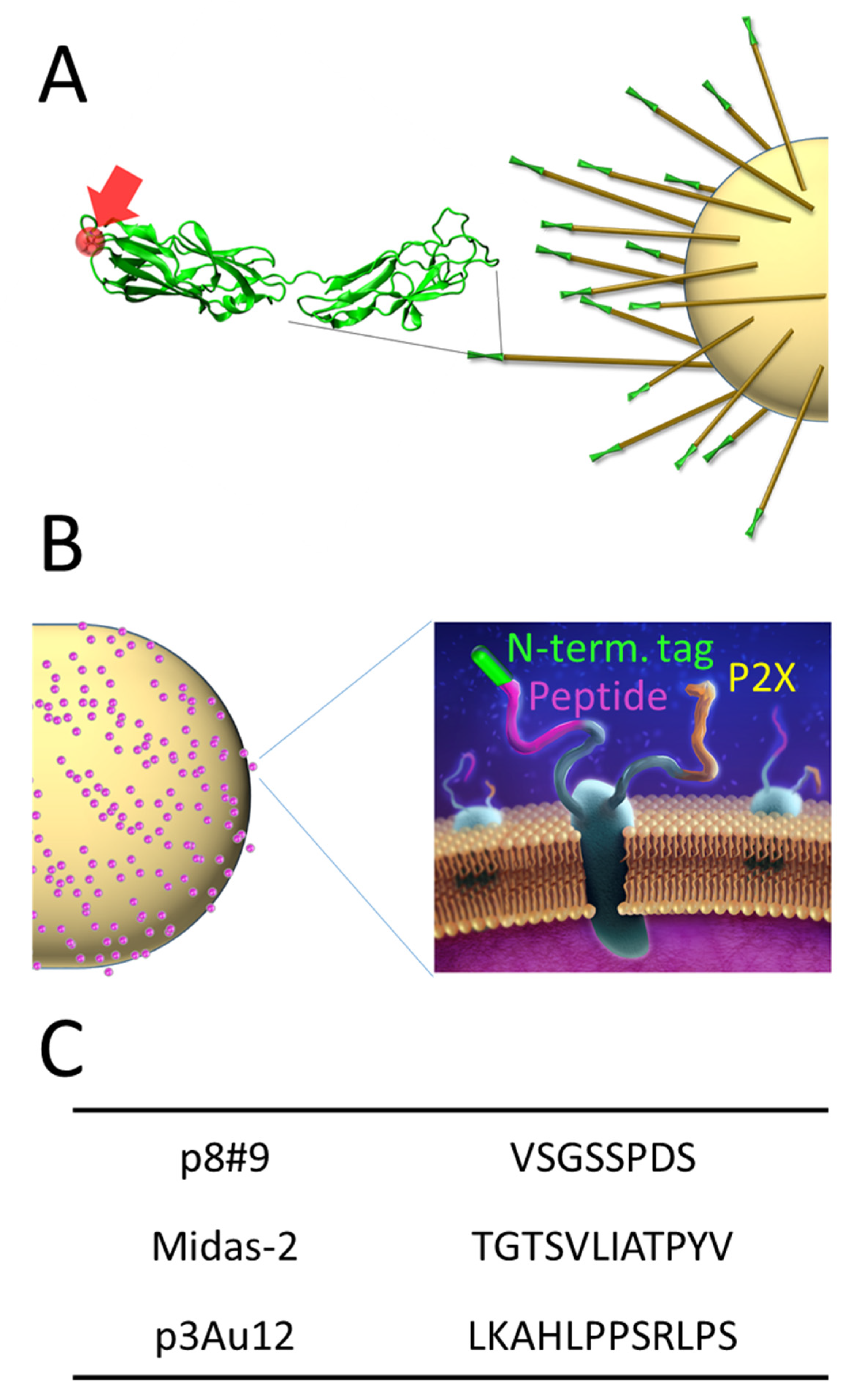
Figure 1. Schematic of the two scaffolds used for controlling the affinity of E. coli towards gold substrate, FimH (A) and eCPX (B). The peptide insertion site in FimH is shown by the red arrow and ball. In eCPX, the peptide location is shown in purple, while the P2X is shown in yellow and the end tag that can be functionalized with cysteine shown in green. (C) Gold binding peptides taken from the literature for use in these experiments.
Energies 14 05389 g001
Figure 2. (A) Schematic of the microliter MFC showing its microbe containing anode compartment and its cathode compartment containing K3Fe(CN)6 as the electron acceptor. (B) Typical voltage traces for MFCs run with a 1 MΩ resistor. After a short startup period the voltage reaches a steady-state and then gradually decreases. Cells displaying gold-binding peptides such as Midas-2 typically reach higher voltages than uninduced cells not displaying any scaffold while heat-killed cells produce a low voltage then quickly decay towards zero.
Energies 14 05389 g002
Figure 3. Peak voltages obtained with μL MFCs running at 1 MΩ (left axes, red or blue bars) and cell densities in a binding assay on a gold surface (right axes, green bars). (A) Data for cells containing the eCPX scaffold, either uninduced or displaying different versions of the eCPX scaffold; cells displaying literature peptides are in the cys P2X scaffold. (B) Data for cells displaying the fimbriae scaffold with and without the FimH tip protein functionalized with the p8#9 gold-binding peptide. The error bars show the standard error (n ≥ 4 for MFCs, n = 3 for cell density).
Energies 14 05389 g003
Figure 4. Voltage in U-tube microbial fuel cells (schematically shown inset) held at 1 MΩ and inoculated with cells displaying either the p8#9 peptide on other the eCPX or FimH scaffold, or lacking either scaffold altogether (labeled K12). The shaded regions show one standard error away from the average calculated from multiple runs (n = 3 FimH, n = 2 K12, eCPX). Cells displaying eCPX and FimH outperform the K12 cells within the first day and the FimH scaffold cells continue to produce higher voltages throughout the experiment.
Energies 14 05389 g004
Figure 5. Variable resistance data at 1 day (A) and 5 days (B) for the same runs as shown in Figure 4. The 1 day data is shown grayed (faded?) out in B for comparison. At 1 day, cells displaying p8#9 in the FimH and eCPX have similar power and current densities, which are 3–5 times higher than the power densities achieved with the K12 control. At 5 days the power density with the FimH scaffold and with the K12 control have increased by a factor of 3, while the power density with the eCPX scaffold has declined. The error bars show 1 standard deviation away from the mean.
Energies 14 05389 g005
Table 1. Comparison of the power density increase for the best results in this work with some previous efforts.
PaperApproachElectrodeEnhancement
[29]Gold-binding peptide + nanoparticlesgold(111) surface4.0
[30]Redox mediator (Neutral Red) immobilized on electrodeGraphite4.8
[31]Redox mediator (Methylene Blue) immobilized on electrodecarbon felt2.1
[33]Conductive Polymer (PANI)carbon cloth2.0
carbon felt13
nickel foam3.2
graphene foam60
[34]Enzyme engineering & gold nanoparticlesGold8.0
[36]Gold-binding peptidegold(111) surface1.4
This workGold-binding peptidegold wire10
Publisher’s Note: MDPI stays neutral with regard to jurisdictional claims in published maps and institutional affiliations.