1. Introduction
Emission regulations for marine diesel engines are increasingly stringent [
1]. The high-pressure common rail system is one of the main measures taken to purify marine diesel engines [
2]. The control strategy for the high-pressure common rail system requires the control system to maintain high and stable rail pressure, and to simultaneously control the timing and amount of injection [
3]. In the control strategy verification, a controlled object is needed to verify the effect of the strategy. The controlled object could be a diesel engine test bench, or a real-time simulation of the diesel engine [
4]. Due to the higher power of single-cylinder marine diesel engines, there is more fuel injection per cycle. At the same time, some tests may introduce risks to the operation of diesel engines and damage the diesel engines [
5]. Therefore, real-time simulation model as the controlled object has become an effective, safe, and low-cost method [
6,
7].
At present, there are few studies of the real-time simulation of the high-pressure common rail system for control, and the related research mainly focuses on two aspects. On the one hand, it is a real-time simulation of the diesel engine for control. The average model is quasi-linear, and it is widely used in the real-time simulation of diesel engines, due to its high calculation accuracy and fast operational speed [
8]. For example, Jianwei et al. used the average method to establish a real-time simulation of diesel engines, to verify the effect of the control system on a turbocharged diesel engine [
9]. Fadila et al. analyzed the effect of a multiple injection control strategy on the temperature and HC emissions, after establishing the average model of a diesel engine [
10]. Tang et al. also used the average model to predict the overall performance of diesel engines [
11]. Wang et al. created real-time simulations of diesel engines by using a method based on the average model and cylinder movement, with their established real-time simulation able to receive signals such as crank angle and exhaust valve lift from the ECU [
12]. On the other hand, the research on the modeling of the high-pressure common rail systems is mainly used to study the characteristics of the system itself. For example, Hiroshi et al. used the optimized a finite element model to analyze the flow and pressure effect in the common rail during single and multiple fuel injection [
13]. Beiererer et al. used a simulation of the common rail system, established by GT-FUEL software, to investigate the effect of structural parameters (such as the length and diameter of high-pressure tubing) on the pressure fluctuation at the inlet of the injector [
14]. According to the research of such scholars, a simulation of high-pressure common rail systems is typically used to study the characteristics of the high-pressure common rail system itself [
15], to optimize structural parameters, or to reduce the fluctuation of common rail pressure [
16], whereas a real-time simulation for control most often models the entire diesel engine. In the real-time simulation of the whole diesel engine, a simulation of the complex high-pressure common rail system is generally not established [
17,
18]. The current research content is more inclined to in-cylinder combustion [
19], emission prediction [
20], or in-cylinder pressure calculation [
11]. Therefore, in order to provide a controlled object for the development of a high-pressure common rail electronic control system of marine diesel engines, it is necessary to study the real-time simulation of the high-pressure common rail system.
The contribution of this paper is to establish a real-time simulation model of a marine diesel engine high-pressure common rail system, provide controlled objects for the development of marine diesel engine control systems, reduce development costs, and reduce potential safety hazards. In general, using the idea of the surrogate model, the real-time simulation model can reduce the amount of calculation required and ensure high accuracy, and the error is less than 5%. The established real-time simulation model can receive the fuel injection duration, fuel injection timing, and engine speed signals from ECU, and can calculate the fuel injection quantity and rail pressure fluctuation in the system. We use the modular modeling method to divide the system into high-pressure oil pump modules, injector modules, and common rail modules. At the same time, considering the influence of temperature on fuel pressure, we also design a mass calculation module to facilitate the transmission and observation of calculation quantity. The main function of the common rail pipe module is to calculate the common rail pressure and simulate the rail pressure fluctuation, according to the outflow and inflow of fuel. The high-pressure oil pump module can receive the speed signal from ECU and the opening of the proportional valve, calculate the fuel supply, and transmit it to the common rail pipe. According to the fuel injection control signal provided by ECU and the actual situation. The fuel injector module can calculate the fuel injection quantity, the fuel return quantity of the fuel injector control chamber and the leakage quantity. On the whole, the real-time simulation model can ensure that the injection error is less than 5%, and can simulate the rail pressure fluctuation. Additionally, it can respond to different rail pressure control strategies. The developed real-time simulation of the marine high-pressure common rail fuel system can provide controlled simulation objects for the closed-loop testing of fuel injection and the rail pressure regulation functions of the electronic control system, as well as provide technical support for further improving the integrity of the function of the real-time simulation of marine diesel engine.
2. Framework of Real-Time Simulation for a High-Pressure Common Rail System
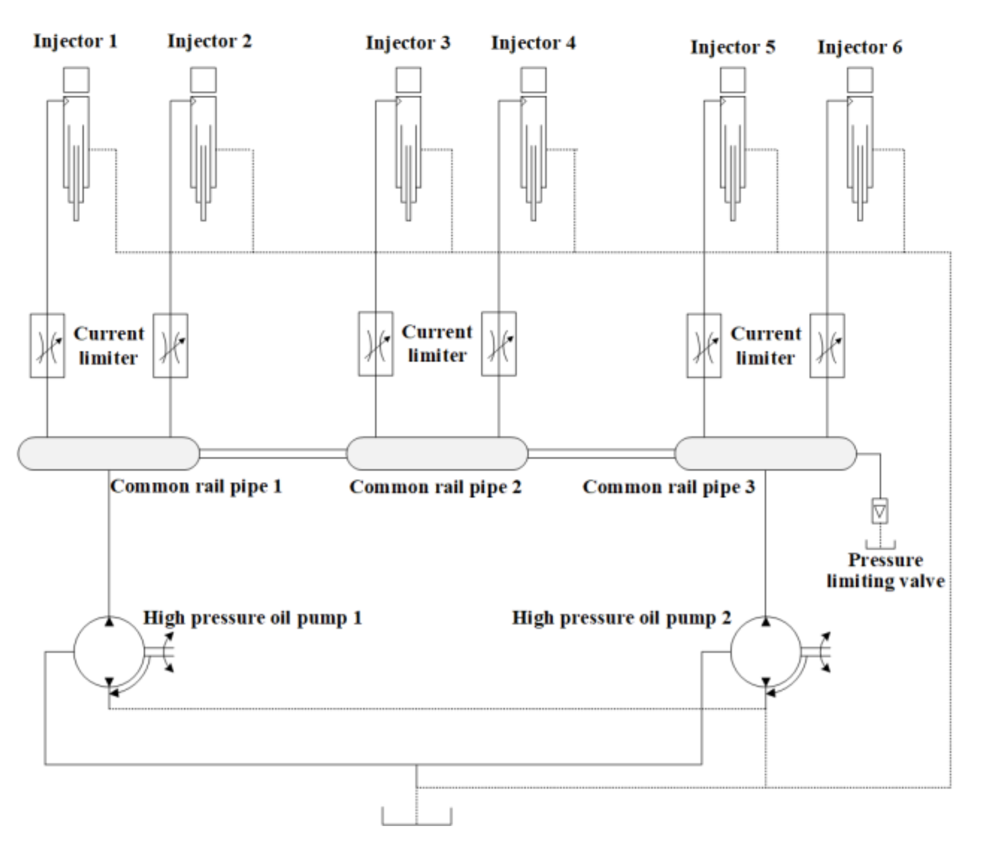
In this paper, a marine high-pressure common rail fuel system is taken as the simulation object, with its overall structure shown in
Figure 1. The main structure is expressed in
Figure 1, with reference to the actual mechanical structure [
5]. The high-pressure common rail system uses a distributed common rail system with two high-pressure oil pumps, and three common rail pipes supplied with six injectors.
The real-time model is designed according to the actual structure. The real-time simulation of the whole system comprises the high-pressure oil pump, common rail pipe, injector, and mass conversion. According to the structure and working principles of the marine high-pressure common rail system, the overall development framework is shown in
Figure 2.
Based on the flow direction, the control system provides the proportional valve opening signal and the diesel engine speed signal to the pump submodel in the real-time model, while the high-pressure oil pump submodel provides the supply signal to the pipe model. The common rail pipe model calculates the current rail pressure and transmits it to the injector submodel, according to the fuel supply signal from the high-pressure oil pump submodel, the fuel consumption from the mass conversion submodel, and the diesel temperature signal from the temperature calculation model.
The injector submodel receives the rail pressure signal from the common rail tube model, and the fuel duration and injection timing signal from the ECU. It then queries the MAP data to obtain the fuel consumption, which is transmitted to the mass calculation submodel. The mass calculation submodel simplifies the fuel consumption per cycle from the injector submodel to a piecewise function to calculate the injection rate of the injector as it changes over time. It measures the fuel consumption in the pipe at different times, and outputs it to the pipe submodel for pressure wave calculation. In order to meet the real-time requirements, a large number of characteristic data about the high-pressure common rail system are needed to establish the injector and the high-pressure oil pump submodels. Since the required data are too large, and some of the data are transitional and condition data, it is difficult to obtain them through bench testing. Therefore, this paper first establishes the simulation performance of the high-pressure common rail system by using test bench data, and provides the obtained data to the injector and the pump submodels. Finally, the establishment of the real-time simulation is completed. The modeling logic diagram is shown in
Figure 3.
3. Determination of the Simulation Performance of the High-Pressure Common Rail System
As with the establishment of the real-time simulation of the high-pressure common rail system, the development of the injector and the high-pressure oil pump submodels requires a large number of characteristic data, with most of the data for transition conditions being difficult to obtain through bench testing. At the same time, in order to reduce the development cost, the performance of the high-pressure common rail system was first established to provide characteristic data for the real-time simulation of the high-pressure common rail system. The performance simulation of the high-pressure common rail fuel system is established using the AMESim platform shown in
Figure 4.
According to the actual structure and working principles of a high-pressure common rail system, the simulation model of a high-pressure common rail system is developed using AMESim software, which is based on mechanical-electronic-hydraulic principles. The whole simulation model is composed of a fuel injector, fuel pump, high-pressure common rail, and high-pressure oil pipe.
In this paper, the high-pressure oil pump model is designed in three parts, the high-pressure oil pump body, the inlet and outlet ball valve, and the proportional solenoid valve. In the construction of the proportional valve, it is assumed that the oil supply source is a constant pressure oil source to simplify the model. In order to transform the control signal into the power signal, the solenoid valve module is designed in the proportional valve to convert the signal, and the fluid pipeline module is designed considering the compressibility of oil, the pipeline friction, and liquid inertia.
In order to simulate the pressure change caused by the variable volume in the process of fuel injector modeling, a volume module is designed, and the fuel flow and volume value into the cavity are used as inputs to calculate the pressure change of the cavity. At the same time, the throttling effect, before the volume chamber of the inlet ball valve of the solenoid valve assembly, is regarded as a fixed throttling hole to simplify the model.
In the modeling of the high-pressure common rail, considering the pressure transfer in the common rail, the “CFD-1D Pipes” module was adopted to build the common rail. The pressure limiting valve is set to a specific value. When the pressure value in the common rail pipe exceeds the set value, the pressure limiting valve will be opened for oil spill and oil return to limit the amount of higher pressure in the common rail pipe.
As a complex system, the high-pressure common rail system contains hydraulic, mechanical, and electronic control, as well as other aspects of the impact. It is difficult to consider all of the actual factors in the process of establishing the simulation. It is necessary to combine the research focus and make some assumptions about the simulation of a common rail fuel system: (1) A single injection process, assuming that the temperature of the whole common rail system is constant, without the relevant thermodynamic calculations. (2) The plunger cavity, needle valve cavity, and control cavity are treated with concentrated volume, and the hydraulic connection of most parts is connected with the concentrated volume model. (3) Not considering the elastic deformation of high-pressure system parts. (4) The working process of the solenoid valve of the electronically controlled injector in the common rail system is simplified as a mechanical model, and the change of the current in the solenoid valve is ignored. (5) The oil supply source of the common rail system is assumed to be a constant pressure source.
The simulation data of the performance simulation of the high-pressure common rail system are used to compare and analyze the data from the test bench of the high-pressure common rail fuel injection system, and to verify the mass under different rail pressures and injection durations. Based on similar research, we aimed to set the error below 5% [
5,
21]. The results are shown in
Figure 5 and
Table 1, where the maximum error is less than 5%.
The common rail pressure fluctuation in a high-pressure common rail fuel is simultaneously verified. Taking the rail pressure fluctuation of a common rail system with a cam speed of 500 r/min, common rail pressure of 140 MPa, and an injection pulse width of 2.8 ms as an example, the simulation results of common rail pressure fluctuation are compared with the experimental results shown in
Figure 6. The simulation results are in good agreement with the experimental data, with errors all within 5%. Therefore, it can be considered that the performance model of the high-pressure common rail fuel system can simulate the pressure effect in a common rail pipe, and can provide the process data for the real-time simulation.
4. Establishment of the Real-Time Model of the High-Pressure Common Rail System
4.1. Principles of the Real-Time Simulation Creation
According to the actual working principles behind the high-pressure common rail system, the whole system is divided into a pump submodel, common rail pipe submodel, injector submodel, temperature calculation submodel, and a mass calculation submodel. The real-time simulation is designed with the fuel flow direction as the clue. The high-pressure oil pump submodel receives the proportional valve opening signal and the current engine speed value provided by the control system. The fuel supply is obtained through simulation calculation, and the fuel supply signal is transmitted to the common rail pipe model. The pressure is calculated by the fuel consumption of the fuel supply, the mass from the high-pressure oil pump submodel, and the temperature signal of the temperature calculation submodel. The common rail pressure is transmitted to the injector submodel. According to the data provided by the performance simulation, the injector submodel can receive the fuel injection timing and the fuel injection duration signal provided by the control system. The fuel injection quantity for combustion, the fuel return in the control chamber, and the leakage are designed according to the actual situation obtained. The calculation logic of each model is designed according to the actual working principle of each submodel.
4.2. Fuel Injector Submodel
Based on the working principle and actual working situation of the electronically controlled injector, the injector will first consume the fuel in the pipe, as per the normal injection process. The second part of the fuel flows back to the low-pressure oil circuit, used for solenoid valve opening, and also consumes the fuel in the common rail tube. Moreover, there is a matching gap in the injector, meaning there will be a small amount of leakage during an injection with high-pressure. According to the actual work of the injector, there are three fuel design quantities: first, normal fuel injection; second, open the solenoid valve to control the amount of oil returned; third, leakage is designed according to the actual situation. The total fuel consumption can be simplified to form
In the equation, is the total fuel consumption of the injector, g/H. is the amount of injector fuel, g/H. is the injector leakage, g/H. is the oil return of the injector control chamber, g/H.
The fuel injection volume of the injector, the fuel return volume of the injector control chamber, and the leakage volume of the injector are related to the fuel injection duration, and the common rail pressure signals are all received by the injector. Therefore, in the design of the injector submodel, the query MAP data method is used to calculate the working condition data. The injector submodel receives the fuel injection duration signal from the control system, and the common rail pressure signal from the common rail pipe submodel. The simulated working condition data are queried to obtain the three values of fuel injection volume, fuel return volume, and leakage volume. Since the value calculated in the characteristic simulation is the fuel consumption for each cycle, the injector submodel is connected to the quality conversion submodel. In this paper, the oil return amount used to control the injection action in the control chamber is considered, and the leakage amount is designed according to the sealing condition of the actual structure. They are not the amount of fuel injected into the cylinder by the injector, but they consume the fuel that is in the common rail. The injector submodel transfers the three values of fuel injection, return, and leakage to the quality conversion submodel, and converts them into a fuel consumption rate over time. The development process of the injector submodel is shown in
Figure 7.
The required data regarding the three fuel consumptions are calculated by the developed high-pressure common rail system performance simulation, as shown in
Figure 8,
Figure 9 and
Figure 10.
4.3. High-Pressure Oil Pump Submodel
The high-pressure oil pump adopts a way of changing the opening of the proportional valve to control the output flow of the pump. It can adjust the throttle area, so as to completely control the pressure. In the working process of the high-pressure fuel pump, the calculation of the fuel supply involves the balance calculation of the plunger cavity, the flow calculation of the ball valve, and the calculation of the proportional valve. The general calculation process can ignore the internal fuel working process of the high-pressure fuel pump, and only consider the output flow of the high-pressure fuel pump, simplifying the average fuel supply of the high-pressure fuel pump to the Equation (2).
In the equation: Fuel is the flow rate of the high-pressure oil pump, . is the maximum rate for the high-pressure oil pump, . is the camshaft angular velocity, . is the stroke of the plunger cavity, . is the cross-sectional area of the plunger cavity, . is the number of plungers. is the output back pressure of a high-pressure oil pump, 0.1 . is the inlet pressure of the pump, 0.1 . is the volumetric elastic modulus of fuel, . is the flow proportional coefficient of the proportional valve at different openings.
Equation (2) shows that the output flow of the high-pressure oil pump is mainly affected by three factors: proportional valve opening, high-pressure fuel pump backpressure, and camshaft speed. When the engine speed is constant, the fuel delivery of the high-pressure oil pump is affected by the opening of the proportional valve and the outlet back pressure. According to the engine performance simulation established above, the characteristic data of the high-pressure oil pump can be obtained with the opening of the proportional valve and the outlet back pressure as independent variables, and the fuel delivery as the dependent variable. Moreover, the maximum energy provided by the current engine speed to the high-pressure oil pump is the maximum fuel delivery. Therefore, the value obtained from the characteristic data should be compared with the maximum value provided by the current speed, and the minimum value should be taken. The volume flow value of fuel can then be obtained, because the subsequent calculation requires the mass flow value, meaning the volume flow should be converted into mass flow in the high-pressure oil pump submodel, requiring the current diesel density value. Diesel density is affected by pressure and temperature, meaning the diesel density value can be obtained according to the current diesel temperature and the common rail pressure, allowing the diesel mass flow provided by the high-pressure oil pump submodel to be calculated. This process is shown in
Figure 11. The output flow of the high-pressure oil pump is mainly affected by three factors: proportional valve opening, rail pressure, and camshaft speed. Since the whole MAP has three inputs, it is difficult to list them all. The research object of this paper is the marine medium-speed diesel engine, for which the rated speed is 1000 r/min, and its engine starting is in the low-speed range. Therefore, this paper chooses the diesel engine speed of 1000 r/min and 500 r/min (specifically, a high-pressure oil pump camshaft speed of 500 r/min and 250 r/min under the high-pressure fuel pump fuel supply characteristics data) as an example, as shown in
Figure 12. The indexing value of the engine speed is 100 r/min, and the intermediate matrix is interpolated.
4.4. Common Rail Pipe Submodel
The common rail pipe is simplified as a zero-dimensional cavity, and the modeling of the pressure in the common rail pipe is carried out through mathematical function calculation. The compressibility of the fuel is the main consideration. According to the fluid hydraulic performance of the fuel, the variation formula of the fuel pressure in the pipe can be obtained as shown in Equation (3):
In the equation, is the elastic modulus of the fuel used, . is the pressure in a common rail pipe, . is the volume value of the pipe, . is the density of fuel in the common rail, . is a high-pressure pump’s input fuel mass, . is the fuel quality consumed by the injector, .
The amount of diesel flowing into the common rail pipe comes from the high-pressure oil pump model. The amount of diesel flowing out of the common rail pipe is the total consumption calculated by the injector model. The density of diesel is the same as that of the pump module. Since the unit calculated by the injector model in calculating the injection amount is the injection mass of each stroke, the amount of diesel consumed per unit time should be multiplied by the current engine speed. The process is designed as shown in
Figure 13.
4.5. Submodel of Temperature Calculation
The influence of different initial fuel temperatures on different components can be investigated using a fuel thermal simulation of the system. The temperature has an effect on the rail pressure of the systems. The fuel injection volume, caused by the fuel temperature, changes greatly at low pressure, and the injection volume, caused by fuel temperature, changes little at a high common rail pressure.
In order to simplify the calculation of the fuel temperature in real-time, the main sources of simplified fuel temperature change are high-pressure fuel compression and ambient temperature heat transfer. The fuel temperature change caused by heat transfer mainly comes from the combustion chamber temperature and the cooling water temperature, which simplifies the friction heat generation, and the convective heat transfer of fuel with the shell. The cooling water temperature and the combustion temperature are set to calculate the proportion, and the heat transfer temperature is calculated by weighted average. If the weight coefficient of the combustion temperature is set to the weight of combustion, the water temperature is (1-a). The calculation is as follows:
In the equation: is heat transfer increasing temperature, . is the cylinder temperature weight, 1. is the cylinder temperature, and . is the ambient temperature, .
The temperature change caused by pressurization is determined by looking at a one-dimensional table. The independent variable is the current pressure of diesel, and the pressure calculated by the current common rail model is used. The final diesel temperature is obtained by adding the heat transfer temperature and the pressurization temperature. The development process is shown in
Figure 14.
4.6. Submodel of Mass Calculation
In the process of injection, the general injection rate curve is shown in
Figure 15. In order to reduce the calculation time of the simulation, the fuel injection process of the whole injector can be divided into three stages: the beginning of the injection mass, the stability of the injection mass, and the closure of the injection mass. The beginning of the injection mass and the closure of the injection mass can be realized by piecewise function, and the stability of the injection mass is simplified by a fixed number so that the injection flow curve of the injector is simplified as a piecewise function. Under the premise of ensuring that the overall injection quality is unchanged, the data fluctuation of the injection rate curve is simplified.
The mass calculation model mainly calculates the fuel injection rate of the injector, changing over time through the fuel injection amount in a single stroke input by the injector module, and then outputs the fuel consumption at different times in the common rail pipe to the common rail pipe module for the calculation of the pressure surge in the common rail.
5. Verification of the Real-Time Simulation
The purpose of this paper is to establish a real-time simulation model of the marine diesel engine high-pressure common rail system, to provide a controlled object for the verification of a rail pressure control strategy and fuel injection control strategy of a marine diesel engine high-pressure common rail control system. The accuracy of the fuel injection quantity is verified first, the error is within 5%. At the same time, we require the real-time simulation model to respond to different control strategies. Therefore, we use two different rail pressure control algorithms for the simulation, and the test results show that the real-time simulation model can produce different responses to different rail pressure control strategies.
5.1. Static Verification
After the establishment of the real-time simulation of the system, the static model accuracy is verified. Because the real-time simulation of the high-pressure common rail fuel system is mainly aimed at the common rail pressure control of a control strategy and the verification analysis of the fuel injection volume, the verification of the real-time simulation of the high-pressure common rail fuel system is mainly aimed at the verification of the electronic control fuel injection volume and common rail pressure. The verification analysis of the fuel injection volume of the injector (as shown in
Figure 16) is obtained through the simulation calculation. The results show that the simulation error is no more than 5%.
5.2. Dynamic Verification
The real-time simulation model of the high-pressure common rail system is verified dynamically. Since common rail pressure is an important condition for maintaining a large amount of fuel injection and a good atomization performance of the system, it is necessary to verify whether the real-time simulation that was developed can reflect the rail pressure fluctuation.
Firstly, whether or not the model itself can reflect the rail pressure fluctuation caused by cyclic fuel injection is verified. The most commonly used PID control strategy in on-orbit pressure sharing is used to control the developed real-time simulation. The pressure in the pipe is set to 140 MPa, to shorten the pressure balance time in the system. The pressure wave in the pipe in the simulation is under the common working condition pressure of 140 MPa (as shown in
Figure 17), and the pressure wave in the system is within 5%. Each injection process in a cycle will cause the common rail pressure to decrease, and then, under the action of the high-pressure oil pump, the common rail pressure rises to the set range. The real-time simulation can simulate the rail pressure fluctuation under cyclic injection.
Secondly, it is verified that the established real-time simulation can reflect the change in rail pressure under different control strategies. The established real-time simulation is controlled by a PID control strategy and a model-based control strategy, respectively. It is verified that the developed real-time model of the high-pressure common rail system can reflect the change of pressure under different control strategies.
As shown in
Figure 18, taking 700 bar as target rail pressure, the process of establishing rail pressure during the starting of a diesel engine is simulated. The established real-time simulation can reflect the overshoot problem of PID, and the model-based control method can achieve more stable control by calculating the fuel supply. Therefore, compared with PID control, when the model-based control strategy is switched to closed-loop control in 0.25 s, the common rail pressure fluctuation is more balanced, and the starting rail pressure is established in 0.5 s. The PID control requires a period of time to complete the common rail pressure stabilization after the common rail pressure reaches the expected common rail pressure.
As shown in
Figure 19, the target rail pressure suddenly changes. When the working conditions of the engine change, the target pressure changes, and the control strategy establishes a new rail pressure value. When the target pressure changes from 700 to 1400 bar, the PID control will appear to be overshot by approximately 100 bar. Then, a certain response time is needed to complete the stability of pressure. When the pressure is close to the expected common rail pressure, according to the difference between the expected common rail pressure and the actual common rail pressure, the amount of oil supplied by the high-pressure oil pump to the common rail pipe is gradually adjusted, so as to realize the smooth transition of the common rail pressure.
As shown in
Figure 20, the target rail pressure is constant, and the rail pressure fluctuation caused by the fuel injection in each cycle, under the stable working condition, for the diesel engine is simulated. When the target common rail pressure is designed at 1600 bar, the diesel engine speed is 1000 r/min (meaning the injection frequency is 0.12 s), and the injection pulse width is 3 ms, the corresponding PID and model-based rail pressure control effect are compared. The figure shows that both the PID control algorithm and the model-based control strategy can control the common rail pressure to stabilize at approximately 1600 bar, and the fluctuation range of common rail pressure is within 5%. In terms of the common rail pressure fluctuation, although the common rail pressure fluctuation of the model-based control strategy is only 2 bar less than that of the PID control algorithm, the change rate of the model-based control in the rail pressure rise stage, after the injection, is more stable than that of the PID control algorithm.
The results of the dynamic verification test show that the PID control strategy and the model-based control strategy are, respectively, closed-loop tested with the developed real-time simulation model of the high-pressure common rail system. The real-time simulation can also reflect the control effect of the different control strategies on the rail pressure, can reflect the overshoot problem of the PID control strategy in the pressure control, and can reflect the rail pressure control effect of the model-based control strategy. This shows that the developed real-time simulation can be used as the controlled object for different control strategies, and can provide a basic platform for the development of the marine high-pressure common rail electronic control system.
6. Conclusions
In order to develop a real-time simulation model of the high-pressure common rail of a marine diesel engine for control, this paper takes the high-pressure common rail system of a marine diesel engine as the object, adopts the modular modeling method, and establishes the real-time simulation of it by combining the query characteristics data and formula calculation.
The developed real-time simulation can receive the proportional valve opening, injection duration, and injection timing signals from the control system to calculate the injection volume of each cycle, and the error is less than 5%. The pressure fluctuation, fuel injection quantity, and fuel injection rate of high-pressure common rail fuel systems are calculated in real-time. The developed real-time model can form a completely closed-loop system with the electronic control system. The real-time simulation can reflect the different rail pressure control effects when using different rail pressure control strategies. The real-time simulation can provide a test platform for the development of new control strategies.
In summary, the developed real-time simulation model of the high-pressure common rail system for a marine diesel engine can not only accurately simulate and calculate the circulating fuel injection under different control parameters, but can also simulate the fluctuation of rail pressure, and can reflect the control effect under different rail pressure control strategies. The developed real-time simulation of a marine high-pressure common rail system can provide controlled simulation objects for the closed-loop testing for the fuel injection and rail pressure regulation functions of the electronic control system. Additionally, it can provide technical support for further improving the integrity of the function of the real-time simulation of a marine diesel engine.


