Article

Impact of Fracture Topology on the Fluid Flow Behavior of Naturally Fractured Reservoirs

by
Leidy Laura Alvarez
1,*,
Leonardo José do Nascimento Guimarães
1,
Igor Fernandes Gomes
1,
Leila Beserra
2,
Leonardo Cabral Pereira
3,
Tiago Siqueira de Miranda
4,
Bruno Maciel
1 and
José Antônio Barbosa
5
1
Civil Engineering Graduate Program, Federal University of Pernambuco, Recife 50740-530, PE, Brazil
2
Department of Civil Engineering, Federal University of Pernambuco, Recife 50740-530, PE, Brazil
3
Petrobras, Rio de Janeiro 21941-915, Rio de Janeiro, Brazil
4
Department of Geology, Federal University of Pernambuco, Recife 50740-530, PE, Brazil
5
GEOQUANTT Lab—DGEO, Federal University of Pernambuco, Recife 50740-530, PE, Brazil
*
Author to whom correspondence should be addressed.
Energies 2021, 14(17), 5488; https://doi.org/10.3390/en14175488
Submission received: 2 June 2021 / Revised: 22 August 2021 / Accepted: 23 August 2021 / Published: 2 September 2021

Abstract

:
Fluid flow modeling of naturally fractured reservoirs remains a challenge because of the complex nature of fracture systems controlled by various chemical and physical phenomena. A discrete fracture network (DFN) model represents an approach to capturing the relationship of fractures in a fracture system. Topology represents the connectivity aspect of the fracture planes, which have a fundamental role in flow simulation in geomaterials involving fractures and the rock matrix. Therefore, one of the most-used methods to treat fractured reservoirs is the double porosity-double permeability model. This approach requires the shape factor calculation, a key parameter used to determine the effects of coupled fracture-matrix fluid flow on the mass transfer between different domains. This paper presents a numerical investigation that aimed to evaluate the impact of fracture topology on the shape factor and equivalent permeability through hydraulic connectivity (f). This study was based on numerical simulations of flow performed in discrete fracture network (DFN) models embedded in finite element meshes (FEM). Modeled cases represent four hypothetical examples of fractured media and three real scenarios extracted from a Brazilian pre-salt carbonate reservoir model. We have compared the results of the numerical simulations with data obtained using Oda’s analytical model and Oda’s correction approach, considering the hydraulic connectivity f. The simulations showed that the equivalent permeability and the shape factor are strongly influenced by the hydraulic connectivity (f) in synthetic scenarios for X and Y-node topological patterns, which showed the higher value for f (0.81) and more expressive values for upscaled permeability (kx-node = 0.1151 and ky-node = 0.1153) and shape factor (25.6 and 14.5), respectively. We have shown that the analytical methods are not efficient for estimating the equivalent permeability of the fractured medium, including when these methods were corrected using topological aspects.

1. Introduction

Naturally fractured reservoirs (NFRs) are composed of various lithologies such as shales, sandstones, carbonates, and igneous rocks and correspond to over 30% of the global production [1]. Within this group, fractured carbonate reservoirs represent an important part of the world’s oil and gas reserves (e.g., the Campos and Santos Basins in Brazil and the Kwanza Basin in Angola) [2,3]. Characterization and numerical simulation of naturally fractured reservoirs represent a challenge because of their complex evolution (diagenesis, geomechanics) and the effect of the coupled fracture-matrix relationship on the fluid flow [4,5,6,7,8].
Mathematical modeling of fluid flow and transport in a fractured reservoir also represents a challenging task. First, the acquisition of fracture systems attributes (e.g., aperture, length, orientation, spatial distribution, and topology) is complex because of the need to integrate various scales and limited sampling through subsurface datasets (e.g., seismic, well logs, and cores) [9,10,11]. The scale of the fracture systems is an important aspect to be considered in the fluid flow analysis of naturally fractured reservoirs because it affects the connectivity of the fracture network (spacing, orientation, clustering, and fracture intensity), as discussed by Nelson [12], Laubach [13], Berkowitz et al. [14], Roy et al. [15], Laubach et al. [16], Sahu and Roy [17], and Silva et al. [18], among others. Second, the main challenges are posed by the anisotropic nature of fracture systems controlled by stress distribution and the rock heterogeneities [19] and the dual porosity phenomenon when the rock matrix and the surrounding fractures behave as separated media with variable grades of interaction [20]. Large fractures represent a crucial aspect in fractured systems because it is often necessary to model them explicitly due to their singular effect in numerical models [21].
There are different ways of modeling an NFR. One is the approach of equivalent continuous medium, which assumes that the fluid flow in the geological medium, including fractures, can be simulated in a representation of a porous medium with the classical equations of flow and transport Another approach is the discrete fracture network model (DFN), which considers the representation of fractures in the model, and the flow simulation considers their influences. The main differences to flow simulation between dual-porosity and discrete fracture models are related to time flow behavior during the early phases of simulation because the saturation is modeled with different efficiency [22]. A third approach to simulate an NFR is called hybrid-dimensional modeling and involves the discretization of major faults and fractures, with the matrix and small fractures represented as a continuous medium [23]. The main objective is to facilitate mesh generation. DFN models allow better prediction of fluid flow and transport phenomena than continuum models [24,25]. An advantage of the discrete fracture technique is that it can explicitly consider the effects of discrete fractures on reservoir fluid flow [26,27,28]. Thus, DFN models have become popular due their practical applications [28]. The fluid flow through NFRs is highly heterogeneous, as flow develops through the matrix and fractures because to the hydraulic head gradient [29,30,31]. Fluid flow in the rock matrix is limited by the matrix permeability and if the fracture network allows, pressure gradients will form in each block [32,33]. Thus, the permeability of the NFRs is not an intrinsic property but changes strongly with the sampling and scale of characterization [34]. Embedding fractures as discontinuities in finite element mesh (FEM) can adequately represent the behavior of natural fractures in a hydraulic [18] and hydromechanical numerical analysis [35,36]. This technique allows us to estimate equivalent permeability in naturally fractured media. The advantage of using DFN models to compute the equivalent permeability of fractured rocks through numerical analysis is linked to the upscaling approach, which allows reaching computational efficiency and generating reliable input data for double porosity-permeability models. The upscaling process is achieved with the replacement of the fracture network with homogeneous grid blocks, and the average flow can be adequately estimated [18,36,37,38,39,40,41].
The main objective of this work is to investigate the impact of fracture systems geometry, based on analysis of topology, in the fluid flow in naturally fractured media. Two fracture systems can exhibit the same geometrical elements regarding orientation and trace length but present different node (where fracture planes terminates or cross other fractures) arrangements [42]. The fracture topology can have different impacts on the flow [41,42,43,44]. The hydraulic connectivity (f) is related to the fracture topology. This variable allows obtaining an analytical value of equivalent permeability for the fractured medium using Oda’s [45] methodology, which considers discontinuous rock masses as homogeneous, anisotropic porous media.
The double porosity approach is a computationally efficient and usually adopted method to simulate the flow in the fracture-matrix system. The formulation of double porosity-permeability involves the determination of fluid transfer between the matrix and the fracture, related to the shape factor as previously mentioned, and this approach has been evaluated by several authors [46,47,48,49,50,51,52,53]. Although several strategies have been evaluated to enhance the predictions of fracture-matrix exchange in double porosity-permeability models, most commercial formulations are based on the initial model of fractured reservoirs as proposed by Warren and Root [46,54]. For irregular fracture networks, which are more realistic, there is not a unique geometric method to estimate the shape factor. Performing numerical simulation of models with discrete fractures aims to predict the flow behavior [55]. Thus, we have performed numerical simulations to compare the effect in the flow patterns regarding the application of the shape factor. We have used hypothetical and real scenarios with different fracture topologies (I-nodes, Y-nodes, and X-nodes) to provide a realistic investigation of the problem.
Our results showed the impact created by the arrangements of fracture nodes on the fluid transfer term between the rock matrix and the fracture network, which is directly related to the capacity of the fluid flow in the system, the shape factor, and the equivalent permeability. The contribution of this paper is related to the proposition of an integrated methodology that considers the adoption of topological pattern analysis for computing the hydraulic connectivity number, regarding the influence of this parameter for the numerical and analytical upscaling process of equivalent permeability and dual porosity dual permeability shape factor for naturally fractured reservoirs.

2. Mathematical Formulation

The methodology adopted used DFN-based models to obtain equivalent permeability fields and the shape factor and compared with solutions obtained for flow properties using Oda’s model. This procedure considered the hydraulic connectivity (f) to estimate the influence of each topological configuration. The shape factor was also analyzed considering the hydraulic connectivity f from the topological analysis. The mathematical form of the flow equation for double porosity-permeability systems is presented in Equation (1), as proposed by Lewis and Schrefler [56].
As mentioned above, the shape factor and equivalent permeability are input values for numerical simulation of the double porosity-permeability model. In Equation (1), the term (α) refers to the fluid transfer term between the fractures and the rock matrix in a naturally fractured medium and is related to the shape factor. Permeability is defined within the source term in Equation (1) and is presented in more detail in Equations (2) and (3) (ki).
ϕ i ρ f   i t + · [ ρ f   i q i ] + ( 1 ) i + 1 α = 0 i = 1 , 2 ,
q i = K i P i ,
K i = k i μ ,
where ϕ is the porosity, ρf is the fluid density, q is the fluid flux vector, P is the pressure and μ is the fluid viscosity.
Below, we describe each of the stages of the methodology.

2.1. Topological Characterization of Fracture Network

An NFR may involve several fracture sets, which may or may not intersect each other, and fractures can be described by a variety of geometrical attributes [28]. The geometry of the fractures and the relationships between individual fractures or fracture sets control the flow properties [41]. Regarding the importance of fracture connections, the term topology refers to the spatial relationships between fracture planes, and the topological analysis can improve the analytical estimation of effective permeability in fracture networks [41]. Topology defines the connections between fractures in a discretized fracture network model as node counting and branch analysis. The proportions of abutting Y-, crossing X-, and isolated I-nodes provide topological classification and node type counting (Figure 1). Topology analysis can determine the dimensionless intensity, frequency, orientation, and length of fractures. Sampling proportions of various types of nodes provides a topological classification that can estimate the conductivity effect of the network [42] (Figure 1).
Sævik and Nixon [41] presented an innovative analytical method for the estimation of effective permeability using topological parameters. They focused on analytical upscaling to create a functional relationship between the effective permeability and the fracture parameters.
The hydraulic connectivity f is the ratio between the actual effective permeability of the network (upscaling) and the theoretical upper bound as defined by Oda [45]. In this framework, the connectivity f considers the value of 1 (f = 1) in an idealized case of fractures defined by two parallel planes, a classical representation of rock fractures in numerical models [28]. For other idealized fracture geometries, f is a function of the fracture intensity, defined as the total trace length per sampling area [41].
The value of hydraulic connectivity f is computed by conducting a numerical simulation of fluid injection through the grid. The equivalent permeability obtained by numerical simulation was also processed through Oda’s analytical method to define f. The topological connectivity parameters were calculated and plotted with parameter f. We have assumed that the hydraulic connectivity f is zero below the percolation threshold.
Using the maximum operator, the equation can be written as follows:
f = m a x ( 0 , 2.94 · ( 4 n x + 2 n y ) 4 n x + 2 n y + n i 2.13 ) ,
where nx is the number of nodes X, ny is the number of nodes Y and ni is the number of I type nodes.

2.2. Discrete Fracture Model and Finite Element with Embedded Discontinuities

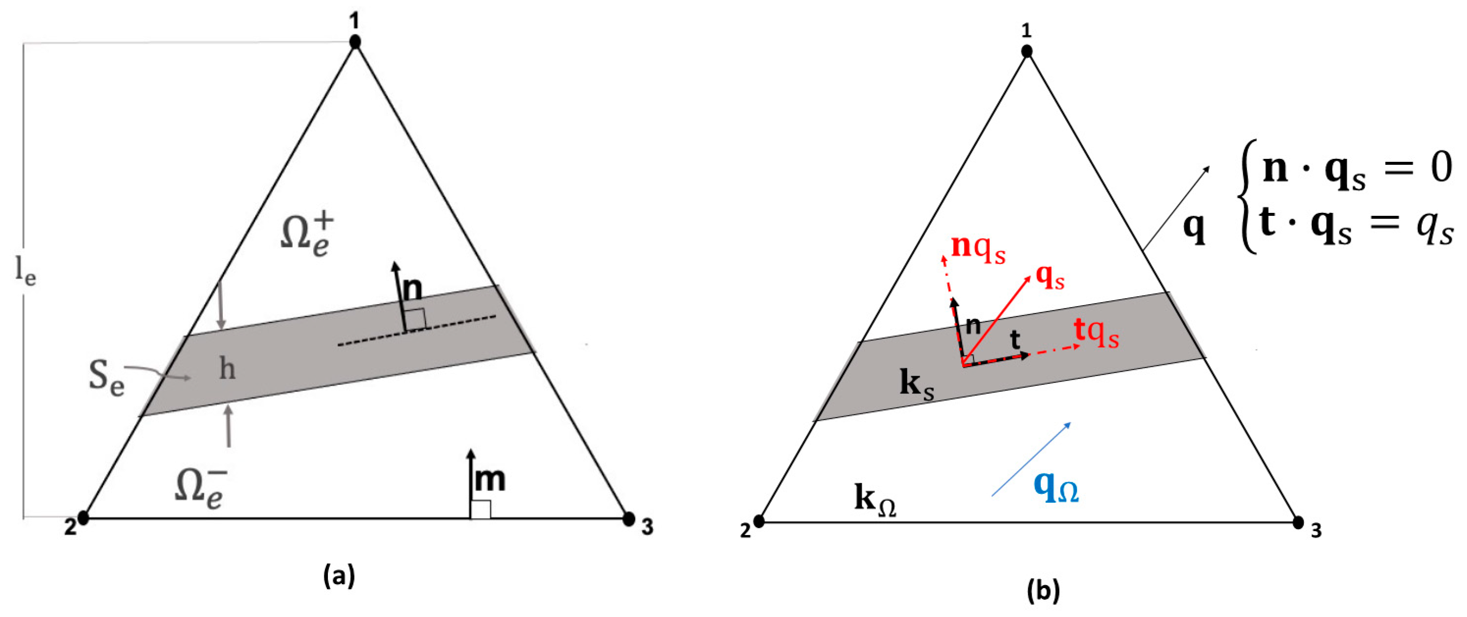
We used the mathematical development of the continuous approximation of embedded discontinuities proposed by Beserra et al. [35], which was also applied by Silva et al. [18]. This approach was implemented in the CODEBRIGHT in-house software [57,58], a finite element-based code to perform numerical analysis of fluid flow in deformable porous media in a fully coupled scheme. The embedding process, which considers the triangular element with three nodes from the domain (length, band, and width), is divided into two parts, isolating node 1 from nodes 2 and 3, as shown in Figure 2a. Darcy’s flow into the discontinuity is decomposed in a tangential and normal component as is shown in Figure 2b.
The formulation adopted in the present work considers that the fluid flow in a fracture occurs in its direction. Therefore, we considered only the tangential component. Darcy’s law can be written for continuum (qΩ) as follows:
q Ω = K Ω p ,
where KΩ is the permeability tensor of the continuous part, and Darcy’s law for fracture (qs) is
q s = K s p ,
where Ks = ks/μ.
The finite elements approach considers that the flow at the fracture will occur over the entire element thickness. As presented by Silva et al. [18], to ensure that the element transmissivity in the fracture direction is the same as the transmissivity of the embedded fracture, the fracture permeability Ks is multiplied by the ratio h/le. The resulting Equation is:
q s = h l e K s t t p ,
where t is the discontinuity direction, h is the thickness of incorporated discontinuity, and le is the element size.
Because a fracture in a porous medium represents a preferred path for flow toward discontinuity, it induces anisotropy in the direction of the fracture throughout the medium. As a result, an effective permeability tensor for the element is given by:
q = K ef p
K ef = ( K Ω + h l e K s t t )
Two different permeability variation laws are adopted, one for the continuum portion and the other for the fracture. Estimation of intrinsic fracture permeability ks can be performed through models that consider fractures with rough walls or filled with proppant material. We used the law of parallel plates in the models built for this research [35,59].
k s = k o ( h h o ) 2
where ko is the permeability in the continuum portion, h is the fracture thickness, and ho the initial fracture aperture.
For the rock matrix, we adopted the isotropic permeability law, described as follows:
k = k o ( ϕ ϕ o ) A
where ϕo is the initial porosity, ϕ is the porosity calculated after perturbations induced by rock deformation, and A is a parameter to be determined experimentally [36,60].
The continuity equation that governs the fluid flow in the porous media, considering a rigid medium and without gravitational effect, is given by:
ϕ ρ f t + · [ ρ f q ] = 0
where ϕ is the host rock porosity and q is the fluid flux vector given by Equation (8).
The fluid density is related to pore pressure according to the following expression:
ρ f = ρ f 0 e β ( p p 0 )
where ρf0 is the reference density, β is the fluid compressibility, p is the pressure, and p0 is the reference pore pressure.

2.3. Calculation of Shape Factor for Dual-Porosity—Permeability Models

The finite element method with embedded discontinuities allowed monitoring the fracture flow rate by applying the fluid flow Equation in the rock matrix to derive the shape factor that best corresponds to the simulation results.
Assuming that the matrix is a homogeneous and isotropic medium, ϕm represents the porosity, βm the compressibility, km the permeability tensor, and μ the viscosity, a general expression of the Equation for matrix pressure, pm(x,t), is given by:
{ ϕ m β m p m ( x , t ) t + · q m = 0                   e m             Ω × ( 0 , T ) q m = k m μ p m ( x , t ) p m ( x , t ) = p f                     for        Γ m f × ( 0 , T ) q m · n = 0            for     Γ N × ( 0 , T ) p m ( x , t ) = p m , 0         in      Ω × ( t = 0 )
Considering the domain border Ω given by Ω = Γ m f Γ N where Γmf represents the matrix-fracture interface, ΓN is the boundary on which the null flow is imposed, and n is the normal vector of ΓN outside the domain Ω, pf is the fracture pressure, and pm,0 is the initial matrix pressure.
Zimmerman et al. [59] developed two equivalent expressions to calculate the shape factor, one based on the mean matrix pressure and the other with flow defined by Ω . Thus, the following expression is adopted to introduce the shape factor α(t):
p m ( x , t ) · n p m ¯ ( t ) p f δ t
where p m ¯ ( t ) is the measure of pm(x,t) on domain Ω:
p m ¯ ( t ) = 1 | Ω | Ω p m ( x , t ) d Ω
The parameter δ t in Equation (15) measures the penetration depth of perturbation into pm(x,t) caused by pf. Thus, the expression to calculate the shape factor is given by:
α ( t ) = | Γ m f | | Ω | δ t
where |Γmf| denotes the area Γmf, and α(t) is the transient shape factor.
We have adopted an expression to obtain the shape factor as a function of mean pressure p m ¯ , using the Gauss theorem and the balanced Equation (4), described as follows:
α ( t ) = ϕ m β m μ k m ( p m ¯ ( t ) p f ) p m ¯ ( t ) t
In the limit t → ∞, the stationary value of such a parameter is obtained.
α = l i m t   α ( t )
As α is a geometric parameter, it does not depend on pf or the hydrodynamic properties of the matrix.

2.4. Oda Tensor Approach for Equivalent Permeability Estimation

Oda [45] proposed an analytical method to compute equivalent fracture permeability, which is widely used in DFN upscaling due to its efficiency [61,62]. For a grid cell with known fracture areas, Ak, and transmissivities, Tk, obtained from the DFN model, an empirical tensor that considers only fracture geometry can be calculated as follows:
F = 1 V k = 1 N f k A k T k n n
where F is the fracture tensor, V is the grid cell volume, N is the total number of fractures in a grid cell, fk is the hydraulic connectivity for fracture k (generally assumed to equal to 1), Ak is the area of fracture k, Tk is the transmissivity of fracture k, and n is the components of a unitary normal to the fracture.
Oda’s permeability tensor is derived from F by assuming that F expresses fracture flow as a vector along the fracture’s unit normal. Assuming that fractures are impermeable in a parallel direction to their unit normal F must be rotated into planes of permeability [63].
k = 1 12 ( tr   F   I F )
where k is the permeability tensor, F is the fracture tensor, I is the identity matrix, and tr F is the sum of the main diagonal of the fracture tensor. According to Elfeel [64], a limitation to the application of Equation (21) is that fractures of any length will contribute to the permeability value, including if fractures do not allow percolation in a cell.

3. Modeling of Studied Cases

The characteristics of models, four synthetic cases, and three real scenarios of a Brazilian pre-salt reservoir, used to perform the proposed methodology are described below.

3.1. Artificial Fractured Media

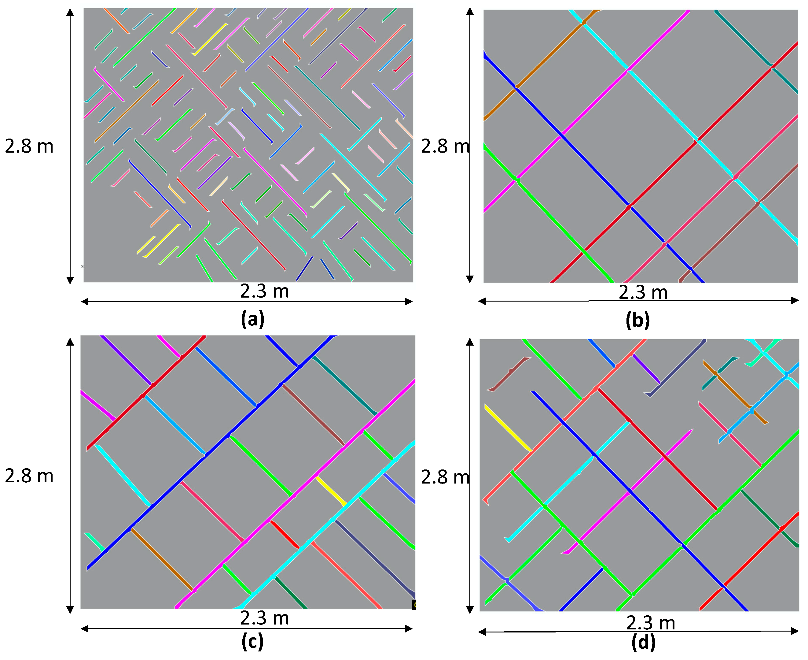
The synthetic 2D sections analyzed in this work were created based on scenarios presented and tested by Silva et al. [18]. We have adopted changes in their models regarding the dimensions and fracture characteristics as the apertures. The scenarios consider four different topological patterns with different intensities and distribution of fractures that allowed the analyses of the impact of the topology on the shape factor and validating the results they present for the equivalent permeability (Figure 3).
The quantification of topological fracture node types for each scenario (Figure 3) is presented in Table 1.
For all cases, the fracture intensity was calculated according to the method proposed by Dershowitz and Einstein [24], which defines measures of fracture abundance by Pxy, where x is the dimension of the sampling region and y the dimension of the measured feature (e.g., Sanderson and Nixon [42]).
We used the P22 sampling technique (area of fractures per sampling area) to calculate the relationship between the topology of the fractures and the equivalent permeability. The dimensionless intensity calculated from the P22 analysis is given by P 22 = N L L C 2 / A = P 21 · L c , and it has dimensions [L−0] where Lc is the characteristic length and is defined as the arithmetic mean of the line lengths. We used a MATLAB® script to build the FEM (parameterized meshes). After loading the fracture coordinates (endpoints) and apertures, the script allows the extraction of the fracture permeability using the parallel plate theory (Equation (10)). We consider the matrix as isotropic and of low permeability, which simulates a tight reservoir scenario.
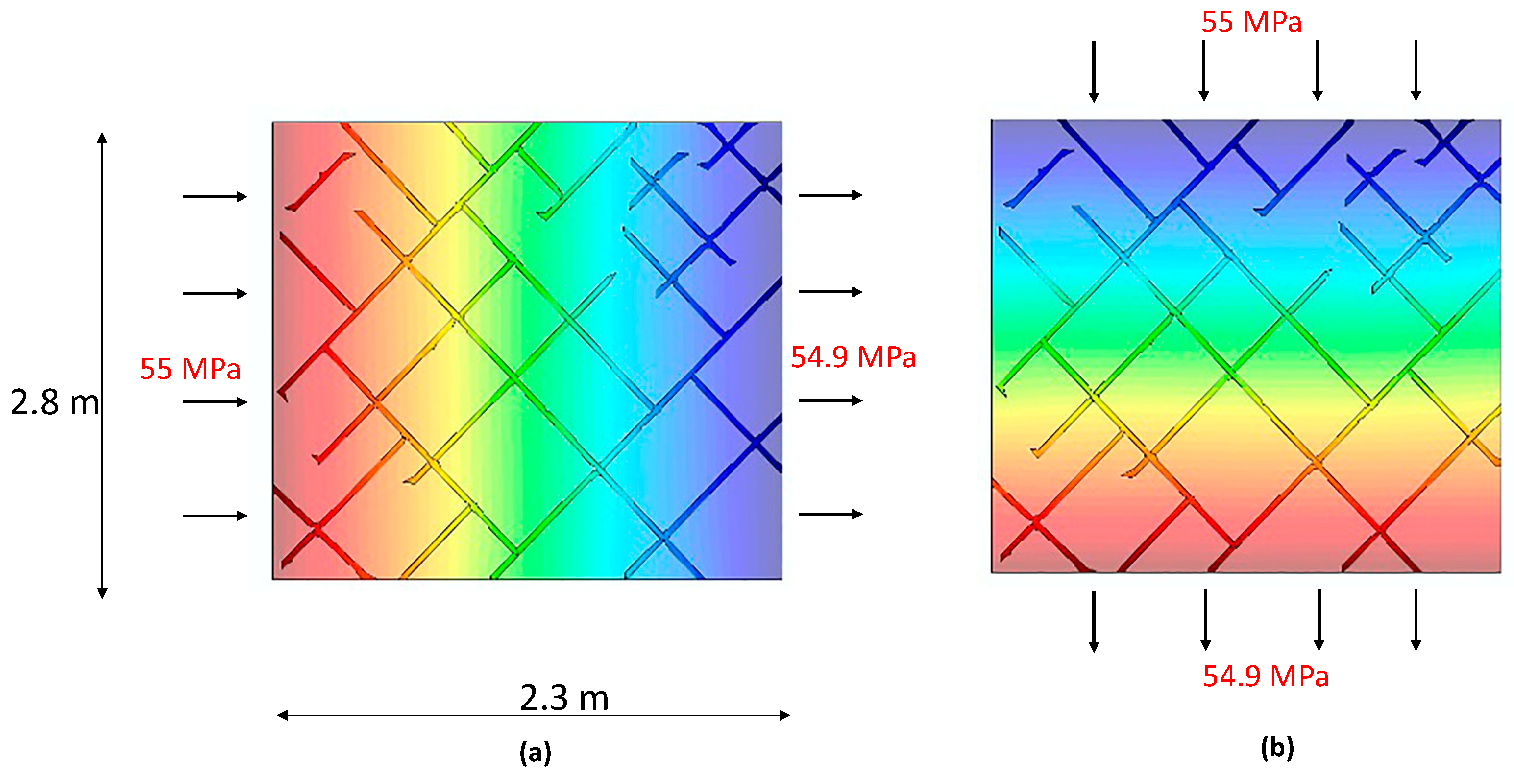
The simulation of hydraulic phenomena consisted of the injection of a single fluid-phase (water) on the left side of the models and fluid production on the right side of the domain. The fluid injection pressure was 55 Mpa, and the production pressure is 54.9 Mpa, leading to a pressure gradient of 0.1 MPa. The simulation was also conducted for all scenarios considering a vertical flow, using the same pressure values (Figure 4).
For the simulations, we considered a single-phase flow governed by a nonlinear form of Darcy’s law, the equivalent permeabilities computed from DFNs, and a flow-based upscaling approach.
Thus, the numerical simulation was conducted to obtain the shape factor. In the FEM used for simulations, the fractures were considered as flow lines. The shape factor was calculated numerically using the discrete fracture model for all flow states until reaching its pseudo-stationary value.

3.2. Real Fractured Reservoir Case: Brazilian Pre-Salt

The real case analyzed in our study is adapted from Falcão et al. [36]. They developed several DFN models for a carbonate reservoir from the Brazilian pre-salt interval (Figure 5). Figure 5 shows the model used to extract fracture distribution examples (bidimensional sections) used in this work. The Santos Basin pre-salt cluster is located in ultra-deep waters, 2000 m approximately, and 290 km offshore from the Rio de Janeiro coast. This cluster represents a prominent regional sequence covered by a continuous evaporitic sequence. The reservoirs are mainly composed of carbonate rocks, laminites, stromatolites, coquinas, and spherulites. Pre-salt development presents many challenges like water depths, reservoir heterogeneities, oil with the content of CO2 in the gas phase, and drilling challenges because of variable salt layer [65].
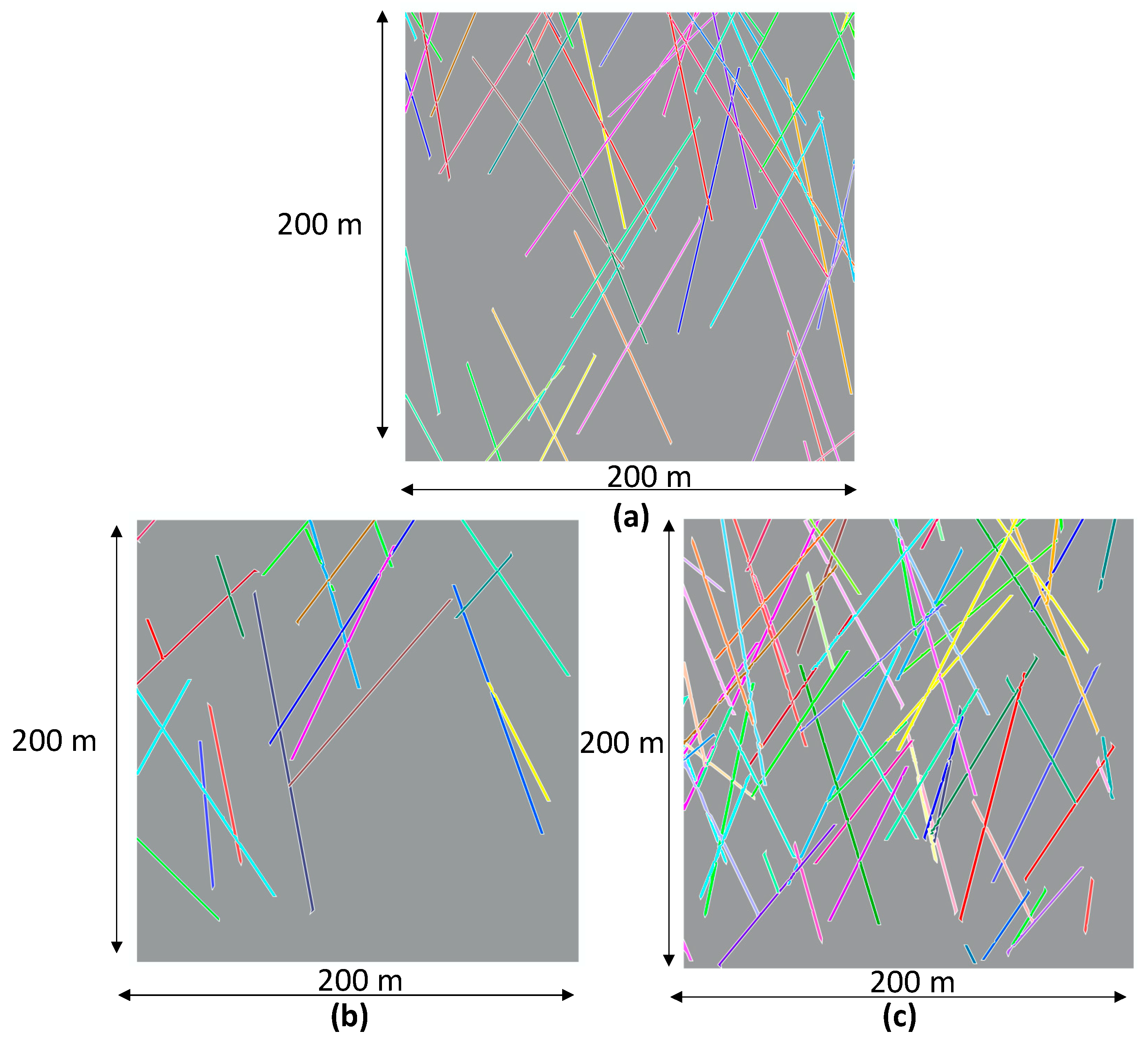
Figure 6 shows the three bidimensional scenarios, horizontal sections (slices), extracted from the tridimensional cell from the pre-salt reservoir model shown in Figure 5c. Each 2D section (200 × 200 m) presents a different fracture intensity and spatial arrangement. We have adopted the fracture parameters and coordinates used to compose the 2D sections after the original work of Falcão et al. [36]. The first 2D model, section 1, possesses 54 fracture planes (Figure 6a), the second, section 2, possesses 22 fractures (Figure 6b), and the third case, section 3, 75 fractures (Figure 6c). The building of the FEM created from the sections shown in Figure 6 followed the same procedures used to build the FEM from the artificial models shown in Figure 3 and Figure 5.
Table 2 shows topological pattern values of each section shown in Figure 6. These values are used in Equation (4) for the calculation of the hydraulic connectivity value f.

4. Results

4.1. Artificial Scenarios

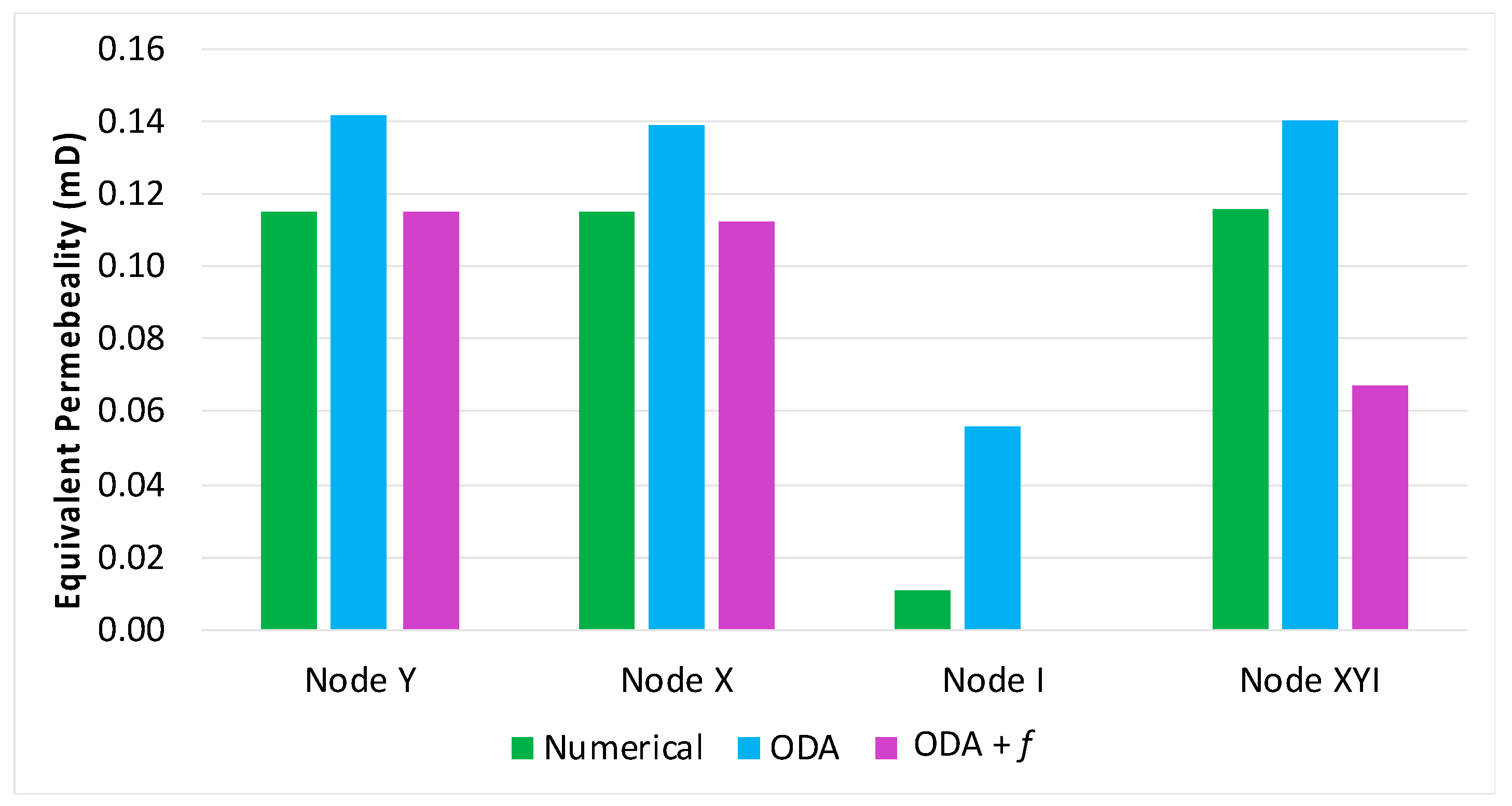
Figure 7 shows the results for the three artificial cases regarding the equivalent permeability calculated with the horizontal flow simulation (direction x). Oda’s method overestimates the equivalent permeability because it assumes that all the fracture planes cross the entire sample. Permeability calculated using the Oda method with the hydraulic connectivity f reached a better result, similar to the numerical simulation for the sections with Y- and X-nodes. The calculation of permeability with (f) for the I-nodes case resulted in negative values (not shown in the graph) because the values of nx and ny are zero, which resulted in inconsistent outputs, and the 0 value is assumed.
It indicates that Oda’s method cannot compute the equivalent permeability for the situation of topology dominated by I-nodes, which has no connection between fracture planes. The corrected Oda’s method presented reliable results for the cases dominated by X- and Y-nodes. The same aspect was demonstrated by Madden [66], that the geometric mean of heterogeneous bodies could be used to predict the physical properties of a homogenized matrix.
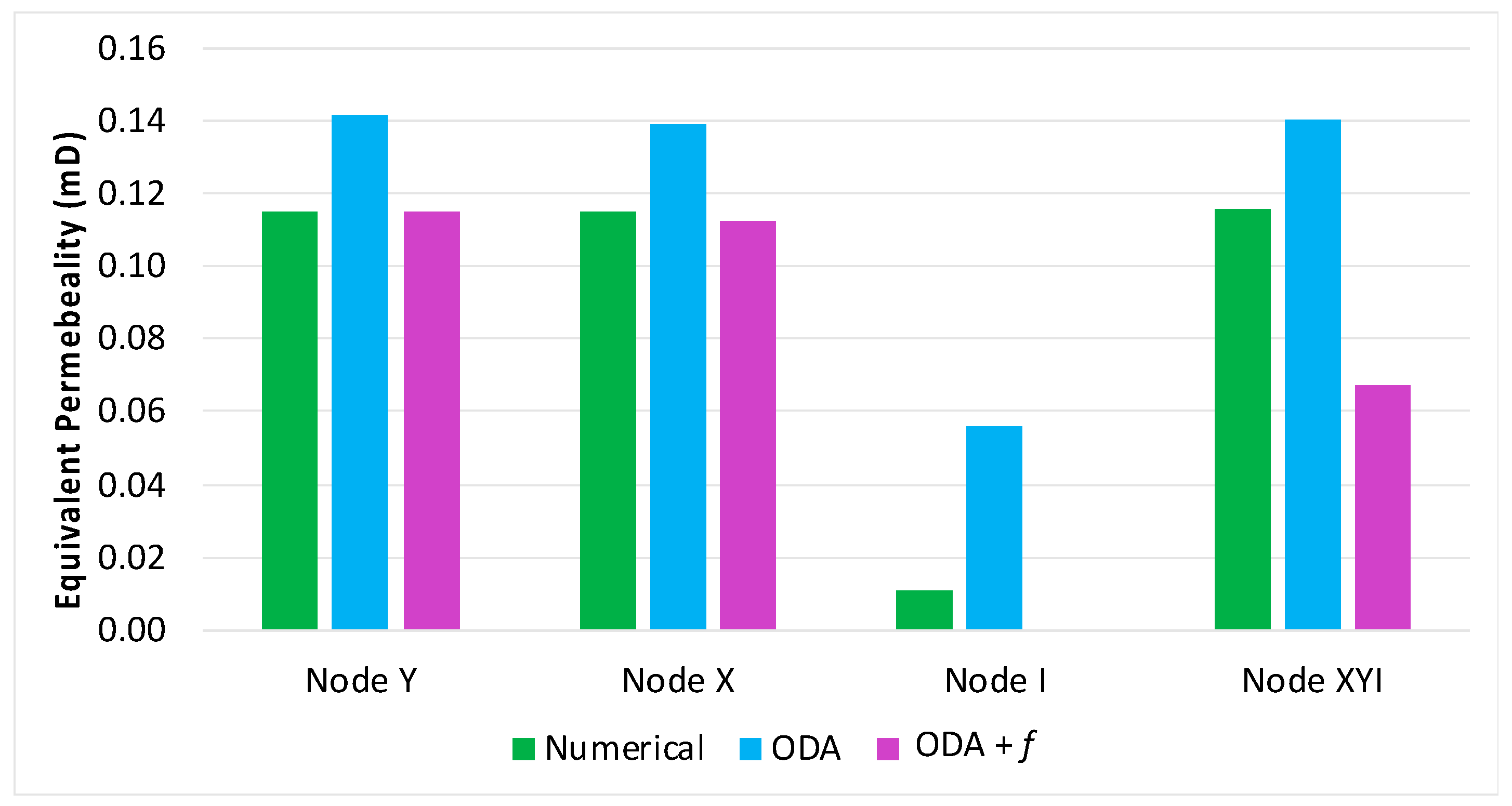
Figure 8 shows the results obtained for the equivalent permeability values obtained through the vertical flow simulation (y-direction). Results are close to those obtained for the horizontal flow (Figure 7) and agree with Silva et al. (2021). This similarity occurs because the arrangement does not affect the flow pattern in the two situations (Figure 7 and Figure 8).
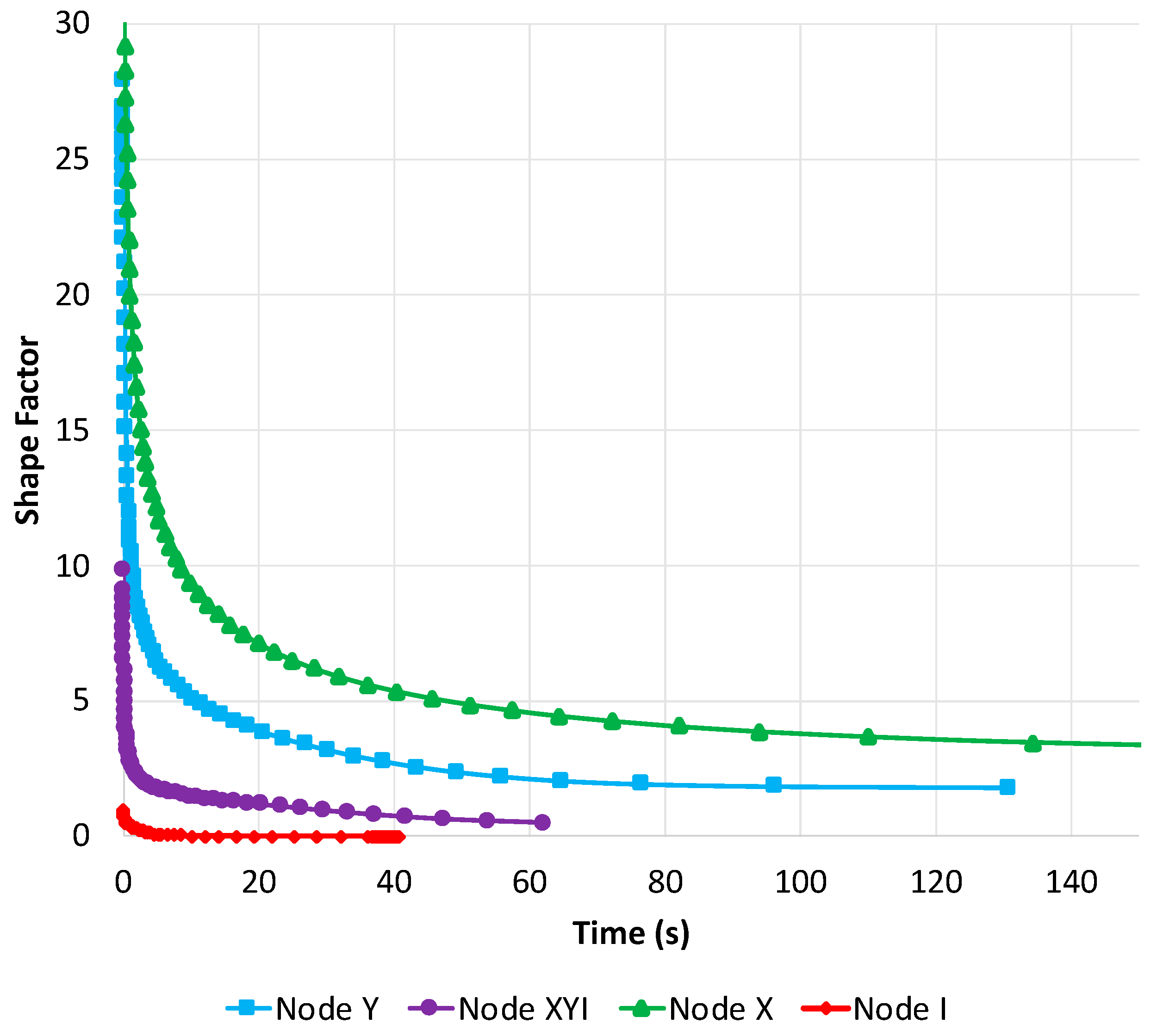
Figure 9 presents the shape factor behavior during the simulation for the synthetic scenarios. The significant impact of the I-node-dominant topology is shown, and the related curve reaches the pseudo-stationary state first, followed by the X-node and Y-node curves (Figure 9). This effect demonstrates that the lack of fracture connections dramatically affects the fluid transmissibility through the matrix.
The shape factor is defined when the curves flatten parallel to the X-axis. The building of synthetic cases has considered similar dimensionless fracture intensities based on the P22 distribution. This condition is important to assure that similar fracture areas with different element distributions would be compared.
Figure 10 presents the dimensionless fracture intensity P22 percentage defined for each synthetic case (Figure 10a) and the final shape factor value calculated for each case (after reaching the pseudo-stationary state) (Figure 10b). The case dominated by the X-node pattern shows the highest value of shape factor as expected because of the higher connectivity relationships. A similar response is observed for Y-node dominated topological patterns, while for combined (XYI) and dominated I-nodes scenarios, the values are low. It leads to the evidence that the fracture crossing predominance induces a more considerable matrix-fracture transfer and can impact the fluid flow for the dual-porosity dual permeability media.
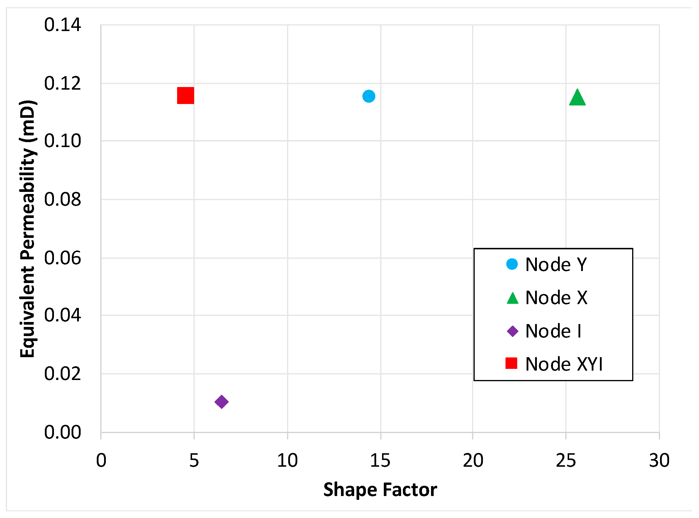
Figure 11 shows the result of a cross-correlation between the computed equivalent permeability and shape factor for each case. The patterns dominated by X-nodes and Y-nodes show slightly higher equivalent permeability, which demonstrates the negative impact caused by I-nodes in the X-Y-I pattern (Figure 11), and that the shape factor, regardless of the fracture intensity, affects the permeability anisotropy [67].
Table 3 shows the properties of the synthetic cases and results obtained through the simulation: the equivalent permeability, factor f, and the shape factor. It demonstrated that the lower shape factor values resulted from the influence of the I-node terminations.

4.2. Numerical Simulation of Real Fractured Reservoir Scenarios of Brazilian Pre-Salt Interval

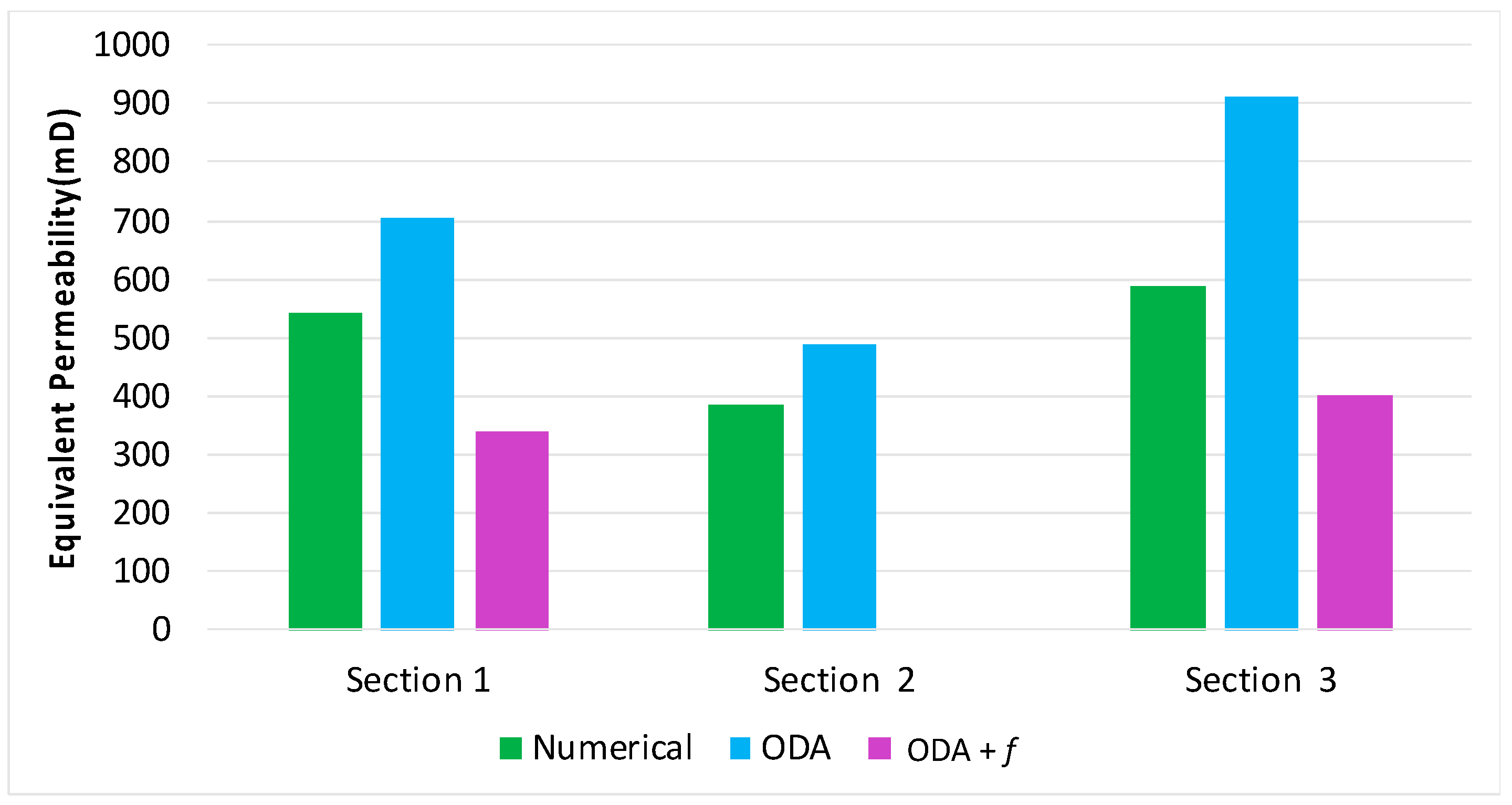
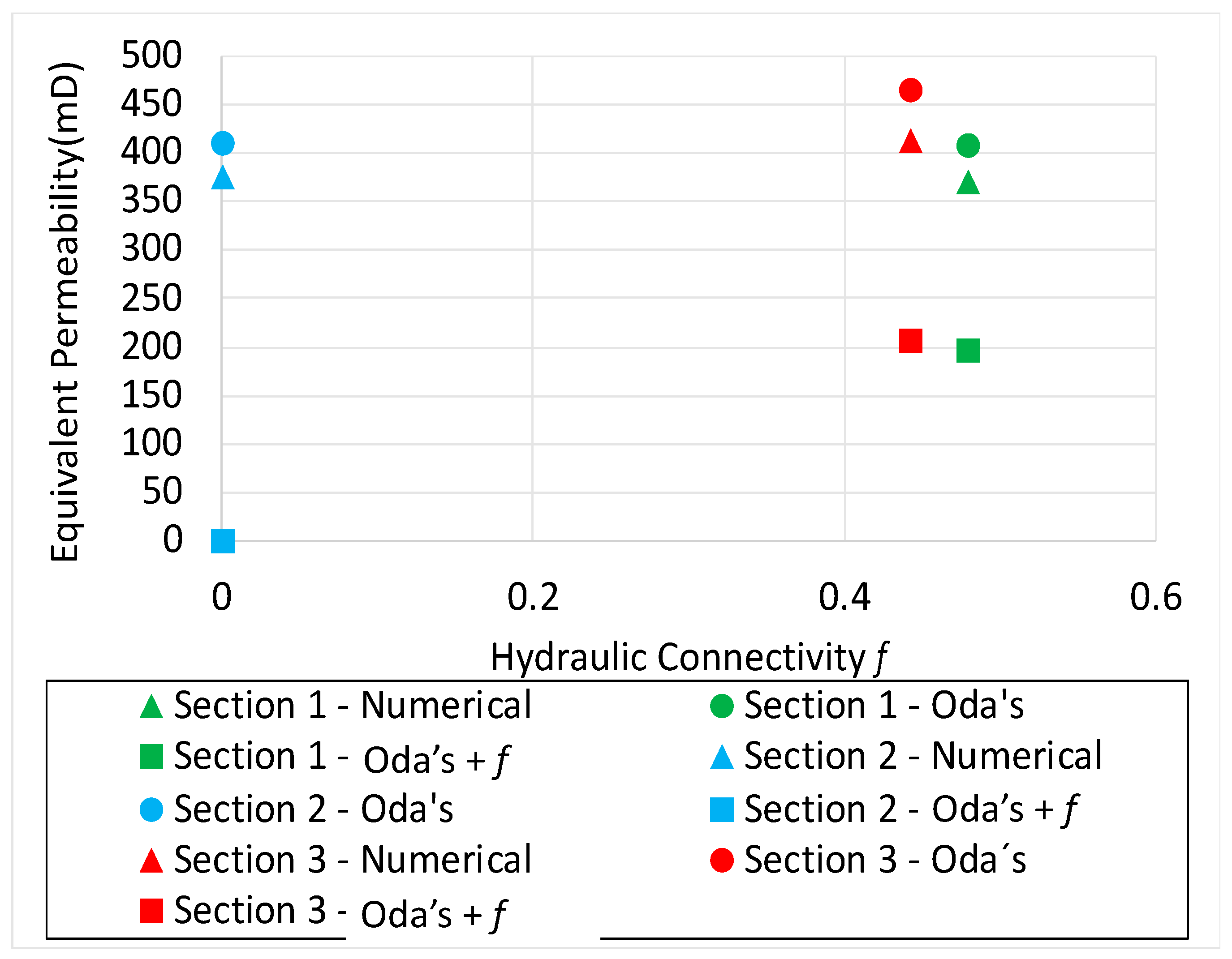
Figure 12 and Figure 13 show the results of equivalent permeability computed through Oda’s method, and Oda’s method corrected with hydraulic connectivity and numerical simulation for horizontal and vertical flow for the three real cases (Figure 6). For the horizontal flow situation, Oda’s method yielded higher values of equivalent permeability, and it overestimated the numerical simulation results, which showed slightly lower values (Figure 12). Application of the Oda method corrected with the hydraulic connectivity f resulted in the lowest values for the equivalent permeability, compared to the numerical simulation. This effect results from the influence of I-node fractures, and the opposite is observed for Oda’s analytical solution (Figure 12). De Dreuzy [68] demonstrated a significant coupling between flow heterogeneities at the fracture scale and flow heterogeneities at the network scale that cannot be solved through the hydraulic connectivity approach, as observed in real cases presented here. For section 2, the value of hydraulic connectivity f was 0 due to the high number of I-node fractures compared to the X- and Y-node types (Figure 6b). Thus, Equation (4) becomes negative, which implies a lack of coherency.
Figure 13 presents the results for the calculation of permeability regarding the vertical flow scenario. The results showed higher values, in certain cases, more than the double extracted with each method, compared to the horizontal flow scenario (Figure 12). It occurs because the fracture planes are aligned with the flow direction. Values computed for sections 1 and 3 show a significant difference between the numerical and analytical results obtained with Oda’s model. As observed with the synthetic cases, this effect occurs because this method assumes that the fracture planes cross the entire model area. After the application of the correction factor to the topological aspect, the result becomes close to the numerical solution. Again, this result shows the influence of the I-node fractures in the transmissibility phenomena.
Figure 14 and Figure 15 show the cross-correlation of the computed equivalent permeability and the hydraulic connectivity f calculated with the topological analysis for the horizontal and vertical flow scenarios, respectively, for the three real cases treated. For the horizontal flow scenario, results obtained with Oda’s method are the closest to the result reached with numerical simulation. For this specific scenario, the hydraulic connectivity does not help to achieve a reliable solution. However, the value of hydraulic connectivity f is efficient to demonstrate the impact of the topological I-nodes in the three real cases analyzed.
For the vertical flow scenario, sections 1 and 3 show a similar correlation for the factors analyzed, and section 2 presents a remarkable difference relate to the connectivity effect (Figure 15). As observed for the horizontal flow scenario, the hydraulic connectivity f has a similar pattern because it does not depend on the direction of the flow in the fractured medium.
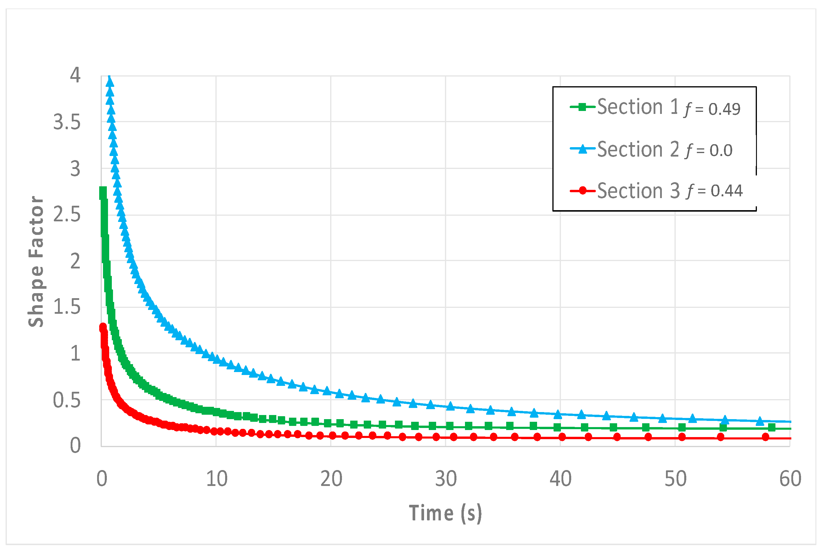
Figure 16 shows the shape factor calculated as a function of time for the three real 2D sections. The curves show the influence of fracture density on fluid transfer between the fracture network and the matrix. For section 2, which has only 23 fractures, it takes longer to reach a pseudo-stationary state. As observed above, the lack of coherence for the connectivity factor for section 2 prevents a better comparison of correlation with other parameters.
Figure 17 presents a cross-correlation, a comparison between the dimensionless fracture intensity P22 (the relationship between the area of fractures over the area of the section) Figure 17a, and the shape factor related to the topology patterns of fracture networks for the three 2D sections derived from the pre-salt reservoir model Figure 17b. The section 3 presents the higher fracture intensity and the lower shape factor (Figure 17). The section 2, dominated by I-node endings, shows the higher shape factor and the lower fracture intensity.
Figure 18 shows cross-correlation between the shape factor value at its stationary state and the calculated hydraulic connectivity f for each 2D section. Section 3 presents lower values for these two parameters, due to the influence of I-node fracture endings. However, section 3 presents the highest fracture intensity, as shown in Figure 17. Section 2 presents zero value for the shape factor due to the lack of connectivity caused by the dominance of I-node fractures, and the lack of coherence prevented correlation. Section 1 presents a higher connectivity shape value and, relatively, the higher shape factor of the three sections.
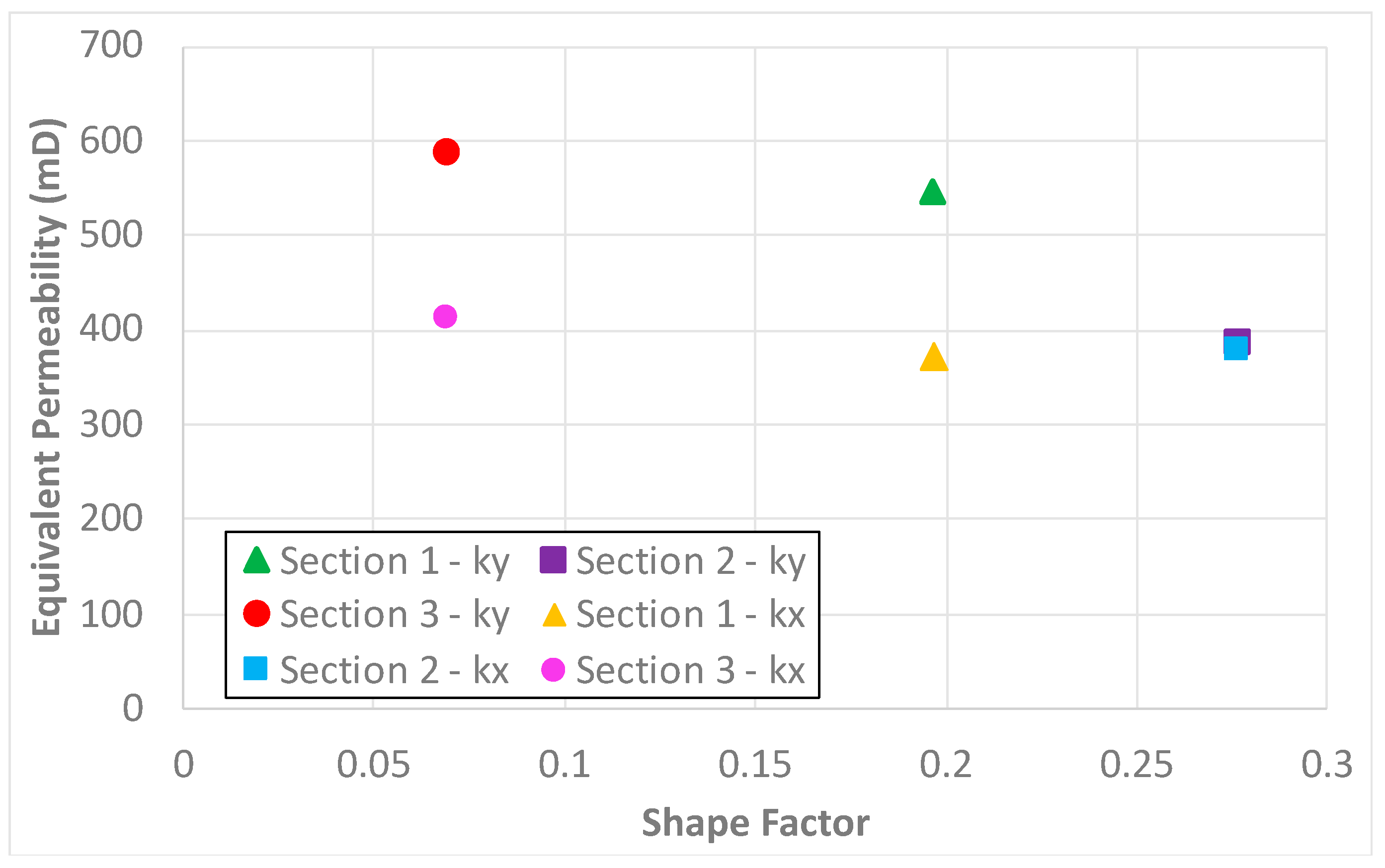
Figure 19 shows the correlation between computed equivalent permeability and the shape factor calculated from the topological scenarios with X- and Y-node types. Section 3 presents a lower shape factor but higher equivalent permeability. Section 2 shows markedly higher values of shape factor but slightly lower equivalent permeability values than section 3. Section 2 also presents the highest shape factor but relatively lower equivalent permeability to sections 1 and 3.
Table 4 shows the properties of the three 2D sections extracted from the pre-salt reservoir model and results obtained through the simulation: the equivalent permeability, factor f, and the shape factor. This integration highlights the relationship between the topological patterns and the resulting equivalent permeability. It also points to the importance of defining both the number of connections between fracture planes and the number of I-node types present in the DFN because it controls the permeability effect and the interaction of fluid between fractures and rock matrix.
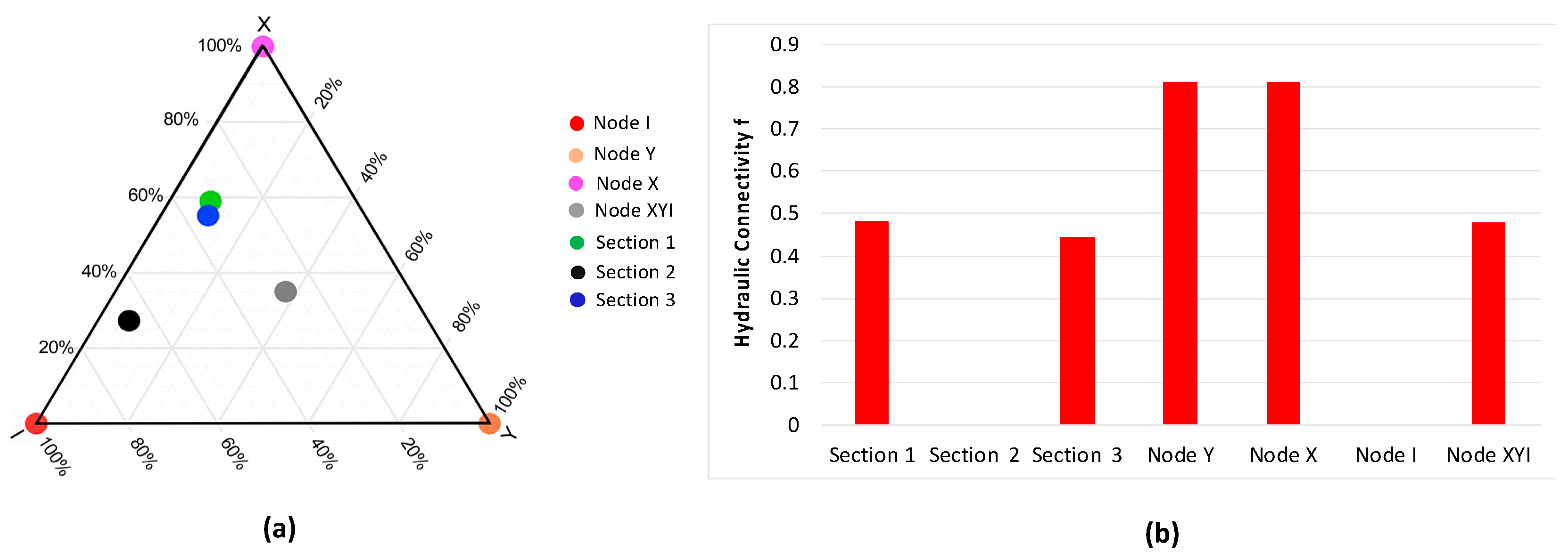
We present a ternary diagram in Figure 20a that shows the percentage of each topology pattern for the three sections studied. Figure 20b shows a bar chart with the value for the hydraulic connectivity factor for the same sections. The hydraulic connectivity f tends to be higher in the sections with a higher percentage of X- and Y-nodes. However, it does not indicate higher equivalent permeability fields, and the definition of topological aspects may be essential to constraining hydraulic simulations in fractured media.
The results showed the main effects of topology variations in upscaled permeability tensor estimation and shape factor, considering a low and fixed matrix permeability (e.g., tight reservoir). This work provided an analysis of fracture patterns influence (type and degree of connections) in the cell scale used in reservoir simulation.

5. Discussion

There are many advancements since the early works on the numerical modeling of geological scenarios. Jing and Stephansson [44] showed that applying a mathematical formulation to represent fractured rocks cannot be arbitrary, and it must relate to the topological properties of the fracture network. Haddad et al. [69] showed that the heterogeneity of fractured reservoirs profoundly affects the rate of mass transfer between the fracture system and matrix blocks. One of the heterogeneity sources is related to the variable fracture intensity.
In this study, we successfully used embedded discontinuities in FEM-based models, regarding real and artificial scenarios, of fractured porous media to execute flow simulations. A similar approach was also successfully used for real cases in Brazilian pre-salt reservoirs by Falcão et al. [36].
Performing numerical simulation with the incorporated discontinuities has demonstrated reliability for fluid flow simulation in fractured media, including coupled simulations [70,71,72,73,74,75,76]. This method presents an alternative to the classical techniques based on the use of interface elements. It also represents an alternative for analysis that requires the repeated rewiring of the geometry, as observed in discrete fracture methods in which fractures are represented explicitly in the model [77,78]. The approach allows representing fractures with lines and surfaces [79]. This technique also presents the advantage of reducing the computational costs and simplifies the discretization process of fractured media [35] and directly includes the fracture contribution into the matrix without any spatial portioning.
The artificial and real case models treated here were built with the FEM method, and the flow simulations performed allow calculating the equivalent permeability and the shape factor for all the scenarios. The 2D real scenarios were built from a cell extracted from a larger DFN model of a reservoir from the Brazilian pre-salt interval [36]. Three horizontal slices were acquired from a 3D cell and provided three bidimensional sections with proper fracture sets. The simulations allowed us to evaluate the impact of fracture topology and highlight aspects of the computation of equivalent permeability and shape factor in the fractured medium. Fracture topology handles the generalization of spatial relationships as the connectivity and continuity of fracture planes. It refers to properties that are unchanged by the continuous transformation of the space in which the fractures are embedded, the deformation (strain) of the geometrical properties (lengths and angles), a concept familiar in many areas of geology [18,42]. Topological analysis of NFRs is fundamental to predict the hydraulic connectivity f, which involves the fracture network and the rock matrix in classical dual-porosity problems. Besides the numerical simulation, we used Oda’s analytical method, and the correction applied to this method according to Sævik and Nixon [41]. The correction considers the fracture system connectivity and fractures characteristics using the quantification of topological fracture node types. Although these authors do not compare results with Oda’s original method, several authors have made advances in this analytical method and shown the need to consider other representative parameters to represent the permeability tensor of fractured media more realistically [78,80,81]. Fumagalli et al. [78] implemented the embedded discrete fractures technique and compared the simulations with Oda’s method used in a commercial simulator. Their results showed the accuracy of the embedded fracture models compared to the analytical method.
Considering the correction to Oda’s method provided by the topological analysis, the hydraulic connectivity f is used to represent a new parameter in the general equation of Oda’s tensor. Results obtained through simulation for the synthetic cases with X- and Y-nodes were similar to the values obtained with the corrected Oda method. This outcome demonstrates the importance of analyzing the hydraulic connectivity f to estimate equivalent permeability [43,82].
Silva et al. [18] presented a numerical tool for fracture modeling, which was tested in synthetic bidimensional models of fractured media. They analyzed the capacity of FEM models with embedded discontinuities to calculate upscaled equivalent permeability and the influence of topological patterns in the flow. These authors analyzed the influence of topological patterns in the equivalent permeability. They concluded that the fracture intensity, connectivity, and topology pattern play an important role in the upscaled permeability. These authors demonstrated the reduced equivalent permeability of fracture networks dominated by I-nodes, due to the lack of connectivity, compared to networks with X- and Y-node patterns, as was also found by the present study.
Lahiri [83] performed the calculation of the effective permeability of a fracture network and used topological connectivity through analytical expressions, considering fractal and multifractal distributions. The author concluded that the permeability of fracture systems increases rapidly with the growth in length of the branch segments. Longer branch segments in fracture networks play a critical role in determining the permeability of the fractured reservoir. We found similar results in the calculation of equivalent permeability through topology analysis of the real cases. Larger branches of fracture systems tend to have more connectivity with other fracture planes, but I-node fractures tend to form short planes.
The shape factor was first introduced by Barenblatt et al. [84]. In this approach, the matrix and the fractures are divided into two continuum systems: The fractures are considered the main global flow paths (fractures have high permeability and low storage capacity), while the rock matrix is the main fluid storage sink (the matrix blocks present high storage and low permeability). The two systems are connected, and they interact either directly or indirectly with the global connection neighboring fractures. The concept of double porosity was extended and applied to reservoir engineering by Warren and Root [46], mainly for pressure test analysis. They developed a method based on the general premise that fractures are evenly spaced and allow for variations in fracture width to satisfy real anisotropy conditions in a naturally fractured reservoir. The fracture-matrix transfer term, governed by shape factor, cannot be represented by pseudo-steady-state. Rather, it involves transient periods of variable magnitude depending on the considered flow case. Furthermore, the shape factor is not just a value. The deficient concept of the pseudo-state transfer assumption explains why a certain controversy developed around the definition of the shape factor [85]. The fracture-matrix transfer problem involves a time convolution between fracture flow conditions. The actual flow occurs within the matrix medium.
Certain works have developed transient methodologies to obtain the shape factor, regarding the time effect, and a real representation of the fracture matrix interaction regarding the production or injection processes in the reservoir [23,47,51,52,53,86,87,88,89,90]. Rostami [91] demonstrated that the shape factor is a function of time, and its value could be different for regular and irregular shapes.
The analysis performed in this study considered a novel approach to obtain the shape factor as a function of time and compared the equivalent permeability computed through numerical simulation with analytical methods corrected with topological analysis in bidimensional artificial and real scenarios. The most relevant result demonstrated the influence of the I-node topology feature on the flow in fractured media. Fracture networks dominated by I-node types hinder the transfer effect between the fractures and the rock matrix, and the impact in the equivalent permeability can be relevant, despite the fracture density. Thus, the arrangement of fractures that influences the topological nodes and the hydraulic connectivity can provide a simplified and fastened estimate of fluid control parameters (permeability and shape factor) for numerical simulations of fractured reservoirs.

6. Conclusions

Numerical simulations were successfully performed to obtain the effective permeability regarding artificial and real cases with dual-porosity in fractured media built with FEM models. The results were compared with data obtained through analytical methods, corrected with topological analysis of fracture systems (I-nodes, Y-nodes, and X-nodes).
Results showed the impact of connection between the fractures and the behavior of properties directly related to flow, such as permeability. The analysis demonstrated the relationship between the fracture topology and shape factor. Fractured media dominated by I-node terminations result in smaller shape factors than systems composed by other fracture node types. This finding is directly related to the lack of connectivity.
Simulations performed on the scenarios showed that in fractured systems with fewer X- and Y-nodes than I-nodes, the equation used to define the fracture connectivity f will return negative results. This finding prevented the further extraction of properties such as equivalent permeability or the shape factor regarding the hydraulic conductivity f of the medium.
The results presented demonstrated the direct relationship of the shape factor with the geometry of the fractures and the fracture intensity aspect and evidenced the impact of these variables on the shape factor.
The comparative analysis demonstrated that the analytical methods are satisfactory to estimate equivalent permeability of idealized fractured systems. These represent artificial cases in terms of the fracture density and the connectivity factor. However, the test with real scenarios, a DFN from a pre-salt reservoir, demonstrated that the analytical methods are not efficient to estimate the equivalent permeability of the fractured medium, including with the corrected analytical method by using topological analysis.
The study reinforces the contribution of the fracture topology theory in obtaining input parameters for double porosity and double permeability models such as permeability and shape factor.
As a recommendation for the work evolution, one can consider the variable aperture and cement filling due to diagenetic effects in fractures, which is crucial to reproduce realistic models. The adoption of a coupled hydro-mechanical approach should be considered in further developments to establish the effect of fractured media (matrix rock and fractures) and stress-strain in the upscaled process need to be analyzed.

Author Contributions

Conceptualization, I.F.G., L.J.d.N.G., T.S.d.M. and L.L.A.; methodology, I.F.G., L.J.d.N.G., L.B., B.M., L.C.P., T.S.d.M., J.A.B. and L.L.A.; software, L.J.d.N.G., L.B., B.M. and L.L.A.; formal analysis, I.F.G., J.A.B., L.L.A. and T.S.d.M.; investigation, L.L.A., I.F.G., J.A.B., T.S.d.M., L.J.d.N.G. and B.M.; writing—original draft preparation, L.L.A., I.F.G., L.J.d.N.G., J.A.B. and T.S.d.M.; writing—review and editing, L.L.A., J.A.B. and I.F.G.; supervision, I.F.G., L.J.d.N.G. and J.A.B. All authors have read and agreed to the published version of the manuscript.

Funding

This research received no external funding.

Institutional Review Board Statement

Not applicable.

Informed Consent Statement

Not applicable.

Acknowledgments

The authors thank the financial support provided by Petrobras, Energi Simulation, and CNPq-Brazil.

Conflicts of Interest

The authors declare no conflict of interest.

References

  1. Jaffré, J.; Mnejja, M.; Roberts, J. A discrete fracture model for two-phase flow with matrix-fracture interaction. Procedia Comput. Sci. 2011, 4, 967–973. [Google Scholar] [CrossRef]
  2. Lima, B.E.M.; De Ros, L.F. Deposition, diagenetic and hydrothermal processes in the Aptian Pre-Salt lacustrine carbonate reservoirs of the northern Campos Basin, offshore Brazil. Sediment. Geol. 2019, 383, 55–81. [Google Scholar] [CrossRef]
  3. Lima, B.E.M.; Tedeschi, L.R.; Pestilho, A.L.S.; Santos, R.V.; Vazquez, J.C.; Guzzo, J.V.P.; De Ros, L.F. Deep-Burial Hydrothermal Alteration of the Pre-Salt Carbonate Reservoirs from Northern Campos Basin, Offshore Brazil: Evidence from Petrography, Fluid Inclu-sions, Sr, C and O Isotopes. Mar. Pet. Geol. 2020, 113, 104143. [Google Scholar] [CrossRef]
  4. Philip, Z.G.; Jennings, J.W.; Olson, J.E.; Laubach, S.E.; Holder, J. Modeling Coupled Frac-ture-Matrix Fluid Flow in Geomechanically Simulated Fracture Networks. SPE Reserv. Eval. Eng. 2005, 8, 300–308. [Google Scholar] [CrossRef]
  5. Bratton, T.; Canh, D.V.; Van Que, N.; Duc, N.V.; Gillespie, P.; Hunt, D.; Li, B.; Marcinew, R.; Ray, S.; Montaron, B.; et al. The Nature of Naturally Fractured Reservoirs. Oilfield Rev. 2006, 18, 4–23. [Google Scholar]
  6. Laubach, S.E.; Olson, J.E.; Gross, M.R. Mechanical and fracture stratigraphy. AAPG Bull. 2009, 93, 1413–1426. [Google Scholar] [CrossRef]
  7. Olson, J.E.; Laubach, S.E.; Lander, R.H. Natural fracture characterization in tight gas sandstones: Integrating mechanics and diagenesis. AAPG Bull. 2009, 93, 1535–1549. [Google Scholar] [CrossRef]
  8. Mohammed, I.; Olayiwola, T.O.; Alkathim, M.; Awotunde, A.A.; Alafnan, S.F. A review of pressure transient analysis in reservoirs with natural fractures, vugs and/or caves. Pet. Sci. 2021, 18, 154–172. [Google Scholar] [CrossRef]
  9. Bonnet, E.; Bour, O.; Odling, N.E.; Davy, P.; Main, I.; Cowie, P.; Berkowitz, B. Scaling of Fracture Systems in Geo-logical Media. Rev. Geophys. 2001, 39, 347–383. [Google Scholar] [CrossRef] [Green Version]
  10. Laubach, S.E.; Gale, J.F.W. Obtaining Fracture Information for Low-Permeability (Tight) Gas Sandstones from Sidewall Cores. J. Pet. Geol. 2006, 29, 147–158. [Google Scholar] [CrossRef]
  11. Laubach, S.E.; Lander, R.H.; Criscenti, L.J.; Anovitz, L.M.; Urai, J.L.; Pollyea, R.M.; Hooker, J.N.; Narr, W.; Evans, M.A.; Kerisit, S.N. The Role of Chemistry in Fracture Pattern Development and Opportunities to Advance Interpretations of Geological Materials. Rev. Geophys. 2019, 57, 1065–1111. [Google Scholar] [CrossRef] [Green Version]
  12. Nelson, R.A. Geologic Analysis of Naturally Fractured Reservoirs, 2nd ed.; Gulf Professional Publishing: Boston, MA, USA, 2001. [Google Scholar]
  13. Laubach, S.E. Fracture Networks in Selected Cretaceous Sandstones of the Green River and San Juan Basins: Wyoming, New Mexico, and Colorado. In Geological Studies Relevant to Horizontal Drilling: Examples from Western North America; Schmoker, J.W., Coalson, E.B., Brown, C.A., Eds.; Rocky Mountain Association of Geologists: Denver, CO, USA, 1992; pp. 115–127. [Google Scholar]
  14. Berkowitz, B.; Bour, O.; Davy, P.; Odling, N. Scaling of fracture connectivity in geological formations. Geophys. Res. Lett. 2000, 27, 2061–2064. [Google Scholar] [CrossRef]
  15. Roy, A.; Perfect, E.; Dunne, W.; Odling, N.; Kim, J.-W. Lacunarity analysis of fracture networks: Evidence for scale-dependent clustering. J. Struct. Geol. 2010, 32, 1444–1449. [Google Scholar] [CrossRef]
  16. Laubach, S.; Hundley, T.; Hooker, J.; Marrett, R. Spatial arrangement and size distribution of normal faults, Buckskin detachment upper plate, Western Arizona. J. Struct. Geol. 2018, 108, 230–242. [Google Scholar] [CrossRef]
  17. Sahu, A.K.; Ankur, R. Clustering, Connectivity and Flow Responses of Deterministic Fractal-Fracture Net-works. Adv. Geosci. 2020, 54, 149–156. [Google Scholar] [CrossRef]
  18. Silva, J.; Igor, G.; Rafael, S.; Tiago, M.; Ricardo, G.; Jose, B.; Leonardo, G.; Leila, B. Topological Analysis of Fracture Estimation Networks Integrated with Flow Simulation Models for Equivalent Fracture Permeability Estimation. J. Struct. Geol. 2021, 147, 104338. [Google Scholar] [CrossRef]
  19. Laubach, S.E. A Method to Detect Natural Fracture Strike in Sandstones. AAPG Bull. 1997, 81, 604–623. [Google Scholar] [CrossRef]
  20. Gong, J.; Rossen, W.R. Modeling Flow in Naturally Fractured Reservoirs: Effect of Fracture Aperture Distribu-tion on Dominant Sub-Network for Flow. Pet. Sci. 2017, 14, 138–154. [Google Scholar] [CrossRef] [Green Version]
  21. Sævik, P.N. Analytical Methods for Upscaling of Fractured Geological Reservoirs; University of Bergen: Bergen, Norway, 2015. [Google Scholar]
  22. Kumar, S.; Rey, A.; Dufour, G.; Ogunyomi, B. Understanding fluid flow behavior in fractured reservoir using dual porosity dual permeability and discretized frature model. In Proceedings of the SPE Annual Technical Conference and Exhibition, Calgary, AB, Canada, 30 September–2 October 2019. [Google Scholar]
  23. Brenner, K.; Hennicker, J.; Masson, R.; Samier, P. Hybrid-dimensional modelling of two-phase flow through fractured porous media with enhanced matrix fracture transmission conditios. J. Comput. Phys. 2018, 357, 100–124. [Google Scholar] [CrossRef] [Green Version]
  24. Dershowitz, W.S.; Einstein, H.H. Characterizing rock joint geometry with joint system models. Rock Mech. Rock Eng. 1988, 21, 21–51. [Google Scholar] [CrossRef]
  25. Wong, D.L.Y.; Doster, F.; Geiger, S.; Francot, E.; Gouth, F. Fluid Flow Characterization Framework for Naturally Fractured Reservoirs Using Small-Scale Fully Explicit Models. Transp. Porous Med. 2020, 134, 399–434. [Google Scholar] [CrossRef]
  26. Berkowitz, B.; Balberg, I. Percolation theory and its application to groundwater hydrology. Water Resour. Res. 1993, 29, 775–794. [Google Scholar] [CrossRef]
  27. Niven, E.B.; Deutsch, C.V. A Sensitivity Analysis for Equivalent Permeability Tensors Calculated from 2D Discrete Fracture Networks. CCG Ann. Rep. 2009, 11, 1–8. [Google Scholar]
  28. Berkowitz, B. Characterizing flow and transport in fractured geological media: A review. Adv. Water Resour. 2002, 25, 861–884. [Google Scholar] [CrossRef]
  29. van Harmelen, A.; Weijermars, R. Complex analytical solutions for flow in hydraulically fractured hydrocarbon reservoirs with and without natural fractures. Appl. Math. Model. 2018, 56, 137–157. [Google Scholar] [CrossRef]
  30. Hui, M.-H.R.; Karimi-Fard, M.; Mallison, B.; Durlofsky, L.J. A General Modeling Framework for Simulating Complex Recovery Processes in Fractured Reservoirs at Different Resolutions. SPE J. 2017, 23, 598–613. [Google Scholar] [CrossRef]
  31. Kasiri, N.; Bashiri, A. Status of Dual-Continuum Models for Naturally Fractured Reservoir Simulation. Pet. Sci. Technol. 2011, 29, 1236–1248. [Google Scholar] [CrossRef]
  32. Berre, I.; Doster, F.; Keilegavlen, E. Flow in Fractured Porous Media: A Review of Conceptual Models and Discretization Approaches. Transp. Porous Media 2019, 130, 215–236. [Google Scholar] [CrossRef] [Green Version]
  33. Parsons, R. Permeability of Idealized Fractured Rock. Soc. Pet. Eng. J. 1966, 6, 126–136. [Google Scholar] [CrossRef]
  34. Lang, P.S.; Paluszny, A.; Zimmerman, R.W. Permeability tensor of three-dimensional fractured porous rock and a comparison to trace map predictions. J. Geophys. Res. 2014, 119, 6288–6307. [Google Scholar] [CrossRef] [Green Version]
  35. Beserra, L.; Guimarães, L.; Manzoli, O.; Berrio, L. Finite Element with Embedded Discontinuities Analysis of Well Production Decline Due to Fracture Closure in Naturally Fr. In Proceedings of the ECMOR XVI—16th European Conference on the Mathematics of Oil Recovery; European Association of Geoscientists & Engineers, Barcelona, Spain, 3–6 September 2018. [Google Scholar]
  36. Falcao, F.; Barroso, J.; Murad, M.; Pereira, P.; Vargas, E.; Juvinao, A.; Muller, A.; Roehl, D.; Quevedo, R.; Mejia, C.; et al. Synthetic Benchmark for the Computation of Equivalent Properties in Coupled Flow and Geomechanics Conditions for a Fractured Carbonate Rock. In Proceedings of the 2nd International Discrete Fracture Network Engineering Conference, Seattle, DC, USA, 20–22 June 2018. [Google Scholar]
  37. Durlofsky, L.J. Upscaling of Geological Models for Reservoir Simulation: Issues and Approaches Introduction to the Special Issue. Comput. Geosci. 2002, 6, 1–4. [Google Scholar]
  38. Durlofsky, L.J. Upscaling and Gridding of Fine Scale Geological Models for Flow Simulation. In Proceedings of the 8th International Forum on Reservoir Simulation, Stresa, Italy, 20–24 June 2005; pp. 1–59. [Google Scholar]
  39. He, C.; Durlofsky, L. Structured flow-based gridding and upscaling for modeling subsurface flow. Adv. Water Resour. 2006, 29, 1876–1892. [Google Scholar] [CrossRef]
  40. Karimi-Fard, M.; Durlofsky, L.J.; Aziz, K. An Efficient Discrete-Fracture Model Applicable for General-Purpose Reservoir Simulators. SPE J. 2007, 9, 227–236. [Google Scholar] [CrossRef]
  41. Sævik, P.N.; Nixon, C.W. Inclusion of Topological Measurements into Analytic Estimates of Effective Permeability in Fractured Media. Water Resour. Res. 2017, 53, 9424–9443. [Google Scholar] [CrossRef]
  42. Sanderson, D.; Nixon, C.W. The use of topology in fracture network characterization. J. Struct. Geol. 2015, 72, 55–66. [Google Scholar] [CrossRef]
  43. Huseby, O.; Thovert, J.-F.; Adler, P.M. Geometry and topology of fracture systems. J. Phys. A Math. Gen. 1997, 30, 1415–1444. [Google Scholar] [CrossRef]
  44. Jing, L.; Stephansson, O. Network Topology and Homogenization of Fractured Rocks. In Fluid Flow and Transport in Rocks; Springer Science and Business Media LLC: Berlin/Heidelberg, Germany, 1997; pp. 191–202. [Google Scholar]
  45. Oda, M.; Saitoo, T.; Kamemura, K. Permeability of Rock Masses at Great Depth. Int. J. Rock Mech. Min. Sci. Geomech. Abstr. 1989, 27, 211. [Google Scholar]
  46. Warren, J.E.; Root, P.J. The Behavoir of Naturally Fractured Reservoirs. Soc. Pet. Eng. J. 1963, 3, 245–255. [Google Scholar] [CrossRef] [Green Version]
  47. Kazemi, H. Pressure Transient Analysis of Naturally Fractured Reservoirs with Uniform Fracture Distribution. Soc. Pet. Eng. J. 1969, 9, 451–462. [Google Scholar] [CrossRef]
  48. Coats, K. Implicit Compositional Simulation of Single-Porosity and Dual-Porosity Reservoirs (SPE-18427). In Proceedings of the SPE Symposium on Reservoir Simulation, Houston, TX, USA, 6–8 February 1989. [Google Scholar]
  49. Ueda, Y.; Murata, S.; Watanabe, Y.; Funatsu, K. Investigation of the Shape Factor Used in the Dual-Porosity Reservoir Simulator. In Proceedings of the SPE Asia-Pacific Conference, Sydney, Australia, 13 September 1989; pp. 35–44. [Google Scholar]
  50. Chang, M.-M. Deriving the shape factor of a fractured rock matrix. In Deriving the Shape Factor of a Fractured Rock Matrix; Office of Scientific and Technical Information (OSTI): Oak Ridge, TN, USA, 1993. [Google Scholar] [CrossRef] [Green Version]
  51. Lim, K.; Aziz, K. Matrix-fracture transfer shape factors for dual-porosity simulators. J. Pet. Sci. Eng. 1995, 13, 169–178. [Google Scholar] [CrossRef]
  52. Quintard, M.; Whitaker, S. Transport in chemically and mechanically heterogeneous porous media. II: Comparison with numerical experiments for slightly compressible single-phase flow. Adv. Water Resour. 1996, 19, 49–60. [Google Scholar] [CrossRef]
  53. Zendehboudi, S.; Chatzis, I.; Shafiei, A.; Dusseault, M. Empirical Modeling of Gravity Drainage in Fractured Porous Media. Energy Fuels 2011, 25, 1229–1241. [Google Scholar] [CrossRef]
  54. Lemonnier, P.; Bourbiaux, B. Simulation of Naturally Fractured Reservoirs. State of the Art Part 1. Oil Gas Sci. Technol. 2010, 65, 239–262. [Google Scholar] [CrossRef] [Green Version]
  55. If, F.; Frykman, P. Estimation of shape factors in fractured reservoirs. Geol. Soc. Lond. Pet. Geol. Conf. Ser. 2005, 6, 545–550. [Google Scholar] [CrossRef]
  56. Lewis, R.W.; Schrefler, B.A. Finite Element Method in the Deformation and Consolidation of Porous Media; John Wiley & Sons: Hoboken, NJ, USA, 1998. [Google Scholar]
  57. Olivella, S.; Gens, A.; Carrera, J.; Alonso, E.E. Numerical formulation for a simulator (CODE_BRIGHT) for the coupled analysis of saline media. Eng. Comput. 1996, 13, 87–112. [Google Scholar] [CrossRef] [Green Version]
  58. Guimarães, L.D.N.; Gens, A.; Olivella, S. Coupled Thermo-Hydro-Mechanical and Chemical Analysis of Expansive Clay Subjected to Heating and Hydration. Transp. Porous Media 2007, 66, 341–372. [Google Scholar] [CrossRef]
  59. Zimmerman, R.W.; Chen, G.; Hadgu, T.; Bodvarsson, G.S. A Numerical Dual-Porosity Model with Semi-Analytical Treatment of Fracture/Matrix Flow. Water Resour. Res. 1993, 29, 2127–2137. [Google Scholar] [CrossRef]
  60. Alvarez, L.L.; Beserra, L.; Guimarães, L.; Maciel, B.; Manzoli, O. Modeling of near—Wellbore Permeability Reduction Due to Depletion of a Naturally Fractured Reservoir. In Proceedings of the 54th U.S. Rock Mechanics/Geomechanics Symposium, Physical Event Cancelled, Golden, CO, USA, 28 June–1 July 2020. [Google Scholar]
  61. Cottereau, N.; Garcia, M.H.; Gosselin, O.R.; Vigier, L. Effective Fracture Network Permeability: Comparative Study of Calculation Methods. Presented at the SPE EUROPEC/EAGE Annual Conference and Exhibitio, Barcelona, Spain, 14–17 June 2010; pp. 1–31. [Google Scholar]
  62. Lei, Q.; Latham, J.-P.; Tsang, C.-F. The use of discrete fracture networks for modelling coupled geomechanical and hydrological behaviour of fractured rocks. Comput. Geotech. 2017, 85, 151–176. [Google Scholar] [CrossRef]
  63. Dershowitz William, S.; La Pointe, P.R.; Doe Thomas, W. Discrete Fracture Network Modeling: Current Status and Future Trends. In Proceedings of the US EPA/NGWA Fractured Rock Conference: State of the Science and Measuring Succes in Remediation, Portland, ME, USA, 13–15 September 2004; pp. 882–894. [Google Scholar]
  64. Ahmed Elfeel, M. Improved Upscaling and Reservoir Simulation of Enhanced Oil Recovery Process in Naturally Fractured Reservoirs. Ph.D. Thesis, Heriot-Watt University, Edinburgh, UK, 2014. [Google Scholar]
  65. da Costa Fraga, C.T.; Capeleiro Pinto, A.C.; Branco, C.C.M.; da Silva Paulo, C.A. Brazilian Pre-Alt: An Impressive Journey from Plans and Challenges to Concrete Results. In Proceedings of the Offshore Technology Conference, Houston, TX, USA, 7 May 2015. [Google Scholar]
  66. Madden, T.R. Random Networks and Mixing Laws. Geophysics 1976, 41, 1104–1125. [Google Scholar] [CrossRef]
  67. Katagiri, J.; Kimura, S.; Noda, S. Significance of shape factor on permeability anisotropy of sand: Representative elementary volume study for pore-scale analysis. Acta Geotech. 2020, 15, 2195–2203. [Google Scholar] [CrossRef]
  68. De Dreuzy, J.-R.; Méheust, Y.; Pichot, G. Influence of fracture scale heterogeneity on the flow properties of three-dimensional discrete fracture networks (DFN). J. Geophys. Res. Space Phys. 2012, 117, 1–21. [Google Scholar] [CrossRef] [Green Version]
  69. Haddad, A.S.; Hassanzadeh, H.; Abedi, J.; Chen, Z. Effect of Fracture Intensity and Longitudinal Dispersivity on Mass Transfer in Fractured Reservoirs. In Proceedings of the All Days; Society of Petroleum Engineers (SPE), Port-of-Spain, Trinidad, 11–13 June 2012; pp. 80–87. [Google Scholar]
  70. Oliver, J. Modelling Strong Discontinuities in Solid: Part 2. Int. J. Numer. Method in Eng. 1996, 39, 3601–3623. [Google Scholar] [CrossRef]
  71. Spencer, B.W. Finite Elements with Embedded Discontinuities for Modeling Reinforced Concrete Members By. Analysis (October). Ph.D. Thesis, University of Colorado at Boulder, Boulder, CO, USA, 2002. [Google Scholar]
  72. Manzoli, O.; Shing, P. A general technique to embed non-uniform discontinuities into standard solid finite elements. Comput. Struct. 2006, 84, 742–757. [Google Scholar] [CrossRef]
  73. Oliver, J.; Huespe, A.E.; Sánchez, P.J. A Comparative Study on Finite Elements for Capturing Strong Discontinuities: E-FEM vs X-FEM. Comput. Methods Appl. Mech. Eng. 2006, 195, 4732–4752. [Google Scholar] [CrossRef]
  74. Mejia, C.; Roehl, D.; Rueda, J.; Quevedo, R. A new approach for modeling three-dimensional fractured reservoirs with embedded complex fracture networks. Comput. Geotech. 2021, 130, 103928. [Google Scholar] [CrossRef]
  75. Fumagalli, A.; Scotti, A. A Reduced Model for Flow and Transport in Fractured Porous Media with Non-Matching Grids; Springer: Berlin/Heidelberg, Germany, 2013. [Google Scholar]
  76. Zendehboudi, S.; Chatzis, I.; Mohsenipour, A.A.; Elkamel, A. Dimensional analysis ans scale-up of immiscible two-phase flow displacement in fractured porous media under controlled gravity drainage. Energy Fuels 2011, 25, 1731–1750. [Google Scholar] [CrossRef]
  77. Flemisch, B.; Berre, I.; Boon, W.; Fumagalli, A.; Schwenck, N.; Scotti, A.; Stefansson, I.; Tatomir, A. Benchmarks for single-phase flow in fractured porous media. Adv. Water Resour. 2018, 111, 239–258. [Google Scholar] [CrossRef] [Green Version]
  78. Fumagalli, A.; Keilegavlen, E.; Scialò, S. Conforming, Non-Conforming and Non-Matching Dis-cretization Couplings in Discrete Fracture Network Simulations. J. Comput. Phys. 2019, 376, 694–712. [Google Scholar] [CrossRef] [Green Version]
  79. Alghalandis, Y.F. ADFNE: Open Source Software for Discrete Fracture Network Engineering, Two and Three Dimensional Applications. Comput. Geosci. 2017, 102, 1–11. [Google Scholar] [CrossRef]
  80. Ghahfarokhi, P.K. The Structured Gridding Implications for Upscaling Model Discrete Fracture Net-works (DFN) Using Corrected Oda’s Method. J. Pet. Sci. Eng. 2017, 153, 70–80. [Google Scholar] [CrossRef]
  81. Haridy, M.G.; Sedighi, F.; Ghahri, P.; Ussenova, K.; Zhiyenkulov, M. Comprehensive Study of the ODA Corrected Permeability Upscaling Method. In Proceedings of the Society of Petroleum Engineers—SPE/IATMI Asia Pacific Oil and Gas Conference and Exhibition 2019, APOG 2019, Bali, Indonesia, 29–31 October 2019. [Google Scholar]
  82. Manzocchi, T. The connectivity of two-dimensional networks of spatially correlated fractures. Water Resour. Res. 2002, 38, 1. [Google Scholar] [CrossRef]
  83. Lahiri, S. Estimating effective permeability using connectivity and branch length distribution of fracture network. J. Struct. Geol. 2021, 146, 104314. [Google Scholar] [CrossRef]
  84. Barenblatt, G.; Zheltov, I.; Kochina, I. Basic concepts in the theory of seepage of homogeneous liquids in fissured rocks [strata]. J. Appl. Math. Mech. 1960, 24, 1286–1303. [Google Scholar] [CrossRef]
  85. Lemonnier, P.; Bourbiaux, B. Simulation of Naturally Fractured Reservoirs. State of the Art Part 2. Oil Gas Sci. Technol. 2010, 65, 263–286. [Google Scholar] [CrossRef] [Green Version]
  86. Thomas, L.K.; Dixon, T.N.; Pierson, R.G. Fractured Reservoir Simulation. Soc. Pet. Eng. J. 1983, 23, 42–54. [Google Scholar] [CrossRef]
  87. Landereau, P.; Noetinger, B.; Quintard, M. Quasi-Steady Two-Equation Models for Diffusive Transport in Fractured Porous Media: Large-Scale Properties for Densely Fractured Systems. Adv. Water Resour. 2001, 24, 863–876. [Google Scholar] [CrossRef]
  88. Penuela, G.; Civan, F.; Hughes, R.; Wiggins, M. Time-Dependent Shape Factors for Interporosity Flow in Naturally Fractured Gas-Condensate Reservoirs. In Proceedings of the All Days; Society of Petroleum Engineers (SPE), Calgary, AB, Canada, 29–30 April 2002; pp. 183–200. [Google Scholar]
  89. Sarda, S.; Jeannin, L.; Bourbiaux, B. Hydraulic Characterization of Fractured Reservoirs: Simulation on Discrete Fracture Models. SPE Reserv. Eval. Eng. 2002, 5, 154–162. [Google Scholar] [CrossRef]
  90. Al-Kobaisi, M.; Kazemi, H.; Ramirez, B.; Ozkan, E.; Atan, S. A Critical Review for Proper Use of Water-Oil-Gas Transfer Functions in Dual-Porosity Naturally Fractured Reservoirs—Part II. Presented at the International Petroleum Technology Conference, Dubai, United Arab Emirates, 4–6 December 2007. [Google Scholar] [CrossRef]
  91. Rostami, P.; Sharifi, M.; Dejam, M. Shape Factor for Regular and Irregular Matrix Blocks in Fractured Porous Me-dia. Pet. Sci. 2020, 17, 136–152. [Google Scholar] [CrossRef] [Green Version]
Figure 1. Classification of node types. X type: fractures are crossed, I type: fracture start and end, Y type: fracture abutment with another fracture. Modified from Sanderson and Nixon [38].
Energies 14 05488 g001
Figure 2. (a) Finite element crossed by a discontinuity band. (b) The normal and tangential components of fluid flow in fracture.
Energies 14 05488 g002
Figure 3. Synthetic scenarios of natural fracture systems (a) I-node; (b) X-node; (c) Y-node; and (d) combination of XYI-nodes.
Energies 14 05488 g003
Figure 4. Synthetic models with I-, Y-, and X-node combinations and boundary conditions were used in the numerical simulation. (a) The horizontal fluid flow and (b) vertical flow.
Energies 14 05488 g004
Figure 5. (a) Geocellular model with a zone filled with fracture planes (DFN) developed for a pre-salt reservoir [32]. (b) Location of a grid-cell extracted with a sub-sampling of DFN model. (c) DFN sample used for the extraction of 2D sections used in this study.
Energies 14 05488 g005
Figure 6. Bidimensional sections extracted from the 3D model cell (slices). (ac) sections 1, 2, and 3, with 54 fractures, 22 fractures, and 75 fractures, respectively.
Energies 14 05488 g006
Figure 7. Equivalent permeability output obtained through the methods tested regarding the simulation of horizontal flow in the synthetic cases (Figure 3).
Energies 14 05488 g007
Figure 8. Equivalent permeability output obtained through the methods tested regarding the simulation of vertical flow in the synthetic cases (Figure 3).
Energies 14 05488 g008
Figure 9. Computation of shape factor behavior with time for the synthetic scenarios.
Energies 14 05488 g009
Figure 10. Computation of shape factor behavior with time for the synthetic scenarios.
Energies 14 05488 g010
Figure 11. Cross-correlation between computed equivalent permeability and computed shape factor of synthetic cases.
Energies 14 05488 g011
Figure 12. Equivalent permeability output obtained through the methods tested regarding the simulation of horizontal flow in the three real cases from the pre-salt reservoir model (Figure 6).
Energies 14 05488 g012
Figure 13. Equivalent permeability output obtained through the methods tested regarding the simulation of vertical flow in the three real cases from the pre-salt reservoir model (Figure 6).
Energies 14 05488 g013
Figure 14. Cross-correlation plot between computed equivalent permeability and the hydraulic connectivity factor found through the topological analysis regarding the horizontal flow for the three bidimensional sections modeled after the pre-salt reservoir.
Energies 14 05488 g014
Figure 15. Cross-correlation plot between computed equivalent permeability and the hydraulic connectivity factor found through the topological analysis regarding the vertical flow for the three 2D sections modeled after the pre-salt reservoir.
Energies 14 05488 g015
Figure 16. Graph showing prediction of shape factor behavior with time for the three real sections after the pre-salt reservoir model.
Energies 14 05488 g016
Figure 17. (a) Comparison between fracture density, P22 (relationship of fracture area over the matrix area), (b) Computed shape factor for the three 2D sections extracted from the pre-salt reservoir model.
Energies 14 05488 g017
Figure 18. Cross-correlation between computed shape factor and hydraulic connectivity f for the three 2D sections of the pre-salt reservoir model.
Energies 14 05488 g018
Figure 19. Cross-correlation between equivalent permeability and the shape factor regarding the X- and Y-node types fractures for the three real scenarios of the pre-salt reservoir model.
Energies 14 05488 g019
Figure 20. (a) Ternary diagram with the relationship between the topological patterns I, Y, X, used to classify the DFNs according to their connectivity and (b) Comparison of hydraulic connectivity between sections.
Energies 14 05488 g020
Table 1. Quantity of fracture node type connections of synthetic scenarios 1, 2, 3, and 4.
SectionNode INode XNode YNode XYI
Fractures11592624
Pattern I230--11
Pattern X-13-14
Pattern Y--3415
Table 2. Quantity of fracture node type connections of sections 1, 2, and 3 extracted from the Brazilian pre-salt reservoir model cell (Figure 5).
Section 1Section 2Section 3
Fractures542275
Pattern I432977
Pattern X7912123
Pattern Y12323
Table 3. Summary of synthetic cases characteristics and the computed equivalent permeability and shape factor related to their hydraulic connectivity f.
SectionNode INode XNode YNode XYI
Fractures11592624
Pattern I230--11
Pattern X-13-14
Pattern Y--3415
Hydraulic Connectivity f0.00.810.810.48
Matrix k (mD)0.10.10.10.1
Keq x–Numerical (mD)0.01070.11510.11530.1154
Keq x–Oda’s (mD)0.05060.13900.14900.1406
Keq x–f correction (mD)0.00.11260.11490.0670
Shape Factor6.5425.614.54.64
Table 4. Summary of real cases characteristics and the computed equivalent permeability and shape factor related to their hydraulic connectivity f.
Section 1Section 2Section 3
Fractures542275
Pattern I432977
Pattern X7912123
Pattern Y12323
Hydraulic Connectivity f0.480.00.44
Matrix k (mD)343.28343.28343.28
Keq x–Numerical (mD)369.44375.21410.45
Keq x–Oda’s (mD)407.37409.56464.52
Keq x–f correction (mD)195.510.0205.27
Keq y–Numerical (mD)544.67385.64586.92
Keq y–Oda’s (mD)705.02488.73913.90
Keq y–f correction (mD)338.360.0403.85
Shape Factor0.19640.27660.0689
Publisher’s Note: MDPI stays neutral with regard to jurisdictional claims in published maps and institutional affiliations.