Article

Design of Gerotor Pump and Influence on Oil Supply System for Hybrid Transmission

School of Mechanical Engineering, Nantong University, Nantong 226019, China
*
Author to whom correspondence should be addressed.
Energies 2021, 14(18), 5649; https://doi.org/10.3390/en14185649
Submission received: 27 July 2021 / Revised: 2 September 2021 / Accepted: 5 September 2021 / Published: 8 September 2021
(This article belongs to the Special Issue Hybrid Power System Design)

Abstract

:
Electric continuously variable transmission (E-CVT) is a vital part of the automobile in order to enhance the power coupling. The oil pump is an important power source component in the hybrid transmission system. Its efficiency exerts a significant impact on the efficiency of the oil supply system and even the hybrid transmission system. In this study, a gerotor pump is designed in line with the requirements of a certain type of hybrid electric vehicle. A Non-dominated Sorting Genetic Algorithm II (NSGA-II) genetic algorithm was employed to optimize the rotor tooth profile. The proportional-derivative (PD) control of the oil supply system was realized to lower the functional error of the oil supply system based on the AMESim simulation platform. In addition, the prototype test was performed to verify the rationality of the design.

1. Introduction

In recent years, although the continuous increase in the number of passenger cars has significantly promoted the development of the automotive industry, the corresponding energy shortages and environmental pollution problems have gradually entered the public’s field of vision. To satisfy the current challenges and reduce oil consumption, researchers have adjusted their goals to the R&D and manufacturing of energy-saving vehicles or new energy vehicles [1,2,3]. Hybrid electric vehicles mainly refers to oil–electric hybrid electric vehicles, whose power sources contain a traditional internal combustion engine and electric motor. Its design goal is to make the engine always work at its highest efficiency through the power coupling input of the two power sources, aiming to realize the effects of energy saving and emission reduction. The hybrid transmission belongs to one of the core components of a hybrid vehicle. The hydraulic system of the hybrid transmission is designed to achieve the cooling and lubrication of the motor, lubrication of the gear shaft components in the box, and lubrication of the shifting components, as well as the shifting of various gears. The oil supply system is a critical part of the hydraulic system, and a certain flow of hydraulic oil is supplied to the entire tank through the oil supply system [4,5,6,7]. In the traditional continuously variable transmission (CVT), the power loss of the hydraulic oil pump and its oil supply accounts for approximately 40% of the power loss of the transmission, which also belongs to one of the important sources of the power loss of the entire CVT. As a result, the question of how to improve the efficiency of the oil pump and its oil supply dominates an essential role in increasing the power of the entire gearbox and achieving the energy-saving and emission-reducing effects of the entire vehicle [8,9].
Traditional automatic transmission oil pumps are mechanical pumps which are driven directly or indirectly by the engine. In pure electric mode, in addition to the necessary cooling and lubrication requirements, high-pressure oil is also required to control the shift for the design of a hybrid power system with shifting components. Therefore, the traditional single engine-related mechanical pump oil supply method cannot satisfy the demand for hybrid products [10,11]. This study designs the oil supply method of mechanical pump auxiliary electric pumps. When the pump is directly driven by the engine, the oil pump is associated with the input shaft. The proposed method requires a longer oil inlet passage. It significantly increases the design difficulty of the tank. In the meanwhile, the long oil passage causes a certain degree of pressure to drop. In addition, with a direct connection to the input shaft, a higher speed produces a higher shear rate, resulting in increased friction and reduced mechanical efficiency. Regarding low-pressure lubricant circuits, high-speed and low-pressure vehicles are prone to poor lubrication. When the engine drives the oil pump indirectly, the system is installed flexibly, and the mechanical efficiency is higher compared with that of the direct drive solution. However, the mechanism of the intermediate shaft needs to be designed, and the number of components of the system become large, leading to an increase in the design cost and a decrease in the reliability of the mechanism. At present, with the development of electronic control technology and the miniaturization of motors, an increasing number of motors are used to replace mechanical or hydraulic structures in automobile research. Electrification can achieve greater maneuverability, which can save on cost to a certain extent. Based on the development of automobile electrification, and considering that the engine directly or indirectly drives the mechanical pump confronts numerous problems, this study only considers the design of electric pumps [12,13]. For the electric pump system, the hydraulic system contains a low-pressure cooling oil circuit and a high-pressure shift brake oil circuit. As shown in Figure 1, with this functional requirement, three integration modes of oil pump and motor are proposed, respectively: single-motor single-pump, single-motor dual-pump, and double-motor double-pump. The power transmission of the oil pump and motor is illustrated in Figure 2. By calculating the power loss of the three modes, the single-motor dual-pump integrated mode is determined [14].
The hydraulic system of mass-produced cars in the world includes numerous modes such as Prius, Malibu, Lexus, and Trumpchi. The integration modes and the number and types of pumps used in the hydraulic system vary from each other.
(1)
Hydraulic system in Prius hybrid system
The Prius hybrid system is based on Toyota’s hybrid technology “THS” system, which is currently a mature hybrid technology product [15]. The hydraulic system of the Prius gearbox only adopts one mechanical pump, which is driven by the engine shaft in order to achieve the cooling and lubrication. The structure is simple while fulfilling the functional requirements in this way [16,17,18,19,20].
(2)
Hydraulic system in Malibu hybrid system
The Malibu hybrid system is based on General Motors’ technology, which is dedicated to the research of double-row and three-row planetary gear mechanisms. In the oil supply system, a single electric pump provides pressure and flow for realizing the electrification of the oil supply system. The oil pump is a gerotor pump [21,22].
(3)
Hydraulic system in Lexus hybrid system
Based on the original “THS”, the GS450h hybrid transmission mounted on the Lexus LS600h is a “THS-II” longitudinal two-stage hybrid transmission. The hydraulic system consists of a mechanical pump and an electric pump [23].
(4)
Hydraulic system in Trumpchi hybrid system
The GAC Mechatronic Coupling hybrid power system equipped with Trumpchi GA3S is a set of electromechanical coupling systems with a simple structure but superior performance. The hydraulic system is composed of a mechanical pump and an electric pump, and the mechanical pump assists the electric pump for cooling and lubricating [24].
In the present study, based on a certain type of hybrid transmission, the oil pump is designed in line with the needs of the hydraulic system, and the influence of the pump on the oil supply system is further analyzed. Moreover, an experiment platform was built, and the design and simulation results were verified.

2. Design of Gerotor Pump Oil Supply System for Hybrid Transmission

The oil pump refers to the power source of the hydraulic system. Designing the type and structure of the oil pump satisfying the requirements of the hybrid transmission is one of the important tasks for the design of the hybrid transmission [25]. The gerotor pump has the advantages of having few parts, a compact structure, small pulsation, and low noise. Moreover, it has been extensively applied in aerospace, aviation, and automobile fields. As shown in Figure 3, the base circle with radius r1 and the radius circle with radius r2 roll purely around the base circle. In addition, the connection point C on the circle is formed to construct a short-circle cycloid C1C2. The center of the circle and a certain radius R make a series of circles. The formed inner envelope is the tooth profile of the inner rotor of the gerotor pump, and the arc conjugate with the inner rotor is the outer rotor arc. In a gerotor pump, the rotation center of the outer rotor is the center, and the circle whose radius refers to the distance (L) between the rotation center of the outer rotor and the arc tooth profile center of the outer rotor is defined as the creation circle. The ratio of the generative circle radius L to the outer rotor pitch circle radius r2 is determined as the generative coefficient k. The ratio of the outer rotor tooth profile arc radius R to the outer rotor pitch circle radius r2 is described as the arc diameter coefficient h [26]. As presented in Figure 3, the coordinate axis S0:xO1y is based on the base circle O1 as the coordinate origin; the coordinate axis S1:x1O1y1 with the inner rotor rotation center O1 as the coordinate origin; and the coordinate axis S2: x2O2y2 with the outer rotor rotation center O2 as the coordinate origin. Among them, the fixed point C locates on the abscissa of the S2 coordinate system. In the coordinate system, where the outer rotor is the center of rotation, the outer rotor tooth profile arc equation can be written as:
( x L sin φ ) 2 + ( y L cos φ ) 2 = R 2
According to the coordinate transformation, the inner rotor tooth profile curve equation can be expressed as [27]:
{ X = L cos ( ψ 2 ψ 1 ) R cos ( ψ 2 + θ ψ 1 ) e cos ψ 1 Y = L sin ( ψ 2 ψ 1 ) R sin ( ψ 2 + θ ψ 1 ) + e sin ψ 1
where, ψ 1 and ψ 2 satisfy: ψ 1 = r 2 ·   ψ 2 / r 1 ; θ denotes the angle between the straight line O2C and the normal PC of the cycloid; θ satisfies: r 2 / sin θ = L / sin ( π ψ 2 θ ) .
The gerotor pump refers to the positive displacement pump, which pumps oil by changing the volume of the closed chamber. The instantaneous flow rate is characterized by the volume change rate of the cavity, and the differential–integral method is adopted to obtain the instantaneous discharge flow rate:
q i = { d V i d ψ 2 , d V i d ψ 2 0 0 , d V i d ψ 2 > 0 ,   Q i n = i = 1 Z q i
Based on the mathematical model of the instantaneous flow of cycloidal rotor pump, the numerical calculation and analysis of the instantaneous flow can be realized by writing a script file with open-source software [28,29].
NSGA-II is one of the most popular multi-objective genetic algorithms, which lowers the complexity of non-inferior ranking genetic algorithms. It has the advantages of having a fast running speed and good solution set convergence. Moreover, it has also become the benchmark for the performance of other multi-objective optimization algorithms. Based on the NSGA-II genetic algorithm, the rotor tooth design is carried out. The design parameters of the tooth shape include the following four parameters, respectively: the number Z of inner and outer rotor teeth, the eccentricity e, the radius of the created circle L, and the radius R of the outer rotor arc [30,31,32]. Considering the range of the teeth of the commonly used hybrid transmission gerotor pump, the number of teeth of the outer rotor is selected as four sets of data containing 5, 7, 9, and 11. The remaining design parameters are determined by the final design results. As a result, the design variables are determined as:
X = [ x 1 , x 2 , x 3 ] T = [ L , e , R ] T
According to the main principles of compactness and pulsation that should be followed in the design of the hybrid transmission oil pump, the design goals of OF1 and OF2 are proposed in this study. The compactness is characterized by the smallest unit displacement volume, and the pulsatility is the deviation of the instantaneous flow rate from the average flow rate:
O F 1 :   m i n ( π ( L R + 2 e ) 2 H π H [ ( L R + e ) 2 ( L R e ) 2 ] )
O F 2 :   m i n ( Z π ψ 2 = 0 ψ 2 = π Z ( Q Q ¯ ) 2 d ψ 2 )
Constraints on design variables are proposed, aiming to simplify the complexity of the design process. The optimization results have practical significance. The tooth shape of the Equation (7) should not have the basic constraints of failure. In addition, basic boundary conditions include: generative coefficient k value range: 1.1 to 1.8, an arc diameter coefficient h value ranging from 0.2 to 0.8, and an eccentricity value ranging from: 1.5 to 3. The radius of the outer rotor tooth root circle is required to be greater than the radius of the creation circle. Moreover, all design variables should be positive real numbers.
R < 27 ( Z 1 ) ( L 2 e 2 Z 2 2 ) ( Z + 1 ) 3
The optimization calculation program of NSGA-II algorithm is written via MATLAB. The initial population is designed to be 100. After several iteration calculations, it can be found that the population of 100 individuals remains basically stable after 300 iterations. Figure 4 displays the Pareto optimal solution when the number of teeth of the outer rotor is 5, 7, 9, and 11 teeth. Obviously, the pulsation performance is more superior with an increasing number of rotor teeth, while the compactness is more superior when the number of teeth decreases. Based on the selection of a hybrid vehicle with small pulsation and compact pumps, and the functional requirement that the pulsation performance weight is greater than the compact weight, a rotor pair with an outer rotor of nine teeth is selected in this study. The specific parameters include the number of teeth of the outer rotor (nine), the number of teeth of the inner rotor (eight), the eccentricity (e: 1.8 mm), the radius of the created circle (L: 19.5 mm), and the radius of the outer rotor arc (R: 3.8 mm). According to the designed parameters, a curve is drawn in Creo, as shown in Figure 5. Then, a complete gerotor pump drainage basin was formed through 3D modeling software [33,34]. At the same time, the pressure cloud diagram was obtained based on the CFD simulation software of professional motion machinery, as presented in Figure 6. The outlet pressure pulsation curve is illustrated in Figure 7. The analysis illustrates that the pulsation rate is 0.9%.
Based on the known rotor tooth shape, the oil supply pump that satisfies the flow requirements and working conditions can be calculated. The prototype presented in Figure 8 is made and tested for displacement, efficiency, starting performance and so on. Moreover, the rationality of the design is verified.

3. Influence of Gerotor Pump Parameters on Oil Supply System

The traditional automatic transmission oil pump is generally a quantitative pump which is driven directly or indirectly by the engine. The flow output of the oil pump is associated with the engine speed. In order to satisfy the pressure and flow requirements, the displacement design of the oil pump is also determined by the minimum speed of the engine. During normal driving, the working range of the engine speed is often greater than the minimum speed. Therefore, the supply of hydraulic pump flow is often greater than the demand flow, as illustrated in Figure 9. The excess flow generates overflow loss, also causing the entire transmission to drive the decrease in efficiency. As a result, only improving the efficiency of the oil pump to control the output flow of the oil pump is not enough to decrease the power loss of the oil supply system. The self-adaptive performance of the oil pump refers to the control of the oil pump through timely output feedback under different working conditions, which is of great importance for the entire oil supply system.
Although the gerotor pump has good speed characteristics, high volumetric efficiency, and a simple structure, it still has a large pressure pulsation. Proportional Integral Derivative (PID) is an abbreviation for proportional integral differential control, which refers to a commonly used control algorithm. The P in PID control is a proportional link. The proportional control is actually an adjustable gain amplifier. The proportional control can reduce the size of the error but cannot eliminate the steady-state error. The letter I indicates the integration link. The use of the integration link can eliminate the steady-state error, but increases the system overshoot and even cause the system to oscillate. D is a differential link, which is also known as an inertial link. The output through the inertial link has a time delay and cannot be changed in time with the input. In addition, it can reduce overshoot, eliminate system oscillation, and improve system stability. The construction of the proportional link module is employed to achieve error control [35]. The inertial link module is built to control the sudden change of error, and the output signal is delayed in time, thereby decreasing the system adjustment time. The oil pump speed control module shown in Figure 10 has been developed to realize the stability of oil supply. The control module includes a low-pressure flow feedback control, a high-pressure load pressure feedback control, and an oil pump torque feedback control. The maximum working pressure of the hydraulic system investigated in the current work is 17 bar, and the demand flow of the high-pressure oil circuit is 7 L/min. Besides, the demand flow of the low-pressure oil circuit is not less than 14 L/min. Considering the pump displacement, flow demand, and pump volumetric efficiency, the analysis demonstrates that, when the pump speed is about 1800 r/min, the maximum demand flow of the hydraulic system can be satisfied. The given pump speed of signal input is 1800 r/min, while the maximum speed is limited to 3500 r/min. The control model is equipped with the entire hydraulic system simulation model to simulate and control the pump speed in the entire drive cycle in order to achieve the oil supply target of the oil supply system [36].
Figure 11 presents the controlling speed of the oil pump. The speed is dynamically adjusted according to the output feedback. Simultaneously, it is limited to the speed range required by the pump. When parking, the signal can be received in time to reduce the speed. Figure 12 illustrates a comparison of the simulation results of the cooling oil flow without adding the speed module and the simulation results after adding the control module. Through the comparison, it is found that there are a wide range of conditions that do not meet the flow requirements before the control. After the addition of control module, the flow requirements can be basically met during the entire drive cycle. At the same time, the flow supply can be quickly reduced during parking in order to avoid waste. Figure 13 displays a simulation result of the main oil circuit pressure before and after control, as well as a comparison of the theoretical pressure. The simulation proves that the error between the main pressure and the theoretical pressure after control is smaller. Based on the analysis of the above simulation results, the PD control of the oil pump speed can effectively reduce the functional error of the oil supply system, especially under extreme conditions, such as low temperature and low pressure conditions. Additionally, the characteristics of the oil pump are greatly affected by the environment. Moreover, the dynamic control of oil pump speed is of great engineering significance.
An experiment platform was built according to the design of the gerotor pump. Displacement is regarded as the important data to check to determine whether the hydraulic pump is qualified. The evaluation standard refers to that when the temperature is 40 °C ± 3 °C and the deviation between the theoretical flow and the design flow cannot exceed 5%. Table 1 presents the high-pressure pump displacement test data, and Table 2 indicates the low-pressure pump displacement test data.
According to the test of the high- and low-pressure prototype pumps, respectively, the deviation between the calculated displacement value and the theoretical displacement value meets the requirements. As a result, the designed oil pump can satisfy the functional requirements of a hybrid transmission.

4. Conclusions

(1)
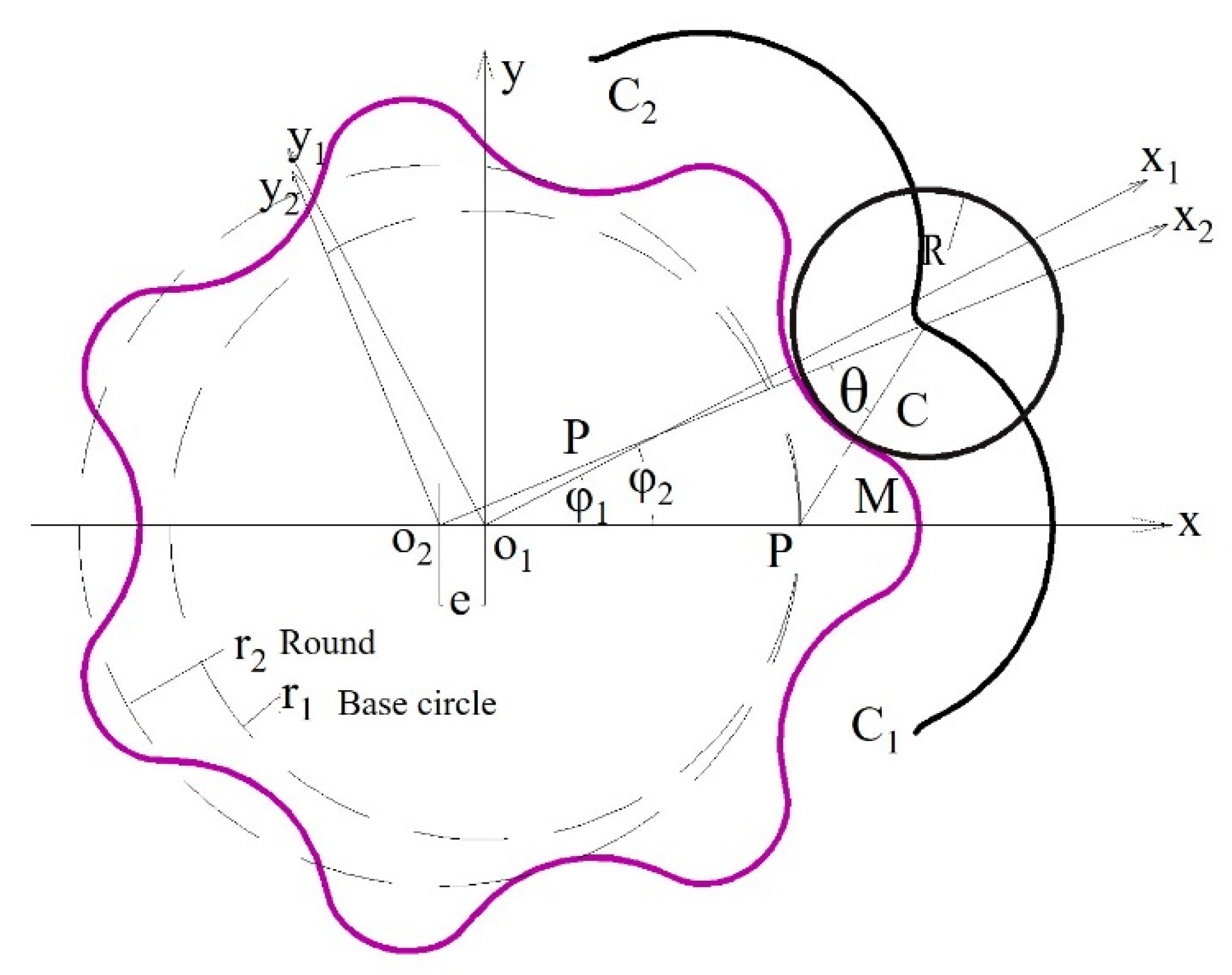
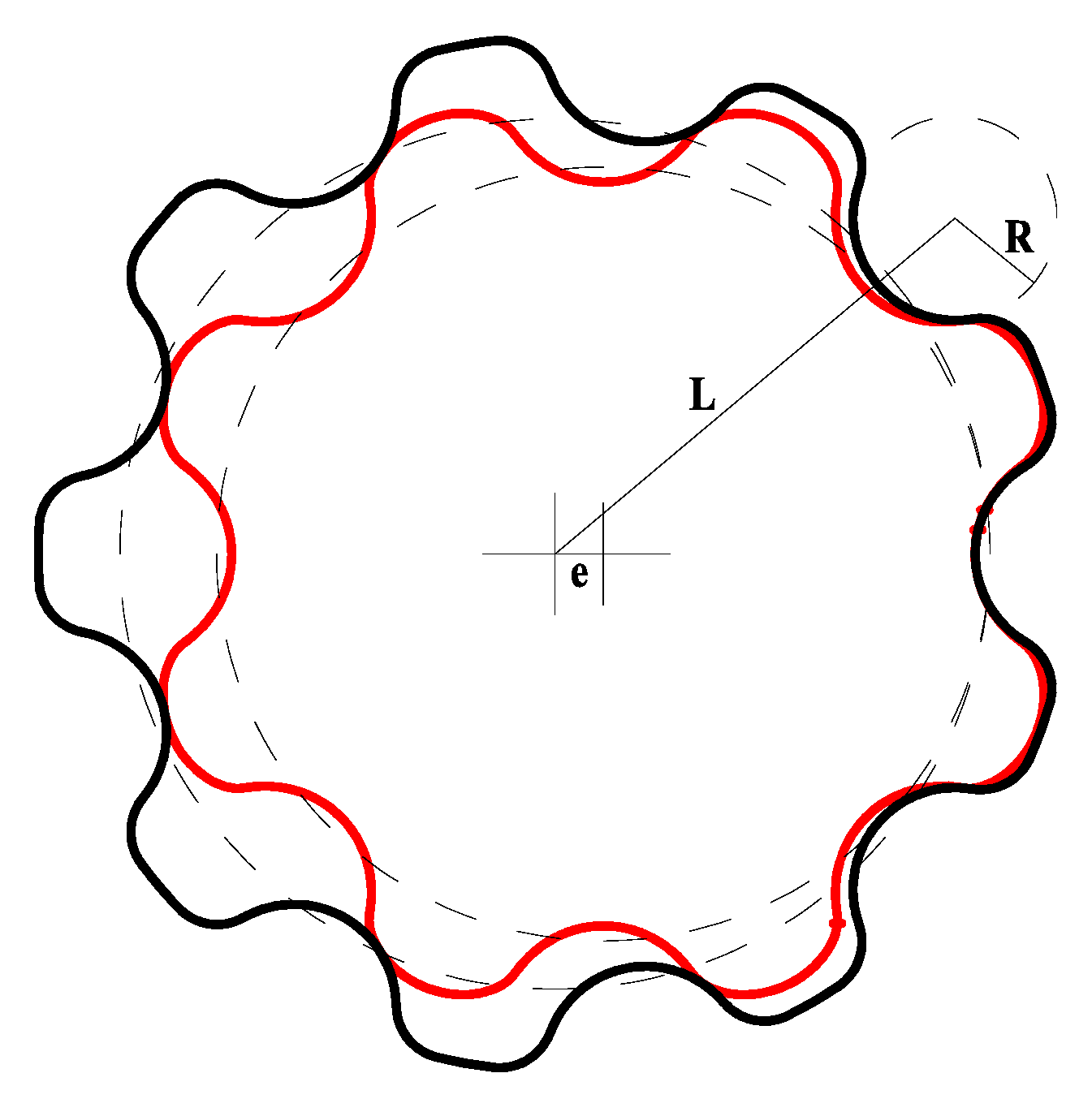
A gerotor pump was designed. The tooth profile was analyzed and designed in line with the requirements of the hydraulic system for hybrid transmission;
(2)
NSGA-II algorithm was employed to optimize the design of tooth profile parameters according to the mathematical model of instantaneous flow. The parameters of the gerotor pump can be determined;
(3)
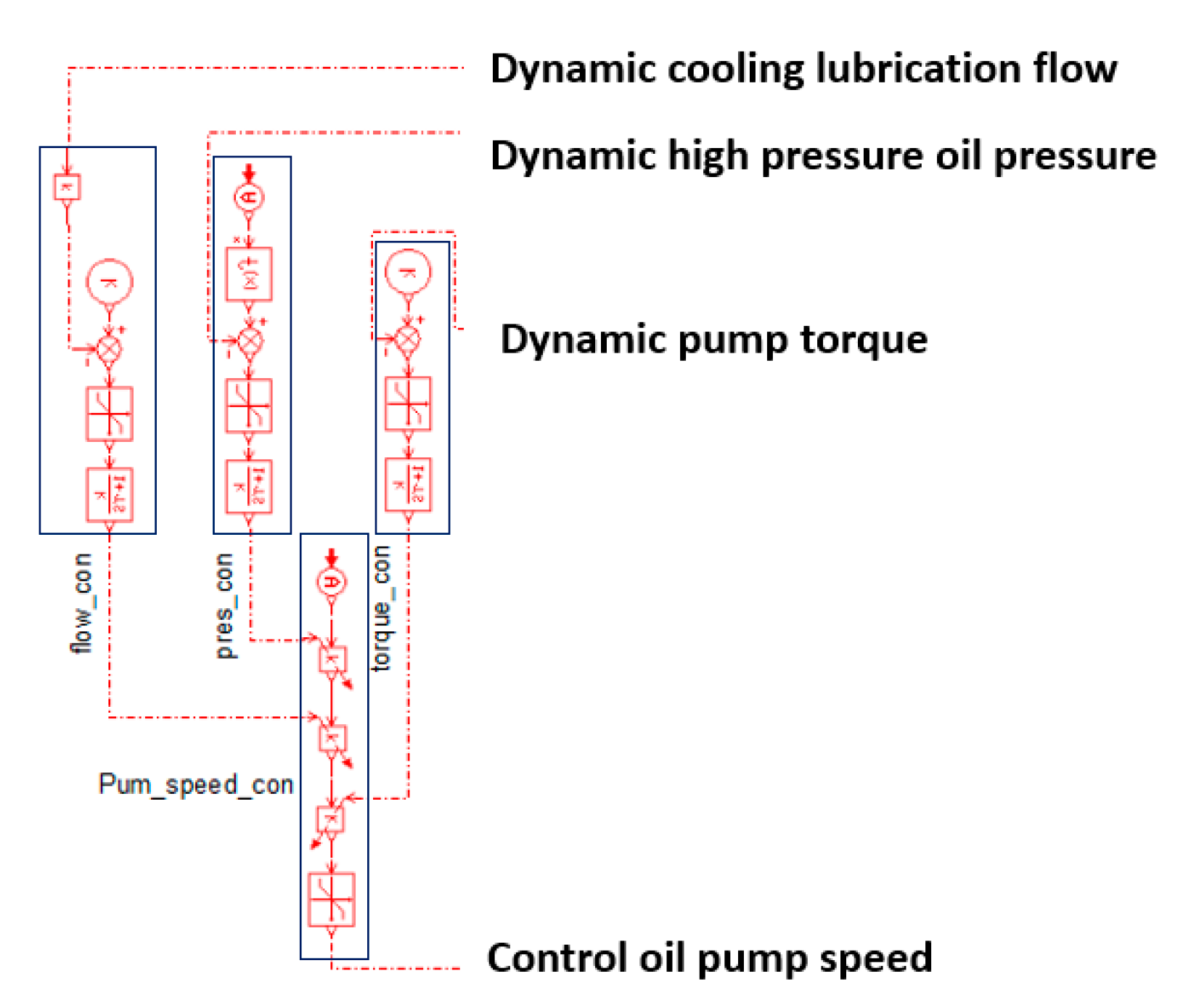
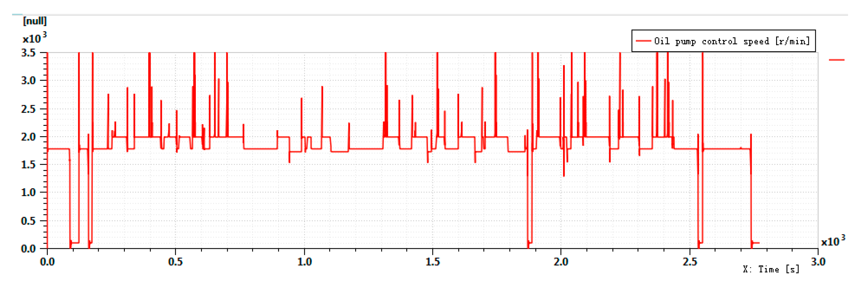
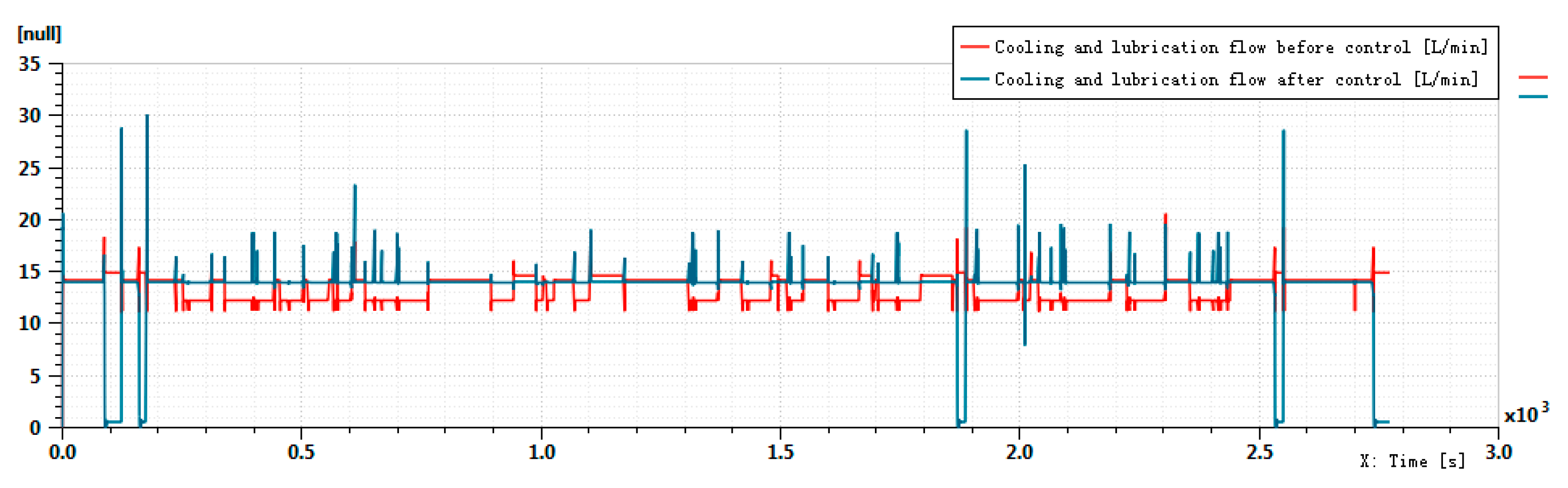
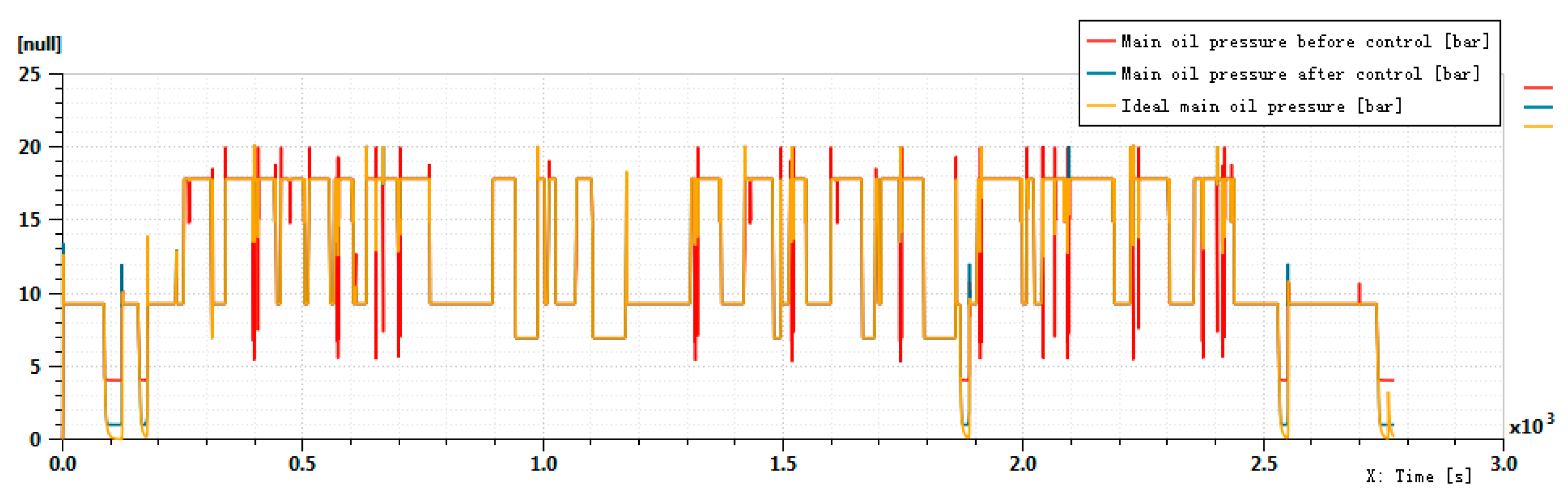
Based on the AMESim platform, a PD control strategy was employed to develop the oil pump speed control model of the oil supply system. In addition, the influence of the designed gerotor pump on the performance of the oil supply system was simulated;
(4)
Prototypes were made, an oil pump test platform was built, and oil pump unit tests were conducted to confirm the rationality of the oil pump design and simulation reliability. Besides, the designed oil pump can meet the functional requirements of a hybrid transmission.

Author Contributions

Conceptualization, M.H. and F.Z.; methodology, M.H.; validation, C.S. and Y.Z.; resources, M.H. and F.Z.; writing—original draft, C.S. and J.Z.; writing—review and editing, F.Z. All authors have read and agreed to the published version of the manuscript.

Funding

This research was supported by A Priority Academic Program Development of Jiangsu Higher Education Institutions (PAPD); Engineering Research Center for Harmless Treatment and Resource Utilization of Aluminum Ash and Slag Solid Waste in Jiangsu Province; The Basic Scientific Research Project of Nantong City (grant number: JC2021200).

Institutional Review Board Statement

Not applicable.

Informed Consent Statement

Not applicable.

Data Availability Statement

Not applicable.

Acknowledgments

Sincere thanks go to anonymous reviewers for their valuable comments and great suggestions to improve this article. Thanks to Corun Hybrid Technology Co., Ltd. for providing the experimental conditions and simulation platform.

Conflicts of Interest

The authors declare no conflict of interest.

References

  1. Tang, X.; Zhang, D.; Liu, T.; Khajepour, A.; Yu, H.; Wang, H. Research on the energy control of a dual-motor hybrid vehicle during engine start-stop process. Energy 2019, 166, 1181–1193. [Google Scholar] [CrossRef]
  2. Fletcher, T.; Thring, R.; Watkinson, M. An Energy Management Strategy to concurrently optimise fuel consumption & PEM fuel cell lifetime in a hybrid vehicle. Int. J. Hydrog. Energy 2016, 41, 21503–21515. [Google Scholar]
  3. Xu, X.; Dong, P.; Liu, Y.; Zhang, H. Progress in automotive transmission technology. Automot. Innov. 2018, 1, 187–210. [Google Scholar] [CrossRef] [Green Version]
  4. Chung, C.T.; Wu, C.H.; Hung, Y.H. Effects of electric circulation on the energy efficiency of the power split e-CVT hybrid systems. Energies 2018, 11, 2342. [Google Scholar] [CrossRef] [Green Version]
  5. Guo, W.; Xu, X.; Liu, X. Cooperative control of P2 hybrid system. J. China Highw. 2018, 31, 308–316. [Google Scholar]
  6. Zhang, Y.; Yang, Y.; Li, L. Brake energy recovery strategy for hybrid vehicles with dual-motor hybrid configuration. China Mech. Eng. 2019, 30, 1631–1637. [Google Scholar]
  7. Kanayama, T.; Yanagida, E.; Kano, S. Development of New Hybrid System for Mid-Size SUV. SAE Int. J. Adv. Curr. Pract. Mobil. 2020, 2, 3356–3363. [Google Scholar]
  8. Mayet, C.; Welles, J.; Bouscayrol, A.; Hofman, T.; Lemaire-Semail, B. Influence of a CVT on the fuel consumption of a parallel medium-duty electric hybrid truck. Math. Comput. Simulat. 2019, 158, 120–129. [Google Scholar] [CrossRef]
  9. Taniguchi, M.; Yashiro, T.; Takizawa, K. Development of New Hybrid Transaxle for Compact-Class Vehicles; SAE Technical Papers 2016-01-1163; SAE: Warrendale, PA, USA, 2016. [Google Scholar]
  10. Du, A.; Liu, K.; Zhu, Z. Structural optimization of single-mode composite power split hybrid power system. China Mech. Eng. 2015, 26, 2976–2981. [Google Scholar]
  11. Lian, J.; Han, H.; Li, L. Research on control strategy of hybrid electric vehicle based on optimal transmission system efficiency. J. Dalian Univ. Technol. 2013, 53, 666–670. [Google Scholar]
  12. Miyachi, E.; Ishiguro, M.; Mizumoto, K. Development of Electric Oil Pump; SAE Technical Papers 2006-01-1595; SAE: Warrendale, PA, USA, 2006. [Google Scholar]
  13. Ma, K.; Sun, D.; Sun, G.; Kan, Y.; Shi, J. Design and efficiency analysis of wet dual clutch transmission decentralised pump-controlled hydraulic system. Mech. Mach. Theory 2020, 154, 104003. [Google Scholar] [CrossRef]
  14. Liu, Y.; Zhou, Y.; Qu, D.; Zhang, F.; Bao, X. Electric oil pump design of hybrid continuously variable transmission. IET Electr. Power App. 2019, 13, 1089–1096. [Google Scholar] [CrossRef]
  15. Suzuki, Y.; Nishimine, A.; Baba, S.; Miyasaka, K.; Tsuchida, M.; Endo, H.; Yamamura, N.; Miyazaki, T. Development of New Plug-in Hybrid Transaxle Forcompact-Class Vehicles; SAE Technical Papers 2017-01-1151; SAE: Warrendale, PA, USA, 2017. [Google Scholar]
  16. Nozawa, N.; Maekawa, T.; Nozawa, S.; Asakura, K. Development of power control unit for compact-class vehicle. SAE Int. J. Passeng. Cars-Electron. Electr. 2009, 2, 376–382. [Google Scholar] [CrossRef]
  17. Fushiki, S. The new generation front wheel drive hybrid system. SAE Int. J. Altern. Powertrains 2016, 5, 109–114. [Google Scholar] [CrossRef]
  18. Furukawa, T.; Lbaraki, R.; Kimura, H.; Baba, S.; Tsuchida, M.; Mizutani, T.; Endo, H.; Kimura, H. Development of New Hybrid Transaxle for Subcompact-Class Vehicles; SAE Technical Papers 2012-01-0623; SAE: Warrendale, PA, USA, 2012. [Google Scholar]
  19. Ichikawa, S.; Takeuchi, H.; Fukuda, S.; Tomita, Y.; Suzuki, Y.; Hirasawa, T. Development of new plug-in hybrid system for compact-class vehicle. SAE Int. J. Altern. Powertrains 2017, 6, 95–102. [Google Scholar] [CrossRef]
  20. Xu, Q.; Sun, J.; Ye, X.; Wang, Z.; Liu, X.; Wang, H. Optimized parameters sizing between EVT and THS used for hybrid electric vehicles. In Proceedings of the 2017 IEEE Transportation Electrification Conference and Expo, Asia-Pacific (ITEC Asia-Pacific), Harbin, China, 7–10 August 2017; IEEE: Piscataway, NJ, USA, 2017; pp. 1–5. [Google Scholar]
  21. Zhang, X.; Li, S.E.; Peng, H.; Sun, J. Design of multimode power-split hybrid vehicles—A case study on the voltec powertrain system. IEEE Trans. Veh. Technol. 2016, 65, 4790–4801. [Google Scholar] [CrossRef]
  22. Kim, N.; Choi, S.; Jeong, J.; Vijayagopal, R.; Stutenberg, K.; Rousseau, A. Vehicle level control analysis for Voltec powertrain. World Electr. Veh. J. 2018, 9, 29. [Google Scholar] [CrossRef] [Green Version]
  23. Okuda, K.; Yasuda, Y.; Adachi, M.; Tabata, A.; Suzuki, H.; Takagi, K.; Atarashi, T.; Horie, R. Development of multi stage hybrid transmission. SAE Int. J. Altern. Powertrains 2017, 6, 77–83. [Google Scholar] [CrossRef]
  24. Zhang, X.; Zhang, A.; Duan, X. Development and Application of Guangqi Electric and Mechanical Coupled System (G-MC). J. Chongqing Univ. Technol. 2019, 33, 50–55. [Google Scholar]
  25. Ni, J.; Han, B. Design and dynamic simulation of hydraulic system of hybrid transmission. J. Adv. Mech. Des. Syst. 2011, 8, 121–123. [Google Scholar]
  26. Schweiger, W.; Schoefmann, W.; Vacca, A. Gerotor pumps for automotive drivetrain applications: A multi domain simulation approach. SAE Int. J. Passeng. Cars-Mech. Syst. 2011, 4, 1358–1376. [Google Scholar] [CrossRef]
  27. Qu, D.; Luo, W.; Liu, Y.; Fu, B.; Zhou, Y.; Zhang, F. Simulation and experimental study on the pump efficiency improvement of continuously variable transmission. Mech. Mach. 2019, 131, 137–151. [Google Scholar] [CrossRef]
  28. Qi, F.; Dhar, S.; Nichani, V.H. A CFD study of an electronic hydraulic power steering helical external gear pump: Model development, validation and application. SAE Int. J. Passeng. Cars-Mech. Syst. 2016, 9, 346–352. [Google Scholar] [CrossRef]
  29. Zhang, D.; Perng, C.Y.; Laverty, M. Gerotor oil pump performance and flow/pressure ripple study. SAE Trans. 2006, 115, 204–209. [Google Scholar]
  30. Esfe, M.H.; Hajmohammad, H.; Moradi, R.; Arani, A.A.A. Multi-objective optimization of cost and thermal performance of double walled carbon nanotubes/water nanofluids by NSGA-II using response surface method. Appl. Eng. 2017, 112, 1648–1657. [Google Scholar]
  31. Vo-Duy, T.; Duong-Gia, D.; Ho-Huu, V. Multi-objective optimization of laminated composite beam structures using NSGA-II algorithm. Compos. Struct. 2017, 168, 498–509. [Google Scholar] [CrossRef] [Green Version]
  32. Elarbi, M.; Bechikh, S.; Gupta, A. A new decomposition-based NSGA-II for many-objective optimization. IEEE Trans. Syst. Man Cybern. Syst. 2017, 48, 1191–1210. [Google Scholar] [CrossRef]
  33. Ni, H.; Zhang, J.; Zhao, N.; Wang, C.; Lv, S.; Ren, F.; Wang, X. Design on the Winter Jujubes Harvesting and Sorting Device. Appl. Sci. 2019, 9, 5546. [Google Scholar] [CrossRef] [Green Version]
  34. Ni, H.; Zhang, J.; Lv, S.; Wang, X.; Pei, Y.; Li, F. Coating Process Parameters and Structural Properties of the Tubular Electrodes of Fuel Cells Based on a Self-Made Coating Device. Coatings 2020, 10, 830. [Google Scholar] [CrossRef]
  35. Sun, N.; Yang, T.; Fang, Y. Transportation Control of Double-Pendulum Cranes with a Nonlinear Quasi-PID Scheme: Design and Experiments. IEEE Trans. Syst. Man Cybern. Syst. 2018, 49, 1408–1418. [Google Scholar] [CrossRef]
  36. Vasiliu, N.; Vasiliu, D.; Călinoiu, C.; Puhalschi, R. Simulation of Fluid Power Systems with Simcenter Amesim; CRC Press: Boca Raton, FL, USA, 2018; pp. 10–15. [Google Scholar]
Figure 1. Three integration modes: (a) single-motor single-pump, (b) single-motor dual-pump, and (c) dual-motor dual-pump.
Energies 14 05649 g001
Figure 2. Schematic diagram of the total success rate of the oil pump.
Energies 14 05649 g002
Figure 3. Rotor tooth profile.
Energies 14 05649 g003
Figure 4. Pareto optimal solution.
Energies 14 05649 g004
Figure 5. Rotor tooth profile.
Energies 14 05649 g005
Figure 6. Pressure cloud diagram.
Energies 14 05649 g006
Figure 7. Pressure pulsation.
Energies 14 05649 g007
Figure 8. Prototype for testing.
Energies 14 05649 g008
Figure 9. Diagram of oil pump flow requires and supply.
Energies 14 05649 g009
Figure 10. Speed control module: low_con is the control of flow; pres_con is the control of pressure; torque_con is the control of torque and Pum_speed_con is the control of pump speed.
Energies 14 05649 g010
Figure 11. Oil pump control speed.
Energies 14 05649 g011
Figure 12. Comparison of cooling and lubrication flow before and after control.
Energies 14 05649 g012
Figure 13. Comparison of main oil pressure before and after control.
Energies 14 05649 g013
Table 1. High-pressure pump displacement test data.
Test ConditionsPressure: 0 Bar Theoretical Displacement: 4 mL/r
Oil Pump NumberRotating Speed
(r/min)
Flow
(L/min)
Calculated Displacement
(mL/min)
Deviation
(%)
1#10003.853.853.75%
15005.83.873.25%
2#10003.843.844%
15005.83.873.25%
Table 2. Low-pressure pump displacement test data.
Test ConditionsPressure: 0 Bar Theoretical Displacement: 8 mL/r
Oil Pump NumberRotating Speed
(r/min)
Flow
(L/min)
Calculated Displacement
(mL/min)
Deviation
(%)
1#10007.97.901.25%
150011.87.871.63%
2#10007.97.901.25%
150011.87.871.63%
Publisher’s Note: MDPI stays neutral with regard to jurisdictional claims in published maps and institutional affiliations.

