Article

RANS- and TFC-Based Simulation of Turbulent Combustion in a Small-Scale Venting Chamber

by
Justina Jaseliūnaitė
*,
Mantas Povilaitis
* and
Ieva Stučinskaitė
Laboratory of Nuclear Installation Safety, Lithuanian Energy Institute, Breslaujos Str. 3, LT-44403 Kaunas, Lithuania
*
Authors to whom correspondence should be addressed.
Energies 2021, 14(18), 5710; https://doi.org/10.3390/en14185710
Submission received: 5 August 2021 / Revised: 4 September 2021 / Accepted: 8 September 2021 / Published: 10 September 2021

Abstract

:
A laboratory-scale chamber is convenient for combustion scenarios in the practical analysis of industrial explosions and devices such as internal combustion engines. The safety risks in hazardous areas can be assessed and managed during accidents. Increased hydrogen usage in renewable energy production requires increased attention to the safety issues since hydrogen produces higher explosion overpressures and flame speed and can cause more damage than methane or propane. This paper reports numerical simulation of turbulent hydrogen combustion and flame propagation in the University of Sydney's small-scale combustion chamber. It is used for the investigation of turbulent premixed propagating flame interaction with several solid obstacles. Obstructions in the direction of flow cause a complex flame front interaction with the turbulence generated ahead of it. For numerical analysis, OpenFOAM CFD software was chosen, and a custom-built turbulent combustion solver based on the progress variable model—flameFoam—was used. Numerical results for validation purposes show that the pressure behaviour and flame propagation obtained using RANS and TFC models were well reproduced. The interaction between larger-scale flow features and flame dynamics was obtained corresponding to the experimental or mode detailed LES modelling results from the literature. The analysis revealed that as the propagating flame reached and interacted with obstacles and the recirculation wake was created behind solid obstacles, leaving traces of an unburned mixture. The expansion of flames due to narrow vents generates turbulent eddies, which cause wrinkling of the flame front.

Graphical Abstract

1. Introduction

There is an increasing range of investigated future applications of hydrogen with the increasing focus on sustainable energy [1]. Hydrogen is sought to replace hydrocarbons as a sustainable energy carrier [2], and hydrogen-powered vehicles are being actively developed and tested [3,4].
Increasing the use of hydrogen necessitates managing the risks it poses. If hydrogen was to leak in a confined or semi-confined environment, it would form a combustible mixture with air. Depending on the conditions, this mixture could pose explosive combustion or even detonation risk. Hydrogen produces higher explosion overpressures, flame speed and can cause more damage than methane or propane.
In the worst-case scenario, a large premixed cloud of the combustible hydrogen–air mixture would form in the confined volume. The flame would propagate in this cloud from the ignition point. Interaction of flame and induced flow with the structural elements and other obstacles would result in turbulence generation. Interaction between the turbulence and flame could accelerate the latter, creating pressure shocks.
Premixed turbulent combustion problem is difficult due to complex interactions between fluid dynamics, mass/heat transport and chemistry. There are still unknowns in understanding the mechanisms of premixed turbulent combustion, and the prediction of the flame propagation velocity remains an unsolved issue, largely because of the issue of flame–turbulence interaction. The flame–turbulence interaction is responsible for the burning rate, the rate of pressure increase and achieved overpressure, the geometry of accelerating flame front and resulting structures in the flow field.
Researchers have studied various configurations in which the flame propagates through obstacles, inducing turbulence. Turbulence amplification results in fast propagation speeds and intense combustion [5]; therefore, accelerated flames drive pressure waves with large overpressure [6]. The burning rate grows due to the creation of vortical structures which stretch the burning surface area, thus increasing it [7].
More obstacles resulting in a higher blockage ratio give rise to more pronounced turbulence and a faster flame [8]. It can be explained by an increased number of vortical structures in the flow. The form of the obstruction is also important; sharp geometric edges induce the formation of vortex and vortex shedding, which result in strong mixing [7].
This paper reports numerical simulation of turbulent hydrogen combustion and flame propagation in the University of Sydney's vented small-scale combustion chamber. A laboratory-scale chamber is convenient for combustion simulation at higher resolution, allowing the study of the interaction between the flame and main flow structures in higher detail.
The simulations were performed using OpenFOAM and flameFoam—a custom open source computational fluid dynamics (CFD) solver developed by the authors for the simulation of premixed turbulent combustion in hydrogen–air mixtures. There are simulations of combustion in vented small-scale chambers published in the literature with turbulence modelled according to the Large Eddy Simulation (LES) approach [8,9,10,11,12]. Furthermore, mentioned research papers investigates sensitivity to the ignition source [8], comparison of mixtures [9,12], analysis of the equivalence ratio effect [11] and different configurations of baffles [9,10,12]. Most of them show flame front structure. However, there is a lack of analysis of the interaction of the flame front with obstacles and the resulting larger-scale flow structures.
LES has a superior predictive capability compared to the unsteady Reynolds-averaged Navier–Stokes (URANS) approach; however, it is much more computationally demanding. Therefore, RANS usage is widespread in practical applications, where the computational cost of LES becomes prohibitive. Even when combustion takes place in large-volume compartments—for example, containments of nuclear power plants—strong flame acceleration cannot be excluded and needs to be treated reliably [13]. However, due to the simplified turbulence treatment in the URANS case, simulation accuracy can be limited, and the approach needs to be extensively validated.
Validation motivates comparative numerical research based on the RANS method connected to turbulent flame propagation experiments. In relation to obstacle-driven turbulent flame acceleration, the RANS method suitability has been demonstrated in a number of cases. For example, in several works by different authors [14,15,16,17], numerical simulations of hydrogen flame propagation in a large-scale facility—ENACCEF acceleration tube—was performed employing URANS, and turbulent flame speed closure approaches with varying but generally satisfactory accuracy. In [18], URANS based simulations were used to investigate the deflagration to detonation transition (DDT) process in a channel with arc obstacles. Tolias et al. [19] investigated and compared LES and URANS models for medium-scale hydrogen deflagration modelling and came up with many benefits URANS may have over the LES; for example, URANS models are easier to apply, and they are more effective.
Up to now, there is a belief that URANS is used for large- or medium-scale experiments and mostly for application/practical or optimisation needs. Nevertheless, there are researches that suggest it can be not only effective but also accurate in modelling combustion phenomena and predicting flame structure in small-scale facilities. For example, URANS based simulations were validated and employed to perform a detailed study of interactions between the flame and flow in a duct with obstacles [20]. Another recent work, [21], validated and used the URANS approach to study the mechanism behind DDT in hydrogen–air mixtures in a channel with obstacles. In [22], a need for partial flame-quenching model inclusion into the URANS-based application-oriented modelling of accelerating H2–CO–air flames in obstructed channels was evaluated based on DNS and experimental data. A recent review of CFD application in process safety [23] also lists a number of URANS method applications for combustion cases, including interacting with obstacles.
Satisfactory validation cases of flame–obstacle interactions present in mentioned and other works encourage the further application of the URANS approach to practical and analytical studies. However, given turbulence treatment simplifications present in RANS, the universality of validation results can be questioned. Furthermore, turbulence–flame interaction, responsible for the flame acceleration in the URANS case, is often modelled by parametrising turbulent burning velocity on computed turbulence parameters, increasing accuracy demand on turbulence simulation. Therefore, to maintain a level of confidence in the methodology, validation in each specific case should be sought.
Simulation of small case chamber using URANS approach allows checking if the obtained results are comparable not only to the experiment but to the LES approach as well. At the same time, since larger flow structures can be resolved in the RANS case as well, and interaction of small-scale turbulence and flame is parametrised through a combustion model; successful analysis of such case still allows studying the interaction of the flame front with obstacles and the resulting larger-scale flow structures and flame acceleration due to turbulence.

2. Methodology

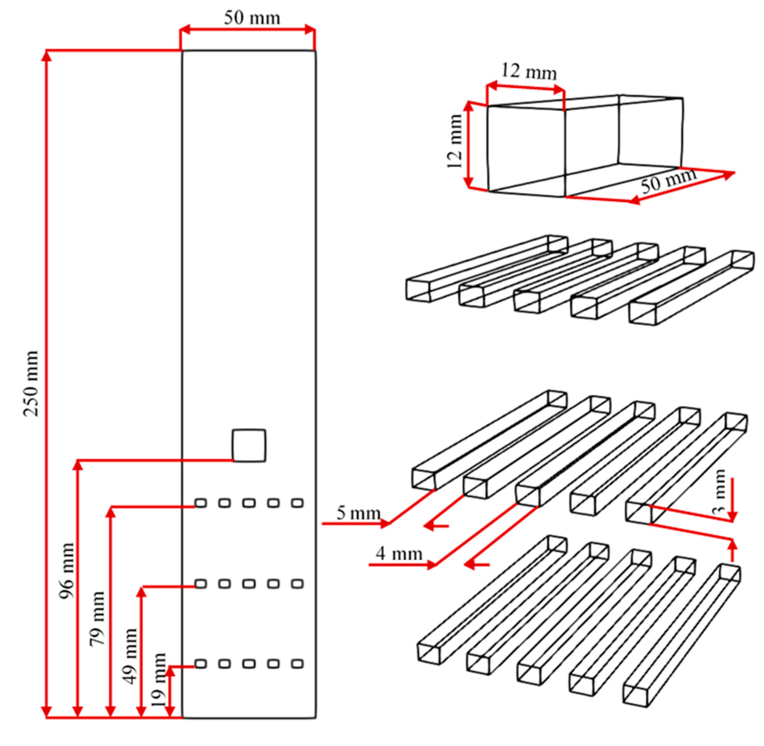
2.1. The Laboratory-Scale Chamber

The experimental test case from the University of Sydney is used here for an analysis of turbulent hydrogen combustion. The schematic diagram of the laboratory-scale combustion chamber is shown in Figure 1. The chamber measures 50 × 50 × 250 mm with a total volume of 0.625 litres. The chamber is equipped with three rows of baffles with five 3 mm thick and 4 mm wide strips separated by 5 mm gaps which give an area blockage of 0.4. Each row of baffles is placed at 19 mm, 49 mm and 79 mm from the ignition source at the base of the chamber. The small solid obstacle has a square cross-section of 12 × 12 mm and is placed at 96 mm from the base of the chamber [9].
Hydrogen and air enter the chamber through a non-return valve at atmospheric pressure, and the mixture is left to settle before the ignition. A moment before ignition, the flap at the top of the chamber is opened and remains opened during the whole process to allow venting. In the experiment, the mixture is ignited by focusing an infrared output from an Nd-YAG laser 2 mm above the base. One of the Keller-type PR21-SR piezo-electric pressure transducers is placed in the base of the chamber and the other one is located in the wall, 64 mm from the top.
Flame propagates from the ignition point upwards and is accelerated by the turbulence induced when flame encounters and interacts with obstacles present in the chamber. According to the numerical flow velocities, Re number reaches values up to and around 106 in the chamber, while Ret ranges from several hundred to thousands during main acceleration.

2.2. flameFoam

Numerical calculations of premixed turbulent flame propagating past repeated obstructions were performed using a custom-built solver—flameFoam—built using OpenFOAM toolkit. Solver is partially based on buoyantPimpleFoam, rhoPimpleFoam chtMultiRegionFoam solvers. OpenFOAM does not have any solver based on a progress variable and turbulent flame-speed closure approaches. flameFoam is publicly hosted on https://github.com/flameFoam/flameFoam (accessed on 4 September 2021). The governing equations are compressible Navier–Stokes equations. Solved conservation equations for mass, momentum and energy are as follows:
ρ t + Δ   · ( ρ U ) = 0 ,
ρ U t + Δ · ( ρ U × U ) = · τ e f f p + ρ g ,
ρ h t + Δ · ( ρ U h ) + ρ K t + Δ · ( ρ U K ) = p t + · ( α e f f h ) + ρ ( g · U ) + S h ( S c ) ,
where ρ —density, t —time, U —velocity, τ e f f —shear stress, p —pressure, g —gravitational acceleration, h —enthalpy, K —kinetic energy, α e f f —effective thermal diffusivity, S h —enthalpy source, S c —combustion source.
Combustion in the solver is modelled using a transport equation for the progress variable (Equation (4)) and the turbulent flame-speed closure (TFC) approach [24]. TFC is a simplified (compared to chemistry simulation) method with the source term expressed through the turbulent flame speed S t (Equation (5)), suitable and extensively used for practice-oriented simulations and research where this method has been demonstrated to be appropriate. The turbulent flame speed S t is usually estimated using empirical or analytical correlations with turbulence parameters or using a more complex approach.
ρ c t + Δ · ( ρ U c ) = · ( μ E f f S c T c ) + S c ,
S c = ρ u S T | c | ,
where c —progress variable, μ e f f   —effective dynamic viscosity, S c T —turbulent Schmidt number.
Modelling using RANS and TFC approaches has been validated in the literature for a number of different cases—flame interaction with obstacle-induced turbulence [14,15,16,17,25,26], fan-stirred explosion bomb [27], slow deflagrations [28], upwards hydrogen flame propagation in larger closed volume [29], combustion in pipelines [30] and fan-stirred combustion vessel [31].
The progress variable is defined as:
c = Y 0 H 2 Y H 2 Y 0 H 2 Y H 2 ,
where Y 0 H 2 —initial hydrogen mass fraction, Y H 2 —hydrogen mass fraction, Y H 2 —assumed final hydrogen mass fraction.
Progress variable can have values from the interval 0 ≤ c ≤ 1; value 0 denotes unburnt mixture, while value 1—burned mixture.
Turbulent flame speed was evaluated using Bradley correlation [32]
S T = u 0.88 ( K a   L e ) 0.3 ,
where u —RMS velocity, K a —Karlovitz stretch factor, L e —Lewis number.
Where fluctuating velocity:
u = ( 2 3 k ) 1 2 ,
where k —turbulent kinetic energy.
Karlovitz stretch factor [32]
K a = 0.157 ( u S L ) 2 R e T 1 2 ,
R e T = u l t B ν ,
l t B = ( 3 2 ) 3 2 u 3 ε ,
where S L —laminar flame speed, R e T —turbulent Reynolds number, ν —kinematic viscosity, l t B —Bradley turbulent length scale, ε —turbulent dissipation rate.

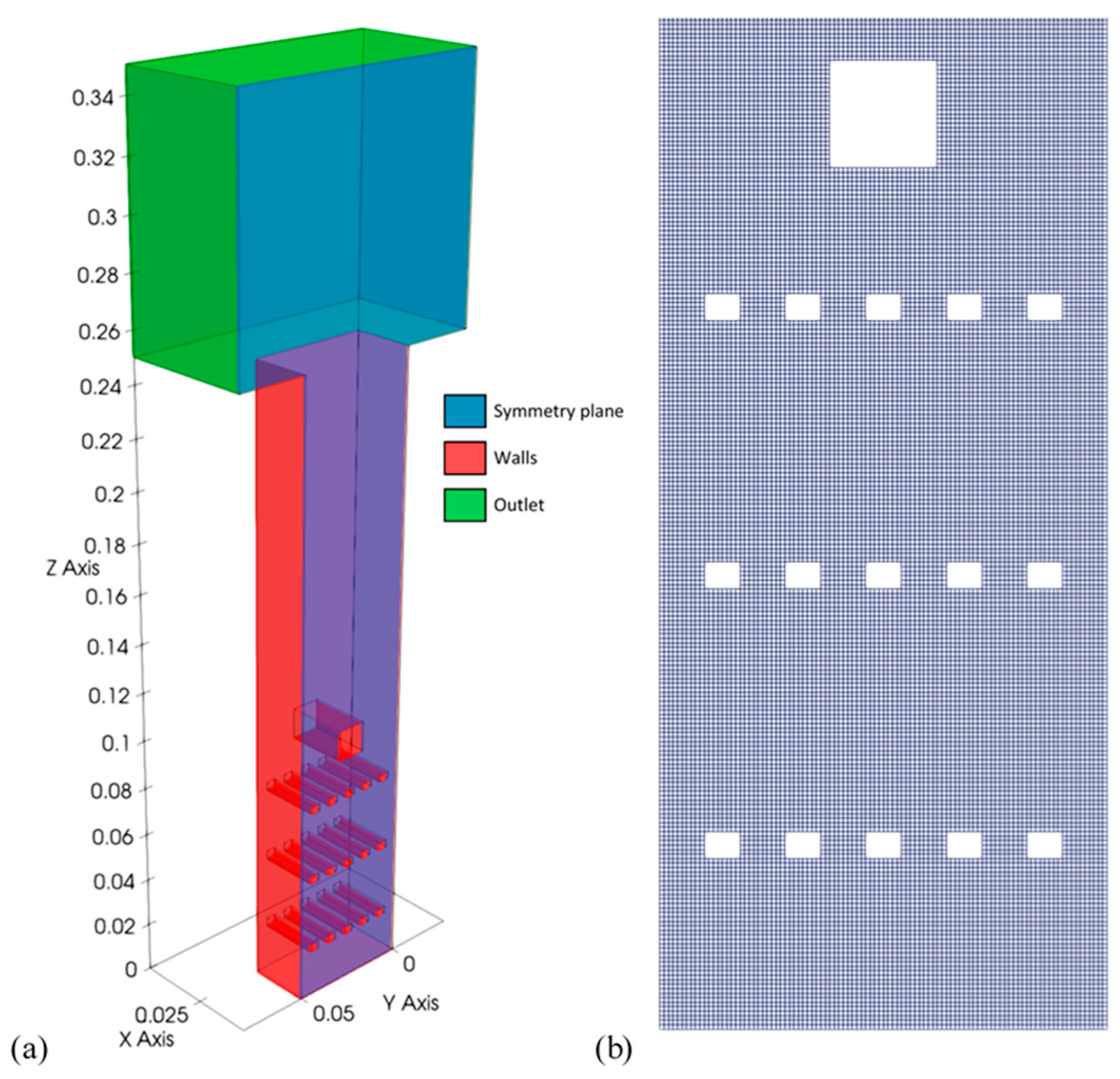
2.3. Initial and Boundary Conditions

The present study focuses on the hydrogen–air mixture; it constitutes 22.65% of H2 and 77.35% of air. In the experiments, the hydrogen–air mixture is injected and allowed to rest. Therefore, initial turbulence is considered negligible and initial turbulence parameters were set as extremely low values (e.g., 0.001 m2/s2 for turbulent kinetic energy). Since the laminar combustion regime is not modelled, ignition was initiated by imposing an ignition radius of 0.0055 m at the bottom of the chamber. Initial conditions are selected according to the experiment; they are shown in Table 1. Model constants are selected according to literature, while thermophysical properties depending on the initial composition of the mixture were calculated using an open-source suite of tools, Cantera [33]. Complete combustion was assumed, and the final hydrogen mass fraction was set to 0.
The computational domain of the chamber has dimensions of 25 × 50 × 250 mm, with a symmetrical boundary condition in the x–z plane. While turbulence is inherently non-symmetric, experimental images do not display significant deviation from symmetric flame [8]; therefore, this assumption should not significantly distort simulation results. The chamber domain constitutes 50 × 100 × 500 cells in the x, y and z directions, respectively. The grid is structured and uniform, giving a grid size of Δ = 0.5 mm. It is extended to 350 mm in the z direction and to 30 mm in the x and y directions at the top of the facility to facilitate venting simulation. For the present study configuration, BBBS—three rows of baffles located starting near the ignition and a small square obstacle after baffles—was used. The computational domain is presented in Figure 2.
Turbulence was modelled using k-ω SST model [34]. k-ω-SST is composed of two zonally blended models—k-ε and k-ω. These two models are dynamically blended during the simulation since the k-ω model is more suitable for wall-bounded flows and k-ε for free stream flows. This allows the k-ω SST model to appropriately describe turbulence in both zones, while the separately used k-ε model would perform worse than k-ω in the logarithmic region in equilibrium adverse pressure gradient flows. On the other hand, the standard k-ω model is sensitive to free stream conditions and is not suitable for turbulence simulation in the region further from the surfaces.
Adiabatic and no-slip boundary conditions were employed on the chamber walls and obstacles. Boundaries of the expanded upper part above the chamber were considered as outlets. Standard OpenFOAM boundary conditions for turbulence parameters at surfaces were used—kqRWallFunction (zero gradient wrapper) for turbulent kinetic energy, omegaWallFunction for specific turbulent dissipation rate and a wall-function automatically calculating ω with viscous and inertial sublayer expressions depending on y+. nutkWallFunction was used for eddy viscosity boundary at surfaces, wall functions based on k and automatically calculating viscous and inertial sublayer expressions depending on y+. Pressure and temperature were set to room values, and the standard OpenFOAM outlet condition was used for velocity and turbulence parameters at the outlet boundary.
The time step was automatically adjusted during the simulation run to keep the Courant number under 0.75. The simulation was performed using the Euler time discretisation scheme, and model equations were discretised using the Gauss linear scheme for gradients, second-order linear-upwind scheme for velocity, first-/second-order limited linear for turbulence parameters and second-order Van Leer scheme for scalars.
Two numerical grids have been studied for mesh independence study. Sizes of the numerical grids were Δ = 0.001 m and 0.0005 m, having 866,200 and 6,845,200 cells, respectively. As mentioned before, the ignition radius was 0.0055 m; therefore, pressure evolution cannot be compared due to discrepancies of discrete ignition area shapes between meshes. Nevertheless, velocity field distribution and flame front structure are compared in Figure 3. It is shown that there are no major differences, except that finer mesh gives more details of the flame structure and flow field distribution. As this numerical investigation is focused on the combustion–turbulence interaction, the finer mesh is more appropriate for further research.
With the finer mesh, during the main part of the simulated transient, y+ values were kept mostly between 1 and 5 for the bottom wall and 30 and 70 for the side and front walls and obstacles.

3. Results

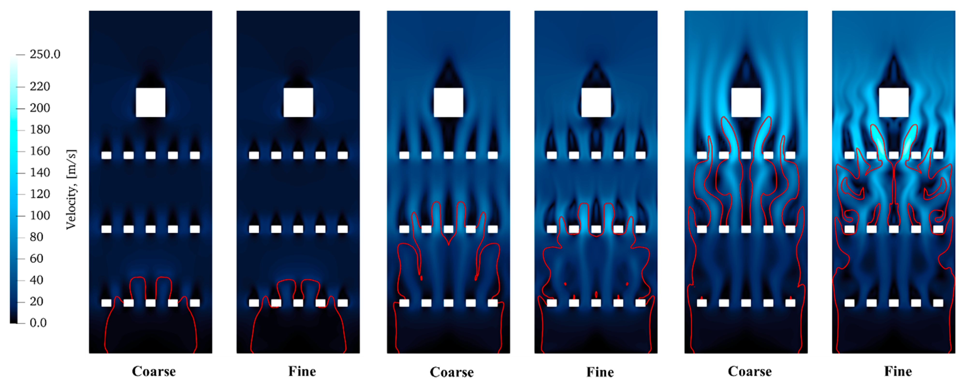
3.1. Comparison with Experimental Results

URANS results presented in this paper are for unsteady turbulent premixed deflagrating flames propagating past obstructions in a chamber. The result of overpressure evolution is given in Figure 4, while Figure 5 presents a comparison of numerical and experimental flame arrival times at different heights.
The pressure was measured in the centre of the base of the chamber. Experimental results were extracted from [8]. The simulation was found to be in good agreement with the experiment. Modelling predicts the first pressure rise at around 3.57 ms, and a pressure peak at 4.3 ms was captured. Afterwards, the overpressure begins to drop.
The pressure rise is not interrupted in numerical results, contrary to the experiment at 4 ms. This stagnation of pressure increase is observed around the moment when flame fingers start to merge behind the small obstacle (at 3.9 ms and 4 ms in Figure 6). Interaction of flames and fresh colder gas in the turbulent environment behind the obstacle might include a high rate of local quenching, which would lower heat production and pressure increase rate. flameFoam does not support quenching simulation yet, and therefore is not able to predict a decrease of combustion rate in this situation. The moment of overpressure peak corresponds to the time just before the flame exits the chamber. This is the moment after which the rate of combustion in the chamber decreases only due to smaller flame surface area (flames near the walls catch up with the flame at the centre) and due to exhaustion of combustible mixture—almost the whole initial mixture has been burnt, except a few small unburnt pockets. The correspondence of maximum overpressure timing with flames reaching the compartment exit has also been shown in the literature [35].
Agreement of flame propagation simulation and experimental results (Figure 5) is very good up to 3.75 ms, which is when interaction with the small obstacle started. Simulations overpredict flame acceleration caused by this interaction, possibly due to missing local quenching modelling.

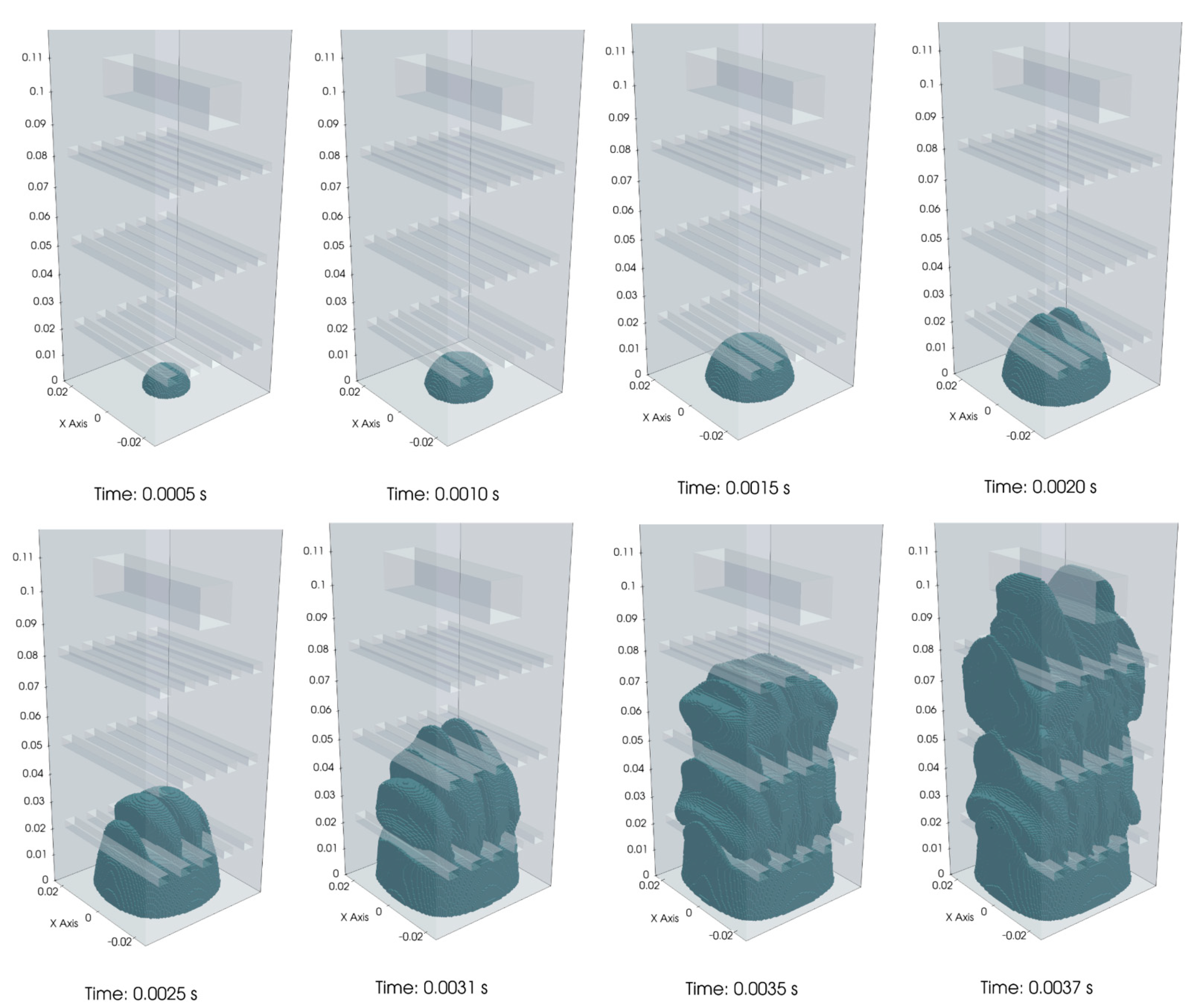
3.2. Study of Flame Propagation

This section’s objective is to illustrate the typical flame behaviour in a vented channel with repeated obstructions. Figure 6 shows a sequence of images of propagating flame development at different times. After the first baffle, the flame tends to propagate in finger-like shapes. Laminar-like fingers correspond to experimental works of Alharbi et al. [36] and Masri et al. [37], where some LIF-OF images of the hydrogen flames are given. This structure is not wrinkled much because the turbulence level is still low. However, expanding unburned mixture generate vortices behind every baffle; consequently, vortices interact with the flame front and distort it.
After passing the second baffle at 3.1 ms, the flame is accelerated and distorted even more due to a strong interaction between vortices and the flame front. Finger-like flame front shapes merge in the middle part of the chamber, resulting in lateral propagation towards the walls.
The evolution of the turbulent flame is shown in Figure 7 in terms of the progress variable. After ignition, the leading edge of the flame front starts to expand hemispherically and elongates in the z direction. Upon reaching the first baffle plate, the hemispherical laminar flame shape is distorted due to protrusion through the narrow vents and starts to roll up; thus, turbulent combustion begins as the flame is compressed and expanded in order to pass through obstacles. As the flame is distorted, the surface area of the flame increases; therefore, more combustible mixture is consumed, and a higher flame propagation velocity develops.
Turbulent structures are generated in the wake of each baffle, which are shown in Figure 8. As it is presented, the intensity of vorticity increases with each obstruction as the flame front propagates through; therefore, stronger vortices produce larger and faster recirculation regions behind the subsequent obstructions, increasing the flame surface and combustion rate. Vortices formed ahead of the flame front wrinkle the flame, thus enhancing the transport of mass and heat and also disrupt the flame.
At 3.5 ms, the leading edge of the flame front reaches the last baffle, as presented in Figure 6 and Figure 7. The flame front forms finger-like shapes again. Nevertheless, this time, fingers do not merge in the middle of the chamber; they are stretched and wrinkled due to induced turbulence. The flame/vortex interaction is clearly seen in the last frame of Figure 8, as the flame initially tries to propagate around the vortex but then is suddenly drawn into the vortex core.
Afterwards, the flame front reaches the square obstacle at 3.7 ms, and from that time, the overpressure increases enormously (see Figure 4). After the flame fingers encounter the square obstacle, they are directed around the obstacle and wrap around it at a very high speed. Although the solid square obstacle does not induce turbulence as much as baffles, it increases the blockage ratio and distorts the development of the flame front. When the flame propagates through the last obstacle, the wrinkled flame front becomes reconnected in the recirculation region, creating a pocket of unburned mixture behind the obstacle, a feature of obstacle–flame interaction expected from the previous experimental work [38], and then the flame spreads towards the chamber exit.
The mentioned/described flame shape evolution was also reproduced in LES studies [8,9,12,39,40], which means that URANS simulation prediction is adequate and it resolves turbulent flow structures. However, none of the LES studies described flame–vortex interaction in detail.
Since the obstacles and vortical structures induced behind them wrinkle the flame and disrupt front continuity, flame pockets consuming remaining unburned gases are formed (visible in Figure 6 as well), a feature of flame and obstacle-induced turbulence interaction confirmed by more detailed LES modelling in previous works [41,42,43]. At the same time, the unburned mixture is trapped near the walls at various stages of combustion. Even at the last shown moment in Figure 6 (t = 4.5 ms), there are several flame/unburned mixture pockets alongside the walls. This could be due to the flame/vortex interaction, which directs the flame front to the centre of the chamber, as well as decreasing flow rates and turbulence towards the walls.

4. Conclusions

The research presented in this paper studied premixed hydrogen–air mixture flame propagation in a small-scale combustion chamber. A custom-built turbulent combustion solver, flameFoam, based on the progress variable model, was applied. According to the numerical results, the solver can adequately reproduce pressure behaviour. The simulation correctly predicted the maximum overpressure of 0.8 bar and its timing. The solver was not able to predict a brief period of pressure stagnation, possibly due to missing support for quenching simulation in flameFoam.
The performed simulation complement the available body of works related to validation of the URANS method application to simulation of the interaction between obstacle-induced turbulence and flame. Relevant suitability and limitations of the flameFoam solver also have been demonstrated.
Flame propagation investigation showed that vortices are formed behind every obstruction. The vorticity intensity increases with further obstacles as the flame front propagates through them due to increased flow and flame velocities. Therefore, the positive feedback loop is formed—with increasing velocities, the flame front is perturbed and stretched by strengthening vortices, thus inducing turbulence as well as increasing burning rate and flame propagation velocity. The flame/vortex interaction results not only in a wrinkled flame front but also the flame being pulled into vortices, consequently intensifying the mixing of the unburned mixture (vortex core) and burned mixture.
Further validation of RANS/TFC simulations of a small chamber with different obstacle configurations is required, including support for local quenching modelling. It would be interesting to perform both RANS and LES simulations with equivalent combustion models to see the actual extent of RANS limitations in given conditions.

Author Contributions

Conceptualisation, M.P.; methodology, M.P. and J.J.; software, M.P. and J.J.; validation, M.P. and J.J.; formal analysis, M.P. and J.J.; investigation, M.P., I.S. and J.J.; writing—original draft preparation, J.J.; writing—review and editing, M.P., I.S. and J.J.; visualisation, J.J.; supervision, M.P. All authors have read and agreed to the published version of the manuscript.

Funding

This research received no external funding.

Institutional Review Board Statement

Not applicable.

Informed Consent Statement

Not applicable.

Data Availability Statement

Not applicable.

Conflicts of Interest

The authors declare no conflict of interest.

References

  1. Nazir, H.; Muthuswamy, N.; Louis, C.; Jose, S.; Prakash, J.; Buan, M.E.; Flox, C.; Chavan, S.; Shi, X.; Kauranen, P.; et al. Is the H2 economy realizable in the foreseeable future? Part III: H2 usage technologies, applications, and challenges and opportunities. Int. J. Hydrogen Energy 2020, 45, 28217–28239. [Google Scholar] [CrossRef]
  2. Møller, K.T.; Jensen, T.R.; Akiba, E.; Li, H.-W. Hydrogen—A sustainable energy carrier. Prog. Nat. Sci.-Mater. 2017, 27, 34–40. [Google Scholar] [CrossRef]
  3. Hosseini, A.E.; Butler, B. An overview of development and challenges in hydrogen powered vehicles. Int. J. Green Energy 2019, 17, 13–37. [Google Scholar] [CrossRef] [Green Version]
  4. Zhang, G.; Zhang, J.; Xie, T. A solution to renewable hydrogen economy for fuel cell buses—A case study for Zhangjiakou in North China. Int. J. Hydrogen Energy 2020, 45, 14603–14613. [Google Scholar] [CrossRef]
  5. Teodorczyk, A.; Lee, J.H.S.; Knystautas, R. The structure of fast turbulent flames in very rough, obstacle-filled channels. In Symposium (International) on Combustion; Elsevier: Orléans, France, 1990; Volume 23, pp. 735–741. [Google Scholar] [CrossRef]
  6. Teodorczyk, A.; Drobniak, P.; Dabkowski, A. Fast turbulent deflagration and DDT of hydrogen–air mixtures in small obstructed channel. Int. J. Hydrogen Energy 2009, 34, 5887–5893. [Google Scholar] [CrossRef] [Green Version]
  7. Coates, A.M.; Mathias, D.L.; Cantwell, B.J. Numerical investigation of the effect of obstacle shape on deflagration to detonation transition in a hydrogen–Air mixture. Combust. Flame 2019, 209, 278–290. [Google Scholar] [CrossRef]
  8. Abdel-Raheem, M.A.; Ibraham, S.S.; Malalasekera, W.; Masri, A.R. Large eddy simulation of hydrogen–air premixed flames in a small scale combustion chamber. Int. J. Hydrogen Energy 2015, 40, 3098–3109. [Google Scholar] [CrossRef]
  9. Elshimy, M.; Ibrahim, S.; Malalasekera, W. Numerical studies of premixed hydrogen/air flames in a small-scale combustion chamber with varied area blockage ratio. Int. J. Hydrogen Energy 2020, 45, 14979–14990. [Google Scholar] [CrossRef]
  10. Gubba, S.R.; Ibrahim, S.S.; Malalasekera, W.; Masri, A.R. LES Modeling of Premixed Deflagrating Flames in a Small-Scale Vented Explosion Chamber with a Series of Solid Obstructions. Combust. Sci. Technol. 2008, 180, 1936–1955. [Google Scholar] [CrossRef] [Green Version]
  11. Yehia, M.; Abdel-Aziz, F.; Hassan, M.; Kayed, H. LES Analysis of Equivalence Ratio Effect on Turbulent Premixed Characteristics of LPG Flame Front Propagation. Egypt. J. Eng. Sci. Technol. 2020, 29, 14–27. [Google Scholar] [CrossRef]
  12. Li, R.; Malalasekera, W.; Ibrahim, S. Numerical study of vented hydrogen explosions in a small scale obstructed chamber. Int. J. Hydrogen Energy 2018, 43, 16667–16683. [Google Scholar] [CrossRef] [Green Version]
  13. Hasslberger, J.; Kim, H.K.; Kim, B.J.; Ryu, I.C.; Sattelmayer, T. Three-dimensional CFD analysis of hydrogen-air-steam explosions in APR1400 containment. Nucl. Eng. Des. 2017, 320, 386–399. [Google Scholar] [CrossRef]
  14. Sathiat, P.; Van Haren, S.; Komen, E.; Roekaerts, D. The role of CFD combustion modeling in hydrogen safety management—II: Validation based on homogeneous hydrogen–air experiments. Nucl. Eng. Des. 2012, 252, 289–302. [Google Scholar] [CrossRef]
  15. Xiao, J.; Travis, J.R.; Kuznetsov, M. Numerical investigations of heat losses to confinement structures from hydrogen-air turbulent flames in ENACCEF facility. Int. J. Hydrogen Energy 2015, 40, 13106–13120. [Google Scholar] [CrossRef]
  16. Halouane, Y.; Dehbi, A. CFD simulations of premixed hydrogen combustion using the Eddy Dissipation and the Turbulent Flame Closure models. Int. J. Hydrogen Energy 2017, 42, 21990–22004. [Google Scholar] [CrossRef]
  17. Cherbański, R.; Molga, E. CFD simulations of hydrogen deflagration in slow and fast combustion regime. Combust. Theory Model. 2020, 24, 589–605. [Google Scholar] [CrossRef]
  18. Ni, J.; Pan, J.; Zhu, Y.; Jiang, C.; Li, J.; Quaye, E.K. Effect of arc obstacles blockage ratio on detonation characteristics of hydrogen-air. Acta Astronaut. 2020, 170, 188–197. [Google Scholar] [CrossRef]
  19. Tolias, I.; Venetsanos, A. An improved CFD model for vented deflagration simulations—Analysis of a medium-scale hydrogen experiment. Int. J. Hydrogen Energy 2018, 43, 23568–23584. [Google Scholar] [CrossRef]
  20. Qin, Y.; Chen, X. Flame propagation of premixed hydrogen-air explosion in a closed duct with obstacles. Int. J. Hydrogen Energy 2020, 46, 2684–2701. [Google Scholar] [CrossRef]
  21. Saeid, M.H.S.; Khadem, J.; Emami, S. Numerical investigation of the mechanism behind the deflagration to detonation transition in homogeneous and inhomogeneous mixtures of H2-air in an obstructed channel. Int. J. Hydrogen Energy 2021, 46, 21657–21671. [Google Scholar] [CrossRef]
  22. Barfuss, C.; Heilbronn, D.; Sattelmayer, T. Impact of local flame quenching on the flame acceleration in H2-CO-air mixtures in obstructed channels. J. Loss Prev. Process. Ind. 2021, 71, 104491. [Google Scholar] [CrossRef]
  23. Shen, R.; Jiao, Z.; Parker, T.; Sun, Y.; Wang, Q. Recent application of Computational Fluid Dynamics (CFD) in process safety and loss prevention: A review. J. Loss Prev. Process. Ind. 2020, 67, 104252. [Google Scholar] [CrossRef]
  24. Zimont, V.; Polifke, W.; Bettelini, M.; Weisenstein, W. An Efficient Computational Model for Premixed Turbulent Combustion at High Reynolds Numbers Based on a Turbulent Flame Speed Closure. J. Eng. Gas Turbines Power 1998, 120, 526–532. [Google Scholar] [CrossRef]
  25. Bleyer, A.; Taveau, J.; Djebaïli-Chaumeix, N.; Paillard, C.; Bentaïb, A. Comparison between FLACS explosion simulations and experiments conducted in a PWR Steam Generator casemate scale down with hydrogen gradients. Nucl. Eng. Des. 2012, 245, 189–196. [Google Scholar] [CrossRef]
  26. Wang, Q.; Ma, H.; Shen, Z.; Guo, Z. Numerical Simulation of Premixed Methane-air Flame Propagating Parameters in Square Tube with Different Solid Obstacles. Procedia Eng. 2013, 62, 397–403. [Google Scholar] [CrossRef]
  27. Sathiah, P.; Komen, E.; Roekaerts, D. The role of CFD combustion modeling in hydrogen safety management—Part I: Validation based on small scale experiments. Nucl. Eng. Des. 2012, 248, 93–107. [Google Scholar] [CrossRef]
  28. Rakhimov, A.C.; Visser, D.C.; Holler, T.; Komen, E.M.J. The role of CFD combustion modelling in hydrogen safety management—VI: Validation for slow deflagration in homogeneous hydrogen-air-steam experiments. Nucl. Eng. Des. 2017, 311, 142–155. [Google Scholar] [CrossRef]
  29. Holler, T.; Komen, E.M.; Kljenak, I. The role of CFD combustion modeling in hydrogen safety management—VII: Validation for hydrogen deflagration in large-scale hydrogen-air-steam experiment. Nucl. Eng. Des. 2018, 342, 133–146. [Google Scholar] [CrossRef]
  30. Li, X.; Zhou, N.; Liu, X.; Huang, W.; Chen, B.; Rasouli, V. Numerical simulation of the influence of pipe length on explosion flame propagation in open-ended and close-ended pipes. Sci. Prog. 2020, 103. [Google Scholar] [CrossRef]
  31. Sadeq, A.M.; Ahmed, S.F.; Sleiti, A.K. Transient 3D simulations of turbulent premixed flames of gas-to-liquid (GTL) fuel in a fan-stirred combustion vessel. Fuel 2021, 291, 120184. [Google Scholar] [CrossRef]
  32. Bradley, D.; Lau, A.K.C.; Lawes, M.; Smith, F.T. Flame stretch rate as a determinant of turbulent burning velocity. Philos. Trans. A Math. Phys. Eng. Sci. 1992, 338, 359–387. [Google Scholar] [CrossRef]
  33. Cantera: An Object-Oriented Software Toolkit for Chemical Kinetics, Thermodynamics, and Transport Processes. Available online: https://www.cantera.org (accessed on 4 September 2021).
  34. Menter, F.R. Two-equation eddy-viscosity turbulence models for engineering applications. AIAA J. 1994, 32, 1598–1605. [Google Scholar] [CrossRef] [Green Version]
  35. Li, R.; Malalasekera, W.; Ibrahim, S.; Liu, B. On the mechanism of pressure rise in vented explosions: A numerical study. Process. Saf. Environ. Prot. 2018, 117, 551–564. [Google Scholar] [CrossRef] [Green Version]
  36. Al-Harbi, A. Turbulent Premixed Flames Propagating Past Repeated Obstacles. Ph.D. Thesis, The University of Sydney, Sydney, Australia, 2013. [Google Scholar]
  37. Masri, A.R.; AlHarbi, A.; Meares, S.A.; Ibrahim, S.S. A Comparative Study of Turbulent Premixed Flames Propagating Past Repeated Obstacles. Ind. Eng. Chem. Res. 2012, 51, 7690–7703. [Google Scholar] [CrossRef]
  38. Hargrave, G.K.; Jarvis, S.; Williams, T.C. A study of transient flow turbulence generation during flame/wall interactions in explosions. Meas. Sci. Technol. 2002, 13, 1036–1042. [Google Scholar] [CrossRef]
  39. Elshimy, M.; Ibrahim, S.; Malalasekera, W. Numerical study of propane and hydrogen turbulent premixed flames in a small scale obstructed chamber. In Proceedings of 14th International Conference on Heat Transfer, Fluid Mechanics and Thermody-namics, Wicklow, Ireland, 22–24 July 2019. [Google Scholar]
  40. Vermorel, O.; Quillatre, P.; Poinsot, T. LES of explosions in venting chamber: A test case for premixed turbulent combustion models. Combust. Flame 2017, 183, 207–223. [Google Scholar] [CrossRef] [Green Version]
  41. DI Sarli, V.; DI Benedetto, A.; Russo, G. Large Eddy Simulation of transient premixed flame–vortex interactions in gas explosions. Chem. Eng. Sci. 2012, 71, 539–551. [Google Scholar] [CrossRef]
  42. Di Sarli, V.; DI Benedetto, A.; Russo, G. Sub-grid scale combustion models for large eddy simulation of unsteady premixed flame propagation around obstacles. J. Hazard. Mater. 2010, 180, 71–78. [Google Scholar] [CrossRef] [PubMed]
  43. Quillatre, P.; Vermorel, O.; Poinsot, T.; Ricoux, P. Large Eddy Simulation of Vented Deflagration. Ind. Eng. Chem. Res. 2013, 52, 11414–11423. [Google Scholar] [CrossRef]
Figure 1. Combustion chamber.
Energies 14 05710 g001
Figure 2. The laboratory-scale chamber (a) computational domain; (b) part of the grid.
Energies 14 05710 g002
Figure 3. Comparison of velocity field and flame front (progress variable = 0.5) at selected moments for different meshes.
Energies 14 05710 g003
Figure 4. Experimental and numerical overpressure time evolutions.
Energies 14 05710 g004
Figure 5. Experimental and numerical overpressure time evolutions.
Energies 14 05710 g005
Figure 6. Snapshots of flame propagation. Velocity field and the progress variable (c = 0.5).
Energies 14 05710 g006
Figure 7. Flame development using threshold filter with values 0.5 < c < 1.
Energies 14 05710 g007
Figure 8. Vortices in the wake of obstructions (iso-surface c = 0.5).
Energies 14 05710 g008
Table 1. Initial data.
Pressure p 105 PaAccording to experiment conditions [8]
Temperature T 293 K
Initial hydrogen volume fraction X H 2 0.2265
Laminar flame speed S L 0 1.25 m/sMixture property [9]
Turbulent Schmidt number S c T 0.9Model constants set by user
Lewis number L e 0.5
Publisher’s Note: MDPI stays neutral with regard to jurisdictional claims in published maps and institutional affiliations.

