
Energy Management System for Hybrid PV/Wind/Battery/Fuel Cell in Microgrid-Based Hydrogen and Economical Hybrid Battery/Super Capacitor Energy Storage

 ,
,  ,
,  , ,
, ,  ,
,  and
and
Abstract
:1. Introduction
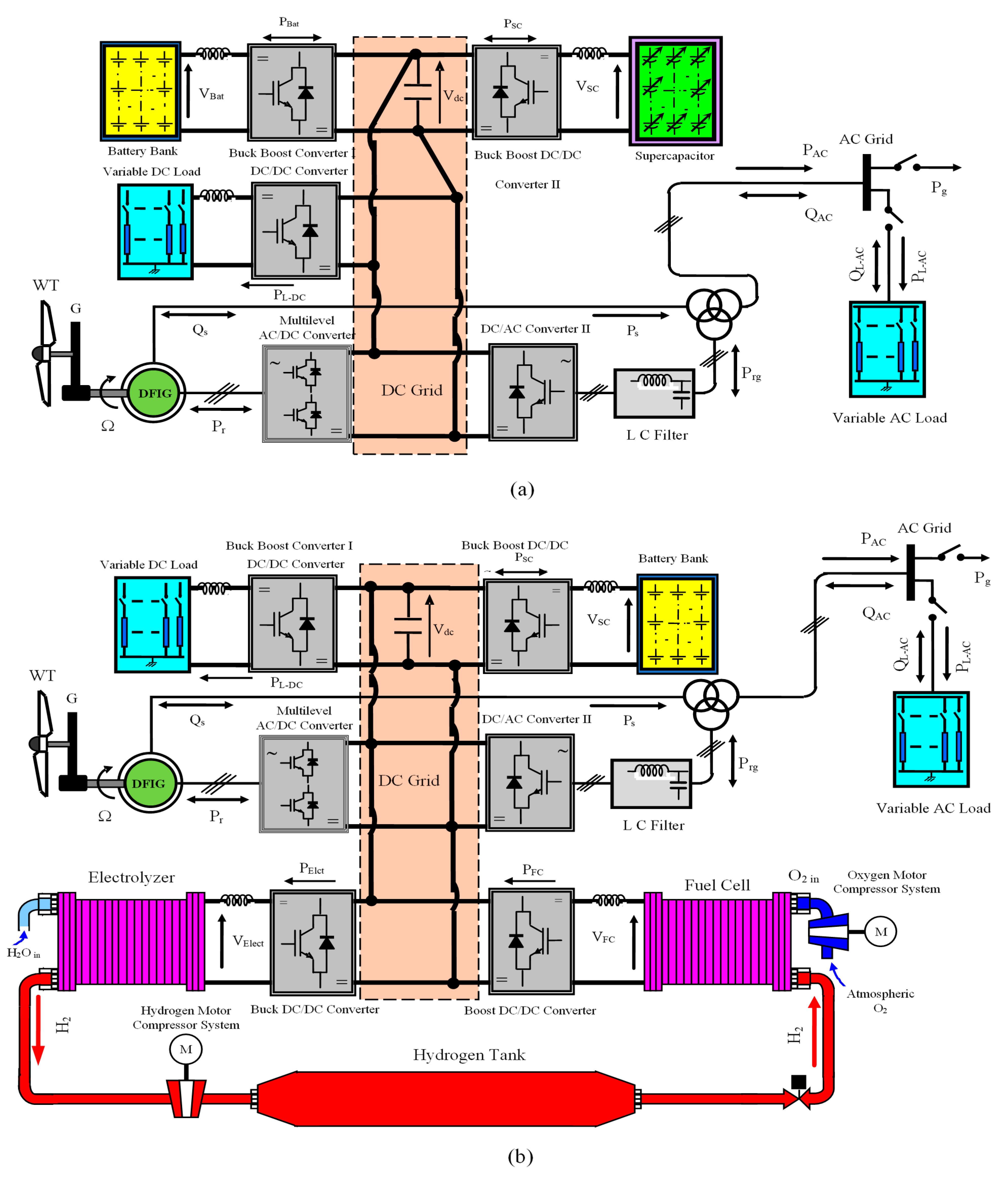
2. Description of the Proposed Micro-grid Hybrid Energy System
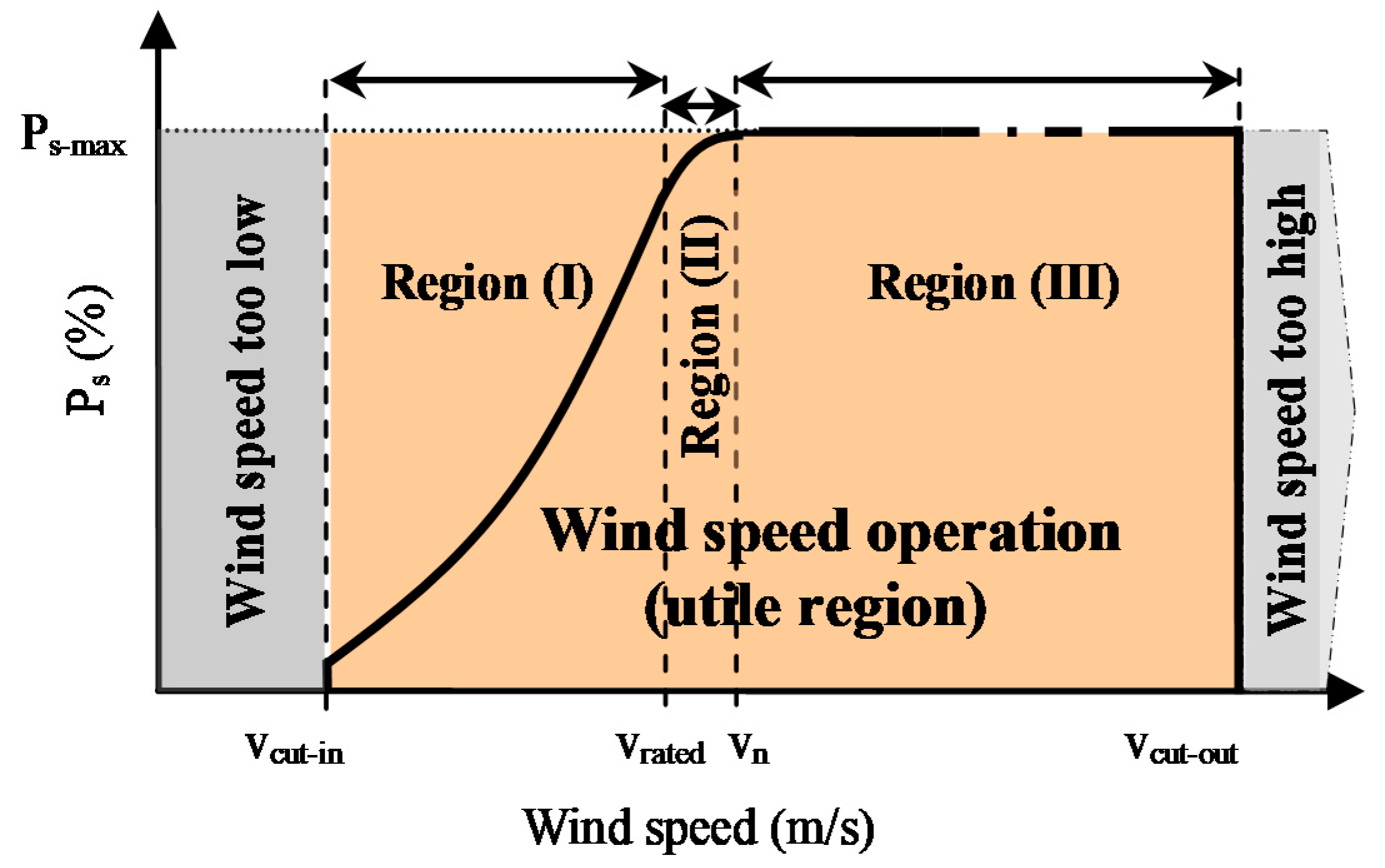
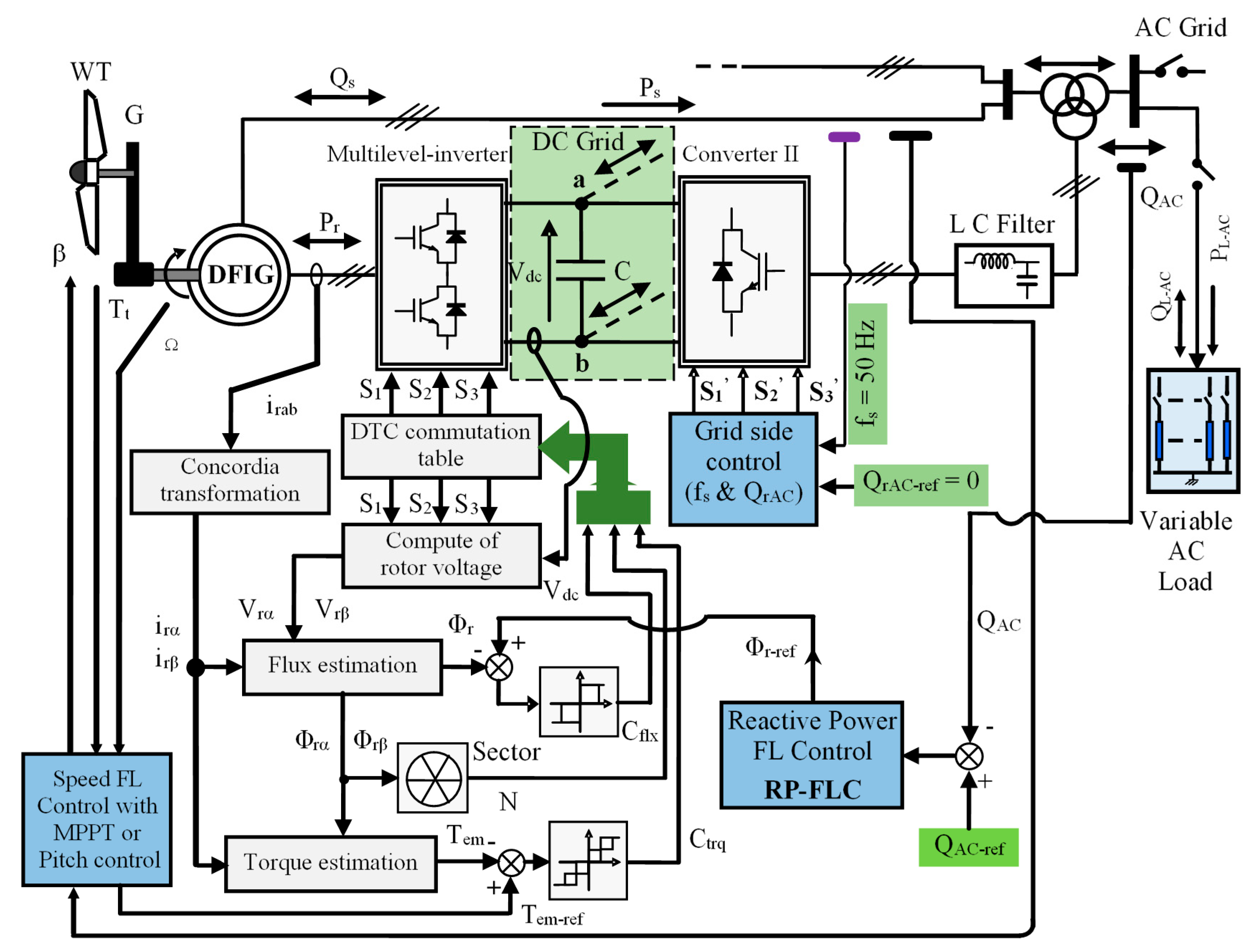
2.1. Model Development for the Wind Energy Conversion
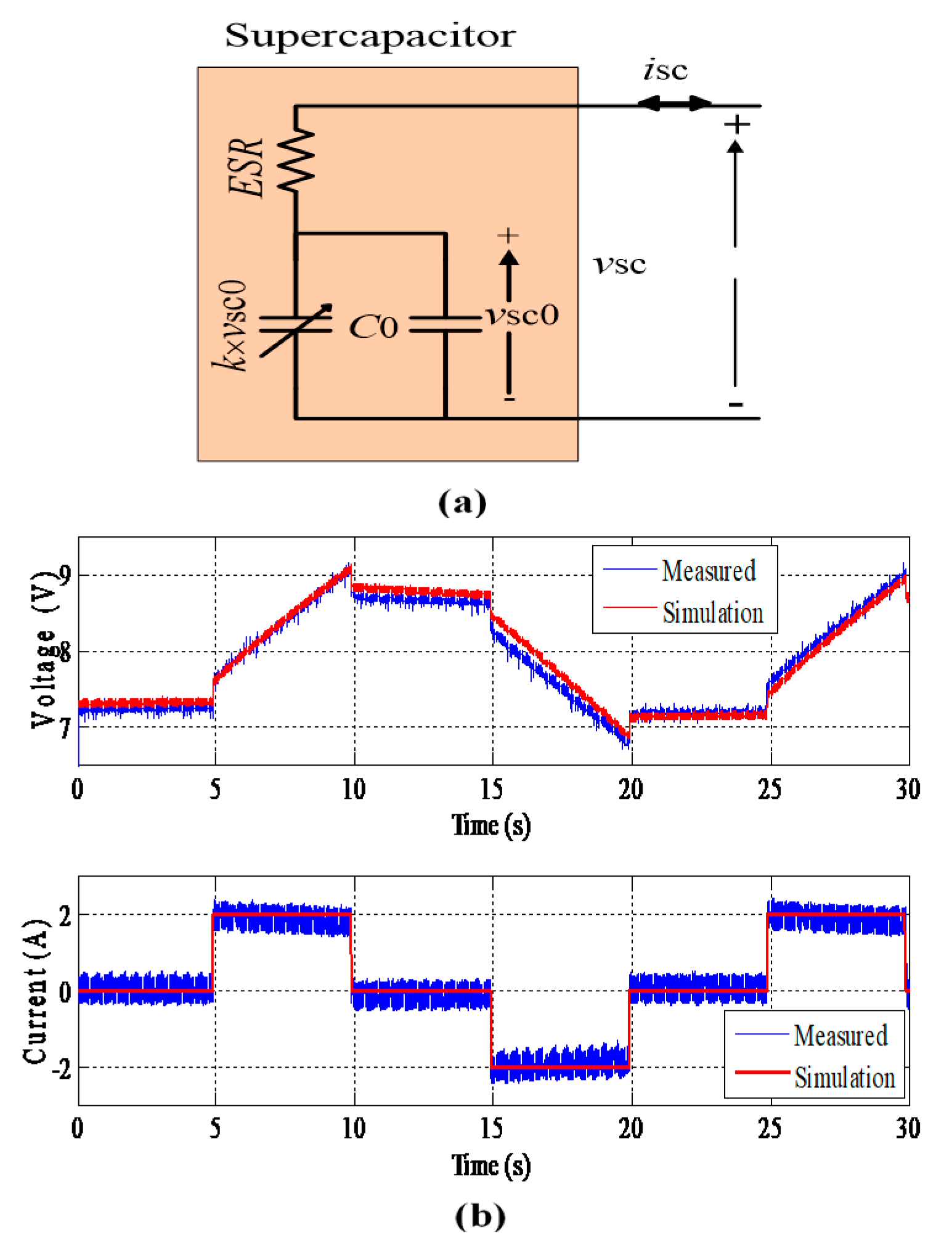
2.2. Model Development for the Supercapacitor
2.3. Model Development for the Battery Bank
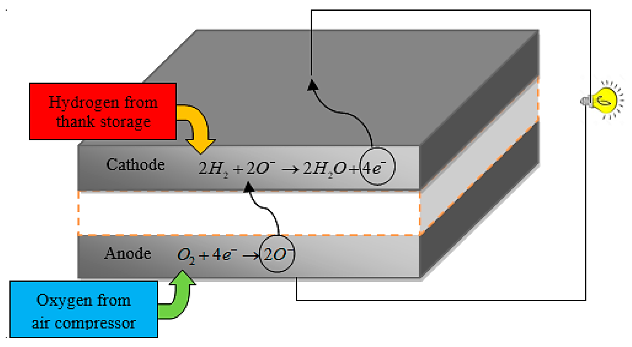
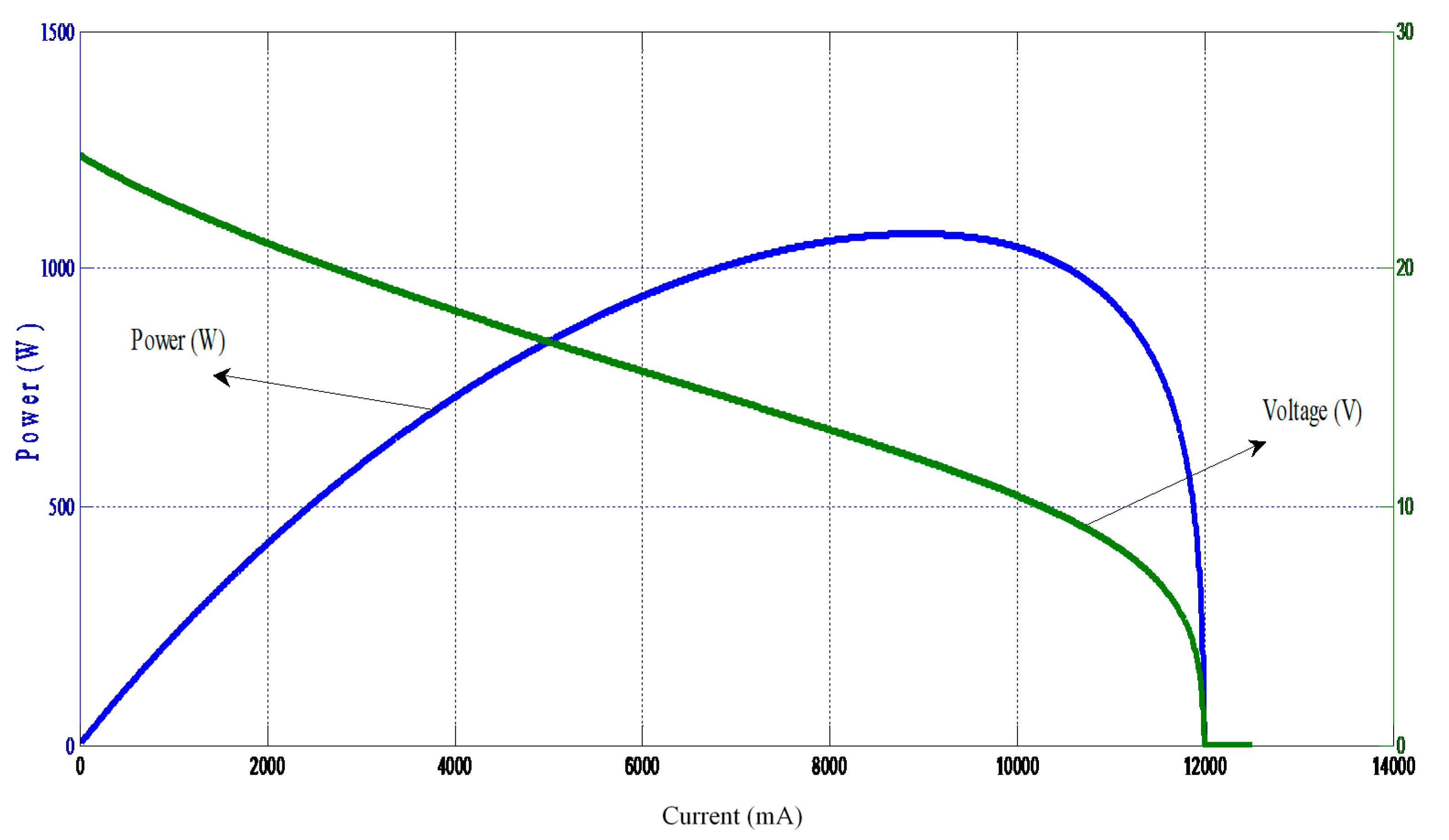
2.4. Model Development for the Fuel Cell
2.5. Model Development for the Electorlyzer
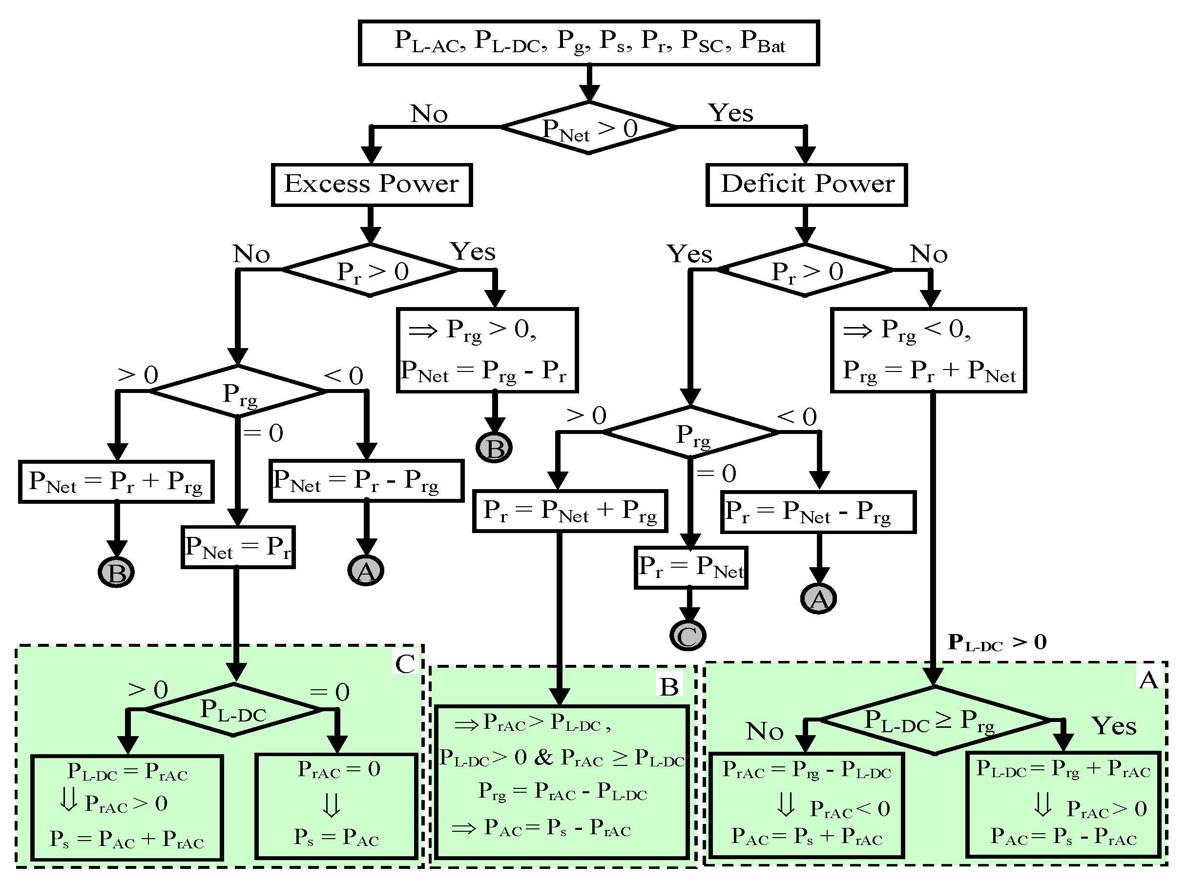
3. Power Management and DC-Grid Voltage Control
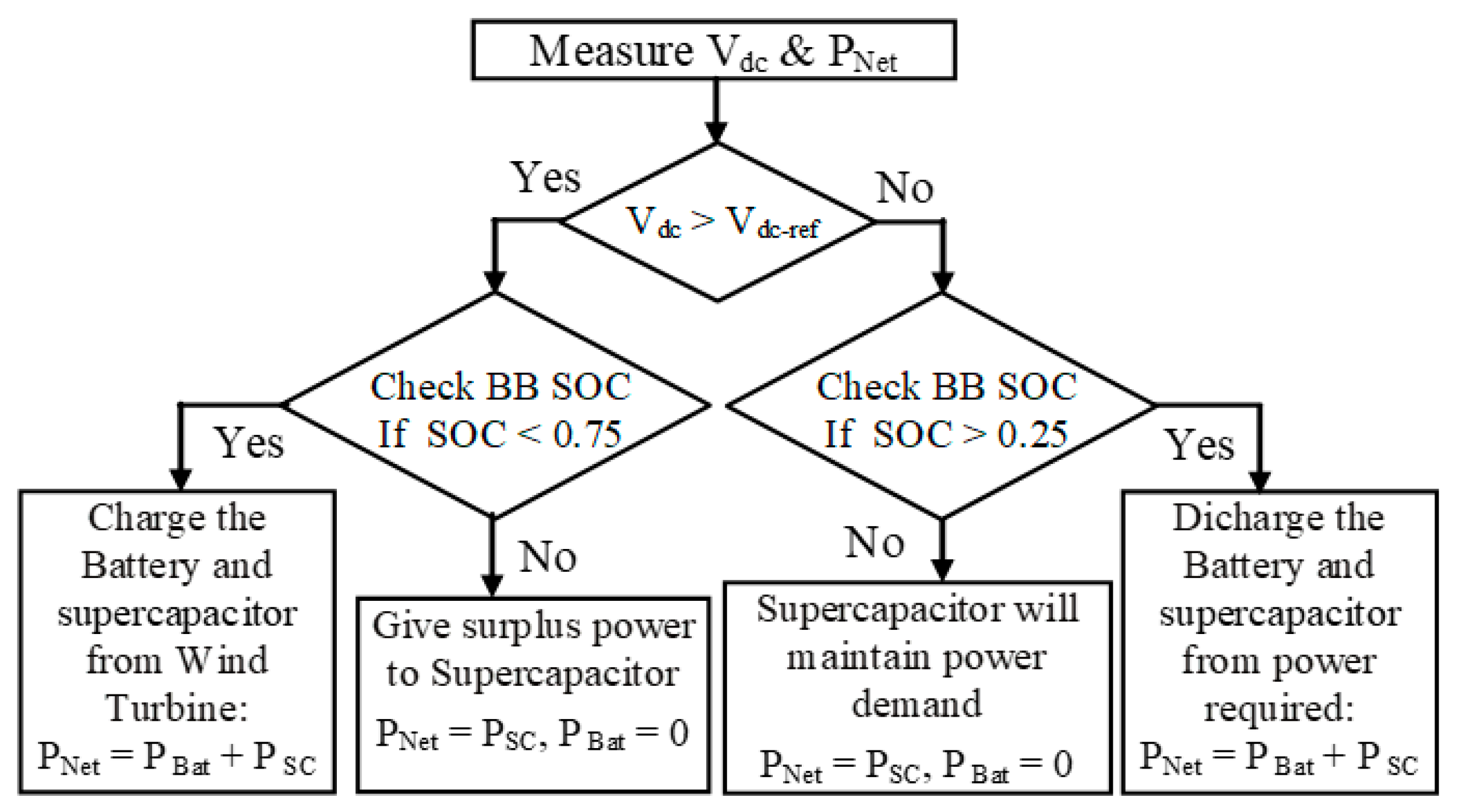
3.1. Hybrid Storage System with BBESS and SCESS
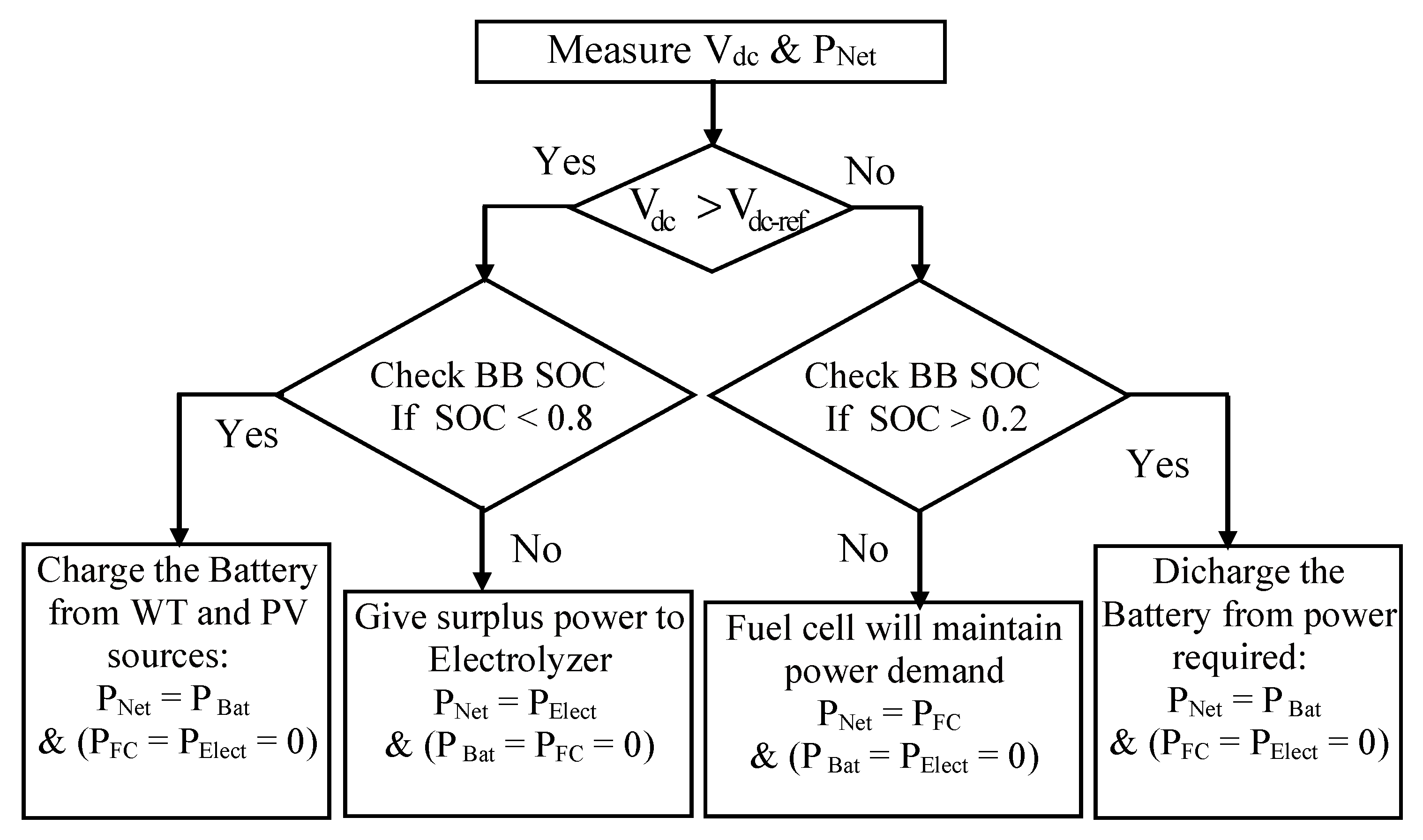
3.2. Hybrid Storage System with Battery Bank and FC Combined with Electrolyzer
4. Results and Discussion
4.1. Results of the Topology1: Hybrid Storage System with BBESS and SCESS
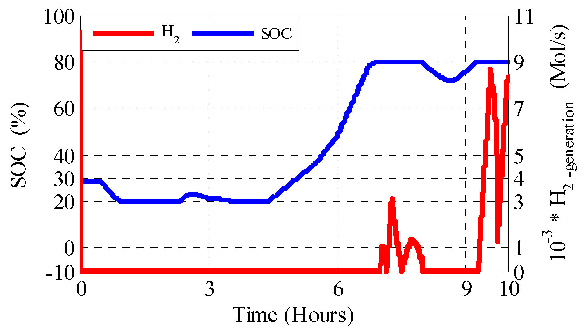
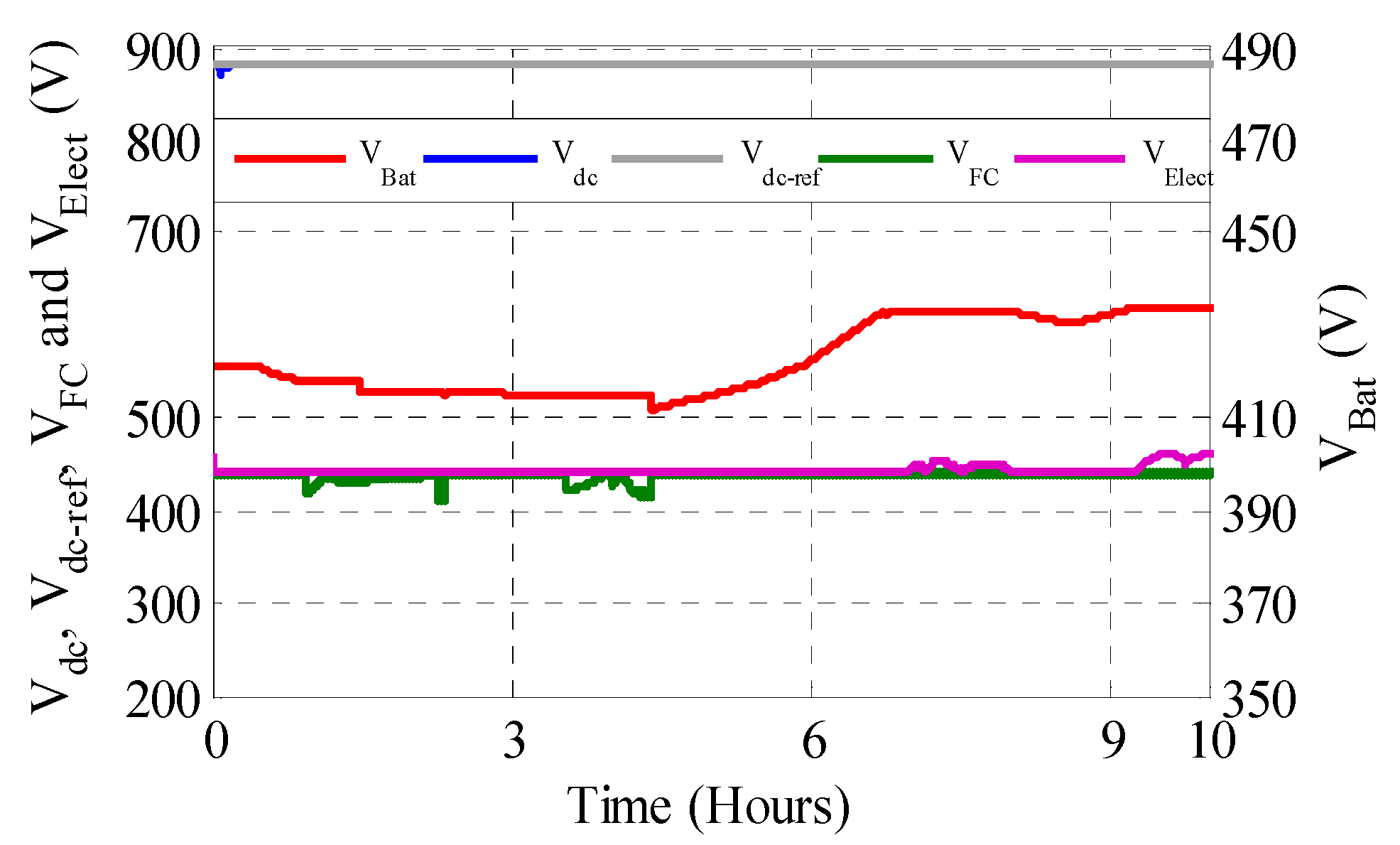
4.2. Results of the Topology2: Hybrid Storage System with Battery Bank and FC Combined with Electrolyzed
- Active and reactive power characteristic;
- Flicker emissions;
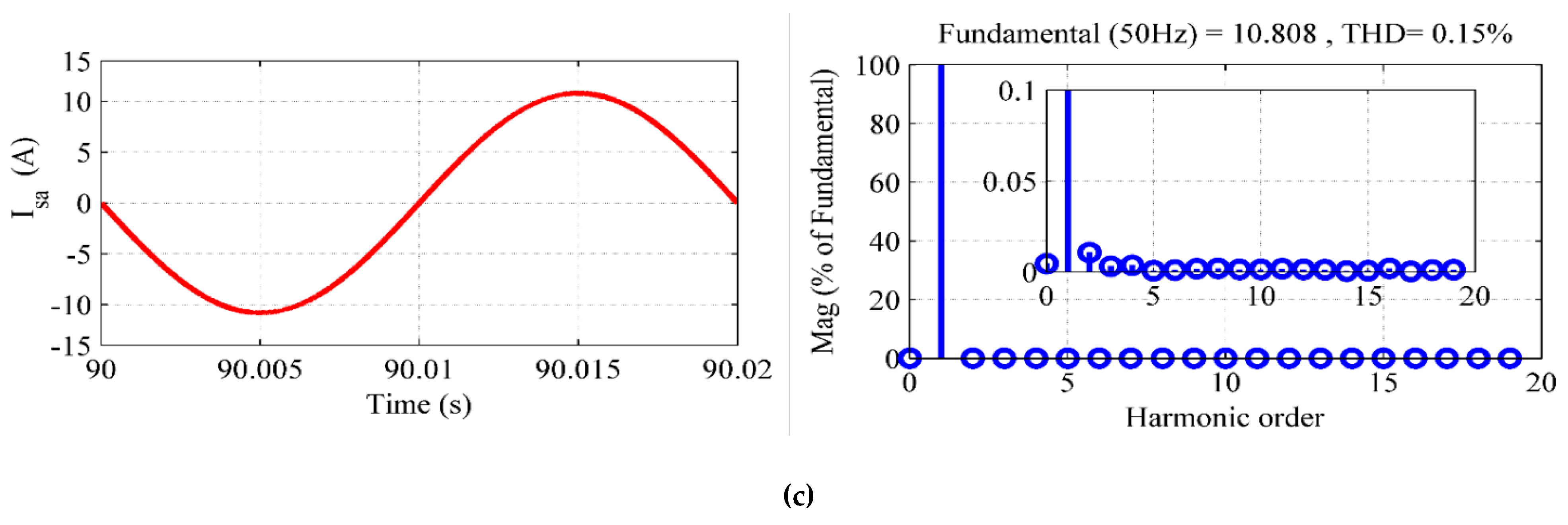
- Current harmonics (THD);
- Active power controls;
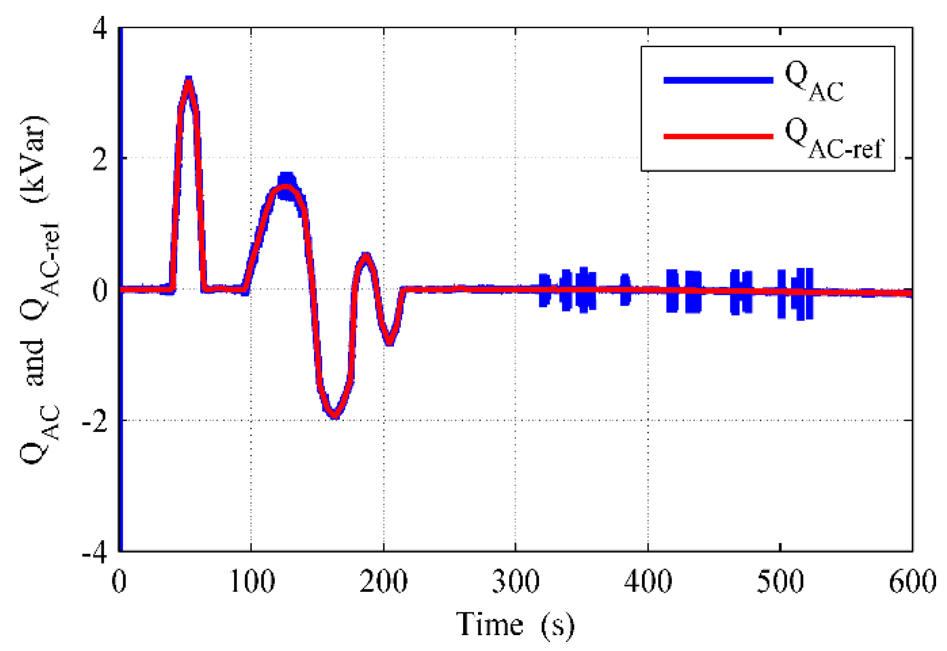
- Reactive power controls.
- (1)
- Active and reactive power characteristic:
- (2)
- Flicker measurement:
- (3)
- Current harmonics:
- (4)
- Active power control:
- (5)
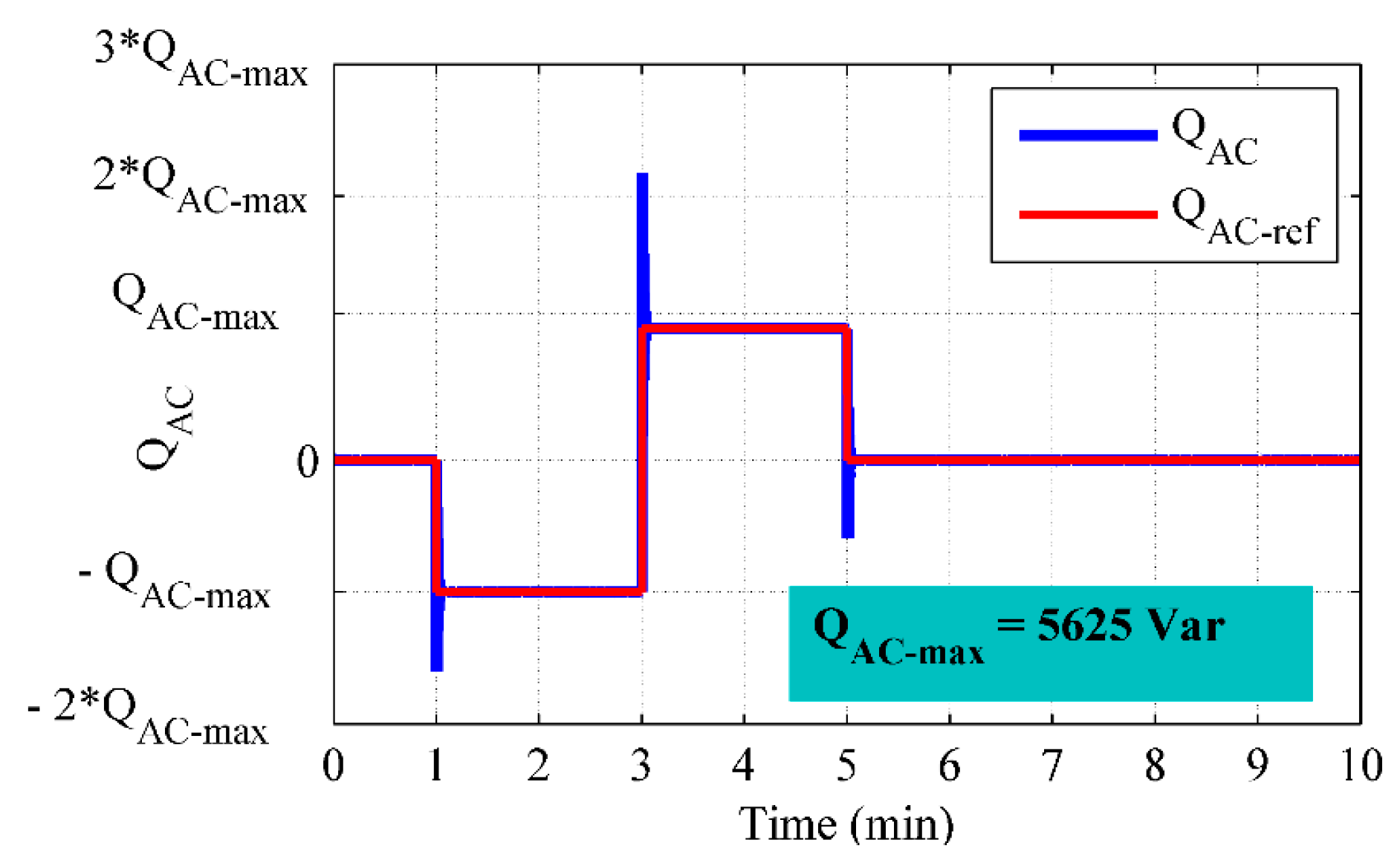
- Reactive power control:
5. Conclusions
Author Contributions
Funding
Institutional Review Board Statement
Informed Consent Statement
Data Availability Statement
Conflicts of Interest
Nomenclature and Abbreviations
| WT | Wind Turbine |
| DFIG | Doubly Fed Induction Generator |
| FC | Fuel Cell |
| BBESS | Battery Bank Energy Storage System |
| Bts | Batteries |
| SCESS | Supercapacitor Energy Storage System |
| Scs | Supercapacitor |
| RES | Renewable Energy Source |
| ESS | Energy Storage System |
| EESS | Electrical Energy Storage System |
| HESS | Hybrid Energy Storage System |
| HEP | Hydrogen Energy Process |
| DC | Direct Current |
| AC | Alternative Current |
| MPPT | Maximum Power Point Tracking |
| BBDC | Buck-Boost Bidirectional Converter |
| DTC | Direct Torque Control |
| FLC | Fuzzy Logic Control |
| DRPC | Direct Reactive Power Control |
| SOC, SOCmax, SOCmin | battery State of Charge with its maximum and a minimum value |
| THD | Total Harmonic Distortion |
| Ch | conditions at the anode or cathode channel. |
| A | anode |
| In | conditions of input/inlet. |
| A | area swept by the rotor blades, m2 |
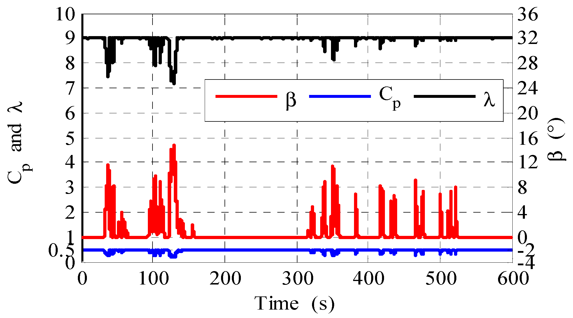
| Cp, Cp-max | power coefficient or the rotor efficiency and its maximum value |
| Tem, Tem-ref | DFIG electromagnetic torque and its reference respectively, N.m |
| Tt | turbine aerodynamic torque, N.m |
| vrated | rated wind speed, tr/min |
| vcut-out, vcut-in | cut out and cut in wind speed (limited) respectively, m/s |
| Ps, Pr | DFIG stator and rotor powers respectively, Watt |
| PL-AC, PL-DC | variable AC and DC load powers respectively, Watt |
| PrAC | power transferred through DC/AC converter II, Watt |
| PSC, PBat, PElect | supercapacitors, batteries banks, and electrolyzer powers respectively, Watt |
| PFC | generated fuel cell power, Watt |
| PAC, Pg | exchanged powers between the proposed system and the AC grid, before and after the local variable AC load, respectively, Watt |
| PNet | DC power exchanged in the DC-grid, Watt |
| Pst | storage power, Watt |
| QAC, QAC-ref | reactive power exchanged between the proposed system and the AC grid with its reference respectively, Var |
| Qs | DFIG stator reactive power, Var |
| QL-AC | local variable AC load reactive power, Var |
| QrAC, QrAC-ref | reactive power transferred through DC/AC converter II and its reference respectively, Var |
| VSc, Vbat, VFC, VElec | supercapacitors, batteries banks, fuel cell, and electrolyzer voltages respectively, Volt |
| Vdc, Vdc-ref | direct voltage in the DC grid and its reference respectively, Volts |
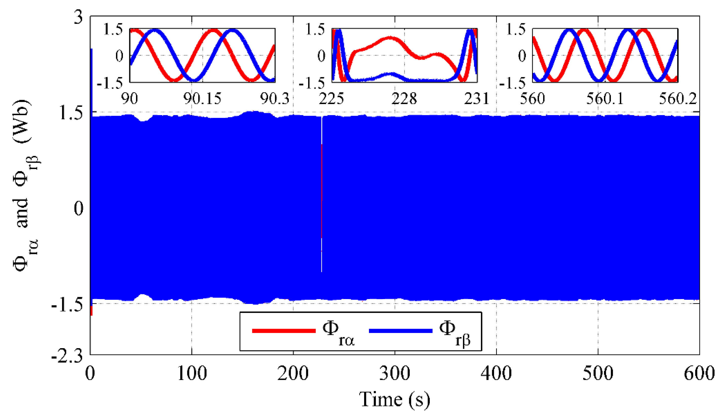
| Irα, Irβ and Vrα, Vrβ | current and voltage components along α and β rotor axes respectively, A and Volts |
| E | electromotive force corresponding to the open circuit battery voltage, Volts |
| Cbat | internal battery capacity, F |
| Rin | internal battery resistance, Ω |
| Ibat, IElect | battery current and electrolyzer current respectively, A |
| ∫i1 dt | charge supplied and drawn by the battery, Ah |
| E0, K, A | unloaded battery voltage, polarization voltage, and exponential zone amplitude respectively, Volts |
| Q, B | battery capacity and exponential zone time inverse constant respectively, Ah and Ah−1 |
| nFC | number of fuel cells in the stack |
| VNernst | Nernst voltage: the thermodynamic potential of the cell representing its reversible voltage, Volts |
| Vcell | cell voltage in the stack, Volts |
| Urev | electrolyzer reversible cell voltage, Volts |
| T | electrolyzer cell temperature, °C |
| Rs, Rr | stator and rotor phase resistances respectively, Ω |
| ls, lr, M | stator and rotor leakage inductances with magnetizing inductance respectively, H |
| Vsd, Vsq, Vrd, Vrq | d-q stator and rotor voltages respectively, Volts |
| Isd, Isq, Ird, Irq | d-q stator and rotor currents respectively, A |
| p | being the pair pole number |
| icell, i0, iL | operating, exchange current of the cell and the limiting current at which the fuel is used up at a rate equal to its maximum supply rate respectively, A |
| Rincell | inherent resistance of the fuel cell, Ω |
| Acell & Bcell | numerical constant coefficients of the fuel cell |
| ∆G | gibbs free enthalpy change, J/kmol |
| R | universal gas constant, Nm/(kmol K) |
| F | Faraday constant, F = 96,439 C/mol |
| Mi | mole flow rate of species i (mol/s) |
| ρ | air density, kg/m3 |
| υ | wind velocity, m/s |
| λ, λopt | tip speed ratio and its optimal value |
| Ωt, Ω, Ωref | turbine rotor speed, DFIG mechanical speed, and its reference respectively, tr/min |
| Φrα, Φrβ & Φr, Φr_ref | rotor flux components along α and β rotor axes and rotor flux and its reference, Wb |
| ϕL-AC, β | local load phase shift and blade pitch angle respectively, ° |
| Pwind | aerodynamic power, Watt |
References
- Alhasnawi, B.; Jasim, B.; Rahman, Z.-A.; Siano, P. A Novel Robust Smart Energy Management and Demand Reduction for Smart Homes Based on Internet of Energy. Sensors 2021, 21, 4756. [Google Scholar] [CrossRef] [PubMed]
- Dorahakia, S.; Dashtia, R.; Reza Shaker, H. Optimal energy management in the smart microgrid considering the elec-trical energy storage system and the demand-side energy efficiency program. J. Energy Storage 2020, 28, 101229. [Google Scholar] [CrossRef]
- Gür, T.M. Review of Electrical Energy Storage Technologies, Materials and Systems: Challenges and Prospects for Large-Scale Grid Storage. Energy Environ. Sci. 2018, 10, 1–154. [Google Scholar] [CrossRef]
- Dinf, H.; Yun, J.; Kim, D.M.; Lee, K.H.; Kim, D. A Home Energy Management System with Renewable Energy and Energy Storage Utilizing Main Grid and Electricity Selling. IEEE Access 2020, 8, 49436–49450. [Google Scholar]
- Anthony, M.; Prasad, V.; Kannadasan, R.; Mekhilef, S.; Alsharif, M.H.; Kim, M.K.; Jahid, A.; Aly, A.A. Autonomous Fuzzy Controller Design for the Utilization of Hybrid PV-Wind Energy Resources in Demand Side Management Environment. Electronics 2021, 10, 1618. [Google Scholar] [CrossRef]
- Ghenai, C.; Bettayeb, M.; Brdjanin, B.; Hamid, A.K. Hybrid solar PV/PEM fuel Cell/Diesel Generator power system for cruise ship: A case study in Stockholm, Sweden. Case Stud. Therm. Eng. 2019, 14, 100497. [Google Scholar] [CrossRef]
- Çolak, M.; Kaya, İ. Multi-criteria evaluation of energy storage technologies based on hesitant fuzzy information: A case study for Turkey. J. Energy Storage 2020, 28, 101211. [Google Scholar] [CrossRef]
- Armghan, A.; Azeem, M.; Armghan, H.; Yang, M.; Alenezi, F.; Hassan, M. Dynamical Operation Based Robust Nonlinear Control of DC Microgrid Considering Renewable Energy Integration. Energies 2021, 14, 3988. [Google Scholar] [CrossRef]
- Amirante, R.; Cassone, E.; Distaso, E.; Tamburrano, P. Overview of recent developments in energy storage: Me-chanical, electrochemical and hydrogen technologies. Energy Convers. Manag. 2017, 132, 372–387. [Google Scholar] [CrossRef]
- Ma, T.; Yang, H.; Lu, L. Development of hybrid battery–supercapacitor energy storage for remote area renewable energy systems. Appl. Energy 2015, 153, 56–62. [Google Scholar] [CrossRef]
- Wang, X.; Yu, D.; Le Blond, S.; Zhao, Z.; Wilson, P. A novel controller of a battery-supercapacitor hybrid energy storage system for domestic applications. Energy Build. 2017, 141, 167–174. [Google Scholar] [CrossRef] [Green Version]
- Zhang, L.; Hu, X.; Wang, Z.; Sun, F.; Dorrell, D.G. A review of supercapacitor modeling, estimation, and appli-cations: A control/management perspective. Renew. Sustain. Energy Rev. 2017, 81, 1868–1878. [Google Scholar]
- Ceraolo, M.; Lutzemberger, G.; Poli, D. State-Of-Charge Evaluation of Supercapacitors. J. Energy Storage 2017, 11, 211–218. [Google Scholar] [CrossRef]
- Salameh, T.; Abdelkareem, M.A.; Olabi, A.G.; Sayed, E.T.; Al-Chaderchi, M.; Rezk, H. Integrated standalone hybrid solar PV, fuel cell and diesel generator power system for battery or supercapacitor storage systems in Khorfakkan, United Arab Emirates. Int. J. Hydrogen Energy 2021, 46, 6014–6027. [Google Scholar] [CrossRef]
- Balsamo, F.; De Falco, P.; Mottola, F.; Pagano, M. Power Flow Approach for Modeling Shipboard Power System in Presence of Energy Storage and Energy Management Systems. IEEE Trans. Energy Convers. 2020, 35, 1944–1953. [Google Scholar] [CrossRef]
- Roy, T.K.; Mahmud, M.A.; Oo, A.M.; Haque, M.E.; Muttaqi, K.M.; Mendis, N. Nonlinear Adaptive Backstepping Controller Design for Islanded DC Microgrids. IEEE Trans. Ind. Appl. 2018, 54, 2857–2873. [Google Scholar] [CrossRef]
- Azeem, O.; Ali, M.; Abbas, G.; Uzair, M.; Qahmash, A.; Algarni, A.; Hussain, M. A Comprehensive Review on Integration Challenges, Optimization Techniques and Control Strategies of Hybrid AC/DC Microgrid. Appl. Sci. 2021, 11, 6242. [Google Scholar] [CrossRef]
- Tamalouzt, S.; Benyahia, N.; Rekioua, T.; Abdessemed, R. Performances analysis of WT-DFIG with PV and fuel cell hybrid power sources system associated with hydrogen storage hybrid energy system. Int. J. Hydrogen Energy 2016, 41, 21006–21021. [Google Scholar] [CrossRef]
- Haddad, A.; Ramadan, M.; Khaled, M.; Ramadan, H.S.; Becherif, M. Triple hybrid system coupling fuel cell with wind turbine and thermal solar system. Int. J. Hydrogen Energy 2019, 45, 11484–11491. [Google Scholar] [CrossRef]
- Kadri, A.; Marzougui, H.; Aouiti, A.; Bacha, F. Energy management and control strategy for a DFIG wind turbine/fuel cell hybrid system with super capacitor storage system. Energy 2019, 192, 116518. [Google Scholar] [CrossRef]
- Li, P.; Guo, T.; Zhou, F.; Yang, J.; Liu, Y. Nonlinear coordinated control of parallel bidirectional power converters in an AC/DC hybrid microgrid. Int. J. Electr. Power Energy Syst. 2020, 122, 106208. [Google Scholar] [CrossRef]
- Xu, Y.; Shen, X. Optimal Control Based Energy Management of Multiple Energy Storage Systems in a Microgrid. IEEE Access 2018, 6, 32925–32934. [Google Scholar] [CrossRef]
- Nami, A.; Liang, J.; Dijkhuizen, F.; Demetriades, G.D. Modular multilevel converters for HVDC applications: Review on converter cells and functionalities. IEEE Trans. Power Electron. 2015, 30, 18–36. [Google Scholar] [CrossRef]
- Prakash, T.S.; Kumar, P.S.; Chandrasena, R.P.S. A Novel IUPQC for Multi-Feeder Systems Using Multilevel Converters with Grid Integration of Hybrid Renewable Energy System. IEEE Access 2020, 8, 44903–44912. [Google Scholar] [CrossRef]
- Arcos-Aviles, D.; Pascual, J.; Guinjoan, F.; Marroyo, L.; García-Gutiérrez, G.; Gordillo-Orquera, R.; Llanos-Proaño, J.; Sanchis, P.; Motoasca, T.E. An Energy Management System Design Using Fuzzy Logic Control: Smoothing the Grid Power Pro-file of a Residential Electro-Thermal Microgrid. IEEE Access 2021, 9, 25172–25188. [Google Scholar] [CrossRef]
- Alharbi, Y.M.; Al Alahmadi, A.A.; Ullah, N.; Abeida, H.; Soliman, M.S.; Khraisat, Y.S. Super Twisting Fractional Or-der Energy Management Control for a Smart University System Integrated DC Micro-Grid. IEEE Access 2020, 8, 128692–128704. [Google Scholar] [CrossRef]
- Kumar, M.; Srivastava, S.C.; Singh, S.N. Control strategies of a DC microgrid for grid connected and islanded operations. IEEE Trans. Smart Grid 2015, 6, 1588–1601. [Google Scholar] [CrossRef]
- Hajebrahimi, H.; Kaviri, S.M.; Eren, S.; Bakhshai, A. A New Energy Management Control Method for Energy Storage Systems in Microgrids. IEEE Trans. Power Electron. 2020, 35, 11612–11624. [Google Scholar] [CrossRef]
- Kakigano, H.; Miura, Y.; Ise, T. Distribution Voltage Control for DC Microgrids Using Fuzzy Control and Gain-Scheduling Technique. IEEE Trans. Power Electron. 2012, 28, 2246–2258. [Google Scholar] [CrossRef]
- Tamalouzt, S.; Idjdarene, K.; Rekioua, T.; Abdessamed, R. Direct Torque Control of Wind Turbine Driven Doubly Fed Induction Generator. Rev. Roum. Sci. Tech.–Electrotechnol. Energy 2016, 61, 244–249. [Google Scholar]
- Tamalouzt, S. Performances of direct reactive power control technique applied to three level-inverter under random behav-ior of wind speed. Rev. Roum. Sci. Tech.–Electrotechnol. Energy 2019, 64, 33–38. [Google Scholar]
- Saha, M.; Saha, P.; Khanra, M. Performance Comparison of Nonlinear State Estimators for State-of-Charge Estimation of Supercapacitor. In Proceedings of the 2021 IEEE Second International Conference on Control, Measurement and Instrumentation (CMI), Kolkata, India, 8–10 January 2021; pp. 105–109. [Google Scholar]
- Kompan, M.E.; Malyshkin, V.G. On the inverse relaxation approach to supercapacitors characterization. J. Power Sources 2020, 484, 229257. [Google Scholar] [CrossRef]
- Al Alahmadi, A.A.; Belkhier, Y.; Ullah, N.; Abeida, H.; Soliman, M.S.; Khraisat, Y.S.H.; Alharbi, Y.M. Hybrid Wind/PV/Battery Energy Management-Based Intelligent Non-Integer Control for Smart DC-Microgrid of Smart University. IEEE Access 2021, 9, 98948–98961. [Google Scholar] [CrossRef]
- Khan, M.S.; Ahmad, I.; Abideen, F.Z.U. Output Voltage Regulation of FC-UC Based Hybrid Electric Vehicle Using Integral Backstepping Control. IEEE Access 2019, 7, 65693–65702. [Google Scholar] [CrossRef]
- Benyahia, N.; Denoun, H.; Zaouia, M.; Tamalouzt, S.; Bouheraoua, M.; Benamrouche, N.; Haddad, S. Characterization and control of supercapacitors bank for stand-alone photovoltaic energy. Energy Procedia 2013, 42, 539–548. [Google Scholar] [CrossRef] [Green Version]
- Aly, M.; Ahmed, E.M.; Rezk, H.; Mohamed, E.A. Marine Predators Algorithm Optimized Reduced Sensor Fuzzy-Logic Based Maximum Power Point Tracking of Fuel Cell-Battery Standalone Applications. IEEE Access 2021, 9, 27987–28000. [Google Scholar] [CrossRef]
- Borji, M.; Atashkari, K.; Nariman-zadeh, N.; Masoumpour, M. Modeling, parametric analysis and optimization of an an-ode-supported planar solid oxide fuel cell. J. Mech. Eng. Sci. 2015, 229, 3125–3140. [Google Scholar] [CrossRef]
- Guney, M.S.; Tepe, Y. Classification and assessment of energy storage systems. Renew. Sustain. Energy Rev. 2017, 75, 1187–1197. [Google Scholar] [CrossRef]
- Buchaniec, S.; Sciazko, A.; Mozdzierz, M.; Brus, G. A Novel Approach to the Optimization of a Solid Oxide Fuel Cell Anode Using Evolutionary Algorithms. IEEE Access 2019, 7, 34361–34372. [Google Scholar] [CrossRef]
- Benyahia, N.; Benamrouche, N.; Rekioua, T. Modeling, design and simulation of fuel cell modules for small marine applications. In Proceedings of the 2012 IEEE XXth International Conference on Electrical Machines, Marseille, France, 2–5 September 2012; pp. 1989–1995. [Google Scholar] [CrossRef]
- Benyahia, N.; Denoun, H.; Zaouia, M.; Rekioua, T.; Benamrouche, N. Power system simulation of the fuel cell and supercapacitor based electric vehicle using an interleaving technique. Int. J. Hydrogen Energy 2015, 40, 15806–15814. [Google Scholar] [CrossRef]
- Malla, S.G.; Bhende, C.N. Voltage control of stand-alone wind and solar energy system. Electr. Power Energy Syst. 2014, 56, 361–373. [Google Scholar] [CrossRef]
- IEC 61400-21. Wind Turbine Generator System—Part 21: Measurement and Assessment of Power Quality Characteristics of Grid Connected Wind Turbines. 2008. Available online: https://webstore.iec.ch/p-preview/info_iec61400-21%7Bed1.0%7Den_d.pdf (accessed on 20 August 2021).
- IEC 61000-4-15. Electromagnetic Compatibility (EMC)—Part 4: Testing and Measurement Techniques—Section 15: Flick-Ermeter—Functional and Design Specification. 1997+A1: 2003. Available online: https://webstore.iec.ch/publication/4173 (accessed on 20 August 2021).
- IEC 61000-4-7. Electromagnetic Compatibility (EMC)—Part 4–7 Testing and Measurement Techniques—General Guide on Harmonics and Interharmonics Measurements and Instrumentation, for Power Supply Systems and Equipment Connected Thereto. 2002+AMD1:2008. Available online: https://webstore.iec.ch/preview/info_iec61000-4-7%7Bed2.0%7Den_d.pdf (accessed on 20 August 2021).
- Pena, R.; Clare, J.C.; Asher, G.M. Doubly fed induction generator uising back-to-back PWM converters and its application to variablespeed wind-energy generation. IEE Proc.-Electric Power Appl. 1996, 143, 380–387. [Google Scholar] [CrossRef]
- Bertola, A.; Lazaroiu, G.C.; Roscia, M.; Zaninelli, D. A Matlab-Simulink flickermeter model for power quality studies. In Proceedings of the 11th International conference on harmonics and quality of power, New York, NY, USA, 12–15 September 2004. [Google Scholar]
- Mohammadi, E.; Fadaeinedjad, R.; Naji, H.R. Flicker emission, voltage fluctuations, and mechanical loads for small-scale stall- and yaw-controlled wind turbines. Energy Convers. Manag. 2018, 165, 567–577. [Google Scholar] [CrossRef]
- Kołek, K.; Firlit, A.; Piątek, K.; Chmielowiec, K. Analysis of the Practical Implementation of Flicker Measurement Coproces-sor for AMI Meters. Energies 2021, 14, 1589. [Google Scholar] [CrossRef]
- Tascikaraoglu, A.; Uzunoglu, M.; Vural, B.; Erdinc, O. Power quality assessment of wind turbines and comparison with conventional legal regulations: A case study in Turkey. Appl. Energy 2011, 88, 1864–1872. [Google Scholar] [CrossRef]
- Emanuel, H.; Schellschmidt, M.; Wachtel, S.; Adloff, S. Power quality measurements of wind energy converters with full-scale converter according to IEC 61400-21. In Proceedings of the 2009 10th International Conference on Electrical Power Quality and Utilisation, Lodz, Poland, 15–17 September 2009; pp. 1–7. [Google Scholar]


| Ref. | Microgrid Elements | Method | Main Contribution | The Novelty of the Proposed Strategy |
|---|---|---|---|---|
| [16] | PV-Diesel Generator-BESS-Loads | Control DC microgrid | Adaptive Backstepping |
|
| [25] | PV-Wind-BBSS-Residence | Energy Management | Two low-complexity FLC | |
| [26] | PV-Wind-BBSS-Load | Energy Management | Super Twisting Fractional Order | |
| [27] | PV-Wind-BBSS-SOFC-Loads | Coordinated control | Two Feed-Back control loops and Feed-Forward control loop | |
| [28] | PV-BBSS-Loads | Energy Management | adaptive droop control | |
| [29] | ELDC+ DC loads (Houses) | Distribution Voltage Control | FLC + Gain scheduling | |
| Proposed strategy | Wind-BBSS-SC-SOFC | Energy management + Wind system Control | DRPC with FLC + Multilevel converter + DC control |
| Cflx | Ctrq | N | |||||||||||
|---|---|---|---|---|---|---|---|---|---|---|---|---|---|
| 1 | 2 | 3 | 4 | 5 | 6 | 7 | 8 | 9 | 10 | 11 | 12 | ||
| +1 | +2 | V21 | V16 | V22 | V17 | V23 | V18 | V24 | V19 | V25 | V20 | V26 | V15 |
| +1 | V21 | V2 | V22 | V3 | V23 | V4 | V24 | V5 | V25 | V6 | V26 | V1 | |
| 0 | Zero vector | ||||||||||||
| −1 | V26 | V1 | V21 | V2 | V22 | V3 | V23 | V4 | V24 | V5 | V25 | V6 | |
| −2 | V26 | V15 | V21 | V16 | V22 | V17 | V23 | V18 | V24 | V19 | V25 | V20 | |
| −1 | +2 | V17 | V23 | V18 | V24 | V19 | V25 | V20 | V26 | V15 | V21 | V16 | V22 |
| +1 | V3 | V23 | V4 | V24 | V5 | V25 | V6 | V26 | V1 | V21 | V2 | V22 | |
| 0 | Zero vector | ||||||||||||
| −1 | V5 | V25 | V6 | V26 | V1 | V21 | V2 | V22 | V3 | V23 | V4 | V24 | |
| −2 | V19 | V25 | V20 | V26 | V15 | V21 | V16 | V22 | V17 | V23 | V18 | V24 | |
| 0 | +2 | V22 | V17 | V23 | V18 | V24 | V19 | V25 | V20 | V26 | V15 | V21 | V16 |
| +1 | V22 | V3 | V23 | V4 | V24 | V5 | V25 | V6 | V26 | V1 | V21 | V2 | |
| 0 | Zero vector | ||||||||||||
| −1 | V25 | V6 | V26 | V1 | V21 | V2 | V22 | V3 | V23 | V4 | V24 | V5 | |
| −2 | V25 | V20 | V26 | V15 | V21 | V16 | V22 | V17 | V23 | V18 | V24 | V19 | |
| Parameter | Value | Parameter | Value |
|---|---|---|---|
| Rated Power (kW) | 7.5 | Ls (H) | 0.093 |
| Frequency (Hz) | 50 | Lr (H) | 0.081 |
| Pole (pairs) | 3 | M (H) | 0.0664 |
| Vdc (V) | 880 | Rt (m) | 3.24 |
| Rs (Ω) | 1.02 | ρ (kg/m3) | 1.1225 |
| Rr (Ω) | 0.8 | G | 5.065 |
| Kind of System | Variable Speed |
|---|---|
| Rated active power | 7.5 kW |
| Rated reactive power | 5.625 kVar |
| Rated rotational speed | 296 Rpm |
| Rated wind speed | 10 m/s |
| Cut-in speed | 4 m/s |
| Cut-out speed | 12 m/s |
| Inertia | 7.5 Kg.m2 |
| Friction coefficient | 0.06 N.m.s/rad |
| Stator voltage | 415 V |
| Rotor voltage | 440 V |
| Rated stator current | 19 A |
| Rated rotor current | 11 A |
| Rated DFIG speed | 970 Rpm |
Publisher’s Note: MDPI stays neutral with regard to jurisdictional claims in published maps and institutional affiliations. |
© 2021 by the authors. Licensee MDPI, Basel, Switzerland. This article is an open access article distributed under the terms and conditions of the Creative Commons Attribution (CC BY) license (https://creativecommons.org/licenses/by/4.0/).
Share and Cite
Sahri, Y.; Belkhier, Y.; Tamalouzt, S.; Ullah, N.; Shaw, R.N.; Chowdhury, M.S.; Techato, K. Energy Management System for Hybrid PV/Wind/Battery/Fuel Cell in Microgrid-Based Hydrogen and Economical Hybrid Battery/Super Capacitor Energy Storage. Energies 2021, 14, 5722. https://doi.org/10.3390/en14185722
Sahri Y, Belkhier Y, Tamalouzt S, Ullah N, Shaw RN, Chowdhury MS, Techato K. Energy Management System for Hybrid PV/Wind/Battery/Fuel Cell in Microgrid-Based Hydrogen and Economical Hybrid Battery/Super Capacitor Energy Storage. Energies. 2021; 14(18):5722. https://doi.org/10.3390/en14185722
Chicago/Turabian StyleSahri, Younes, Youcef Belkhier, Salah Tamalouzt, Nasim Ullah, Rabindra Nath Shaw, Md. Shahariar Chowdhury, and Kuaanan Techato. 2021. "Energy Management System for Hybrid PV/Wind/Battery/Fuel Cell in Microgrid-Based Hydrogen and Economical Hybrid Battery/Super Capacitor Energy Storage" Energies 14, no. 18: 5722. https://doi.org/10.3390/en14185722