1. Introduction
Research into energy-saving conveyor belts has been conducted by scientists, belt manufacturers, and by users of belt conveyors [
1,
2,
3]. The choice of appropriate materials and designs in energy-saving belts has also been an object of interest at Wroclaw University of Science and Technology, where unique research methods and test rigs have been developed [
4,
5,
6]. This research has been performed in cooperation with conveyor belt manufacturers and with the largest operators of such belts, i.e., with surface lignite mines, underground copper ore mines, as well as with hard coal mines. The focus has been placed mainly on steel-cord belts, as belts of this type are typically used on conveyors having greatest lengths and capacities, and such conveyors are operated in lignite mines. The drive mechanisms of such conveyors also allow greatest savings in electricity consumption. As a matter of fact, manufacturers of single-ply textile belts with aramid core and of multi-ply textile belts with polyamide-polyester core have recently started to express interest in the energy-efficiency of such belts as well, and this fact represents a promising further research option [
7].
The need for investigations into lower energy consumption of belt conveyor drive mechanisms is demonstrated not only by successful and tested implementations abroad [
8,
9,
10], but also, and most importantly, by the popularity of belt conveyors in the Polish mining industry. Recent long-haul conveyors incorporate unconventional technical solutions, which result from research works performed into belt conveyor resistances to motion [
11,
12]. In the near future, similar solutions are expected to be introduced in the Polish mining industry. In Polish copper ore mining plants, discussions have intensified on the need to replace series of short belt conveyors with several long steel-cord conveyors. Promising experiments and economic results are also reported by some hard coal mines, where rail transportation has been replaced with long belt conveyors [
13].
An analysis of belt transportation systems in Polish copper ore mines shows the scale of the issue [
14,
15]. Currently, three mines operated by KGHM Polska Miedz S.A. have 185 conveyors (40 in the Lubin mine, 65 in the Rudna mine, and 80 in the Polkowice-Sieroszowice mine) with over 245 km of belts installed. The majority of these belts are textile multi-ply belts. The power of the drive systems installed on the conveyors is 68 MW. The Turow lignite mine operated by PGE Gornictwo i Energetyka Konwencjonalna S.A. uses more than 160 km of conveyor belts having widths from 1400 mm to 2250 mm, 70% of which are steel-cord belts. The Belchatow mine operated by the same company has over 240 km of steel-cord conveyor belts. The power of the drive mechanisms used in this mine and working in the loader─conveyor─stacker (LCS) system is more than 470 MW. Thus, mining companies are interested in lowering the operating costs of belt conveyor transportation, which depend on the costs of electricity consumption and on the operating costs of the conveyor elements, in particular belts, idlers, and drive mechanisms.
Considering the application range of belt conveyors in Polish lignite mines and the number of steel-cord belts installed on these conveyors, electricity savings from the drive mechanisms seem vast. The scale of such savings is currently being analyzed at the Belchatow mine [
16,
17].
This article presents the results of comparative research into the energy-efficiency of steel-cord conveyor belts. It describes the impact of replacing traditionally used belts with energy-efficient belts on the lowering of the power demand from belt conveyors. This impact is shown using the example of a conveyor operated in the Belchatow mine. The tests were performed with steel-cord belts as test objects, as this type of belts dominates in lignite mines. However, many other types of conveyor belts exist, which are commonly used in other branches of industry [
18,
19].
2. Materials and Methods
2.1. Belt Indentation Rolling Resistance
When a viscoelastic belt rolls on idler sets, a part of its energy is transformed (dissipated). The increase of the force in the belt required to overcome the energy losses on an individual idler set is defined as the belt indentation rolling resistance, or the rolling resistance of the belt on idlers. In a model-based approach, it is the resistance that accompanies the movement of a rigid cylinder (idler) rolling on a deformable surface (belt) [
20].
The identification of the belt indentation rolling resistance was attempted with the use of theoretical data [
21]. Furthermore, complicated experimental tests were performed on a conveyor and their results served to define coefficients, which additionally allowed for how rolling resistances are influenced by the belt trough, the belt design, and the force in the belt, as well as by the degree to which the belt is loaded with the transported material [
22,
23].
In publications [
24,
25], rheological models were used to derive formulas, which were for the first time based on physical parameters, including the viscoelastic properties of the belt, in such a way that they can be applied to any type of belt. Viscoelastic properties describe the behavior of elastomers at a defined load, providing a nonlinear relationship between the load and the deformation, as well as between the load and the deformation velocity. Experimental tests [
26] allow accounting for the influence of certain conveyor operating parameters, i.e., belt velocity and ambient temperature, on belt rolling resistances, which is important, as conveyor belts work in extremely different climate conditions. The previous publications are based on both theoretical models and laboratory tests. The missing element was for these results to be confirmed in actual conveyor operating conditions [
27]. Extensive research on how the properties of belts and their bottom covers influence belt indentation rolling resistances was presented in [
28]. The tests included materials used in the bottom covers of conveyor belts made of various rubber types and with various additions of soot. They were performed in a laboratory, on a dedicated test rig in a climatic chamber, at uniform load, velocity, idler diameter, and cover thickness. The lowering of ambient temperature has been observed to have a negative influence on the indentation rolling resistances of the investigated belts.
An increase of belt indentation rolling resistances due to increasing belt loads is an important design factor in the case of long belt conveyors. Publication [
29] describes a dedicated test rig for measuring belt indentation rolling resistances. The measurements can be performed based on belt load, belt velocity, idler diameter, ambient temperature, and type of rubber mixtures used in belt covers.
The above-discussed publications have become a basis for introducing national standards describing methods for measuring belt indentation rolling resistances [
30,
31,
32]. In both cases, the rolling resistances were identified with the use of belts closed in loops. In order to reduce the test costs related to the significant length of the belt test sections, which need to be additionally spliced in loops, a small-scale rolling resistance test method has been proposed [
33].
The literature also proposed variable velocity adjustment as a means for improving the operating effectiveness of belt conveyors [
34]. A reduction of the electric energy consumption in transportation systems comprising belt conveyors can also be achieved by an optimal use of the operating schedule of such systems [
35,
36,
37,
38,
39,
40,
41].
The phenomena occurring in the belt during the implementation of the propulsion process are described in the measurement methodology of other researchers [
42], and make it possible to determine the energy consumption of the implemented processes.
Results of tests into the energy-efficiency of belt conveyor transportation systems [
43,
44,
45] demonstrate that the energy consumption of their drive mechanisms can be limited by lowering the main resistances in the conveyor. Main resistances are related to the movement of the belt on the idler sets and are a sum of components depending on belt properties. They include belt indentation rolling resistance and belt flexure resistances. The remaining components of main resistances are represented by resistances independent of the belt properties. They include idler rotational resistances, material flexure resistance and sliding resistance of the belt on idlers. An analysis of belt movement on idler sets indicates that belt indentation rolling resistance and belt flexure resistance are significantly influenced by the properties of the conveyor belt, which account for approximately 60% of the main resistances in the conveyor. A vast majority of the main resistances (approximately 80%) is in turn represented by belt indentation rolling resistances. They can be minimized with adequately selected bottom covers of the conveyor belt. Belt indentation rolling resistance most significantly affects the electricity consumption level of the belt conveyor. Therefore, with appropriate bottom covers, belts can be designed to have reduced rolling resistances and thus the electric energy consumption of conveyor drive mechanisms can also be reduced. As a result, such a conveyor belt becomes an energy-saving belt.
This article presents a dedicated test rig and a practical method for conveyor belt tests with respect to identifying unit indentation rolling resistances. Such phenomena as contamination on the belt, belt wear and tear, abrasion of the covers, or belt cuts, which all occur frequently on the belt conveyors operated in a mine, are not observed during laboratory tests and therefore their influence was not accounted for in the measurement results.
2.2. Test Rig
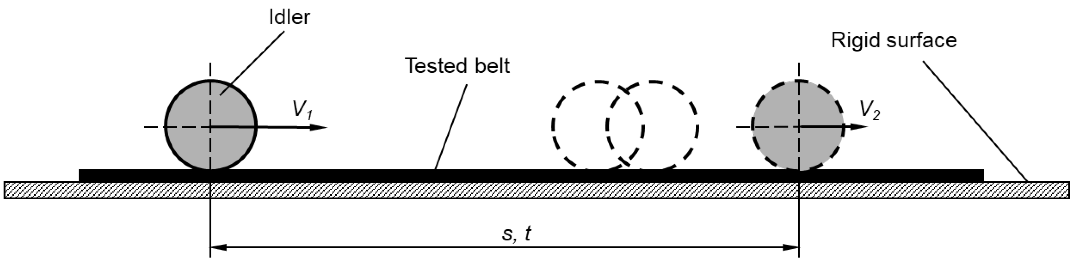
The simplest and also the most accurate method for testing belt indentation rolling resistances consists in performing measurements according to the schematic diagram of
Figure 1.
The principle behind this measurement is as follows. A conveyor belt having a width
B is placed on a rigid and even surface, with the bottom cover facing upwards. An appropriate idler having a mass
m and a moment of inertia
Ir, normally engaged with such a belt on an actual conveyor, is rolled on the belt with a velocity
V1. Due to the rolling resistances, the idler rolls on the belt with a negative acceleration, losing its velocity and reaching a velocity value
V2. If the time
t required by the idler to travel a distance
s is measured, the result can serve to calculate the negative acceleration (the deceleration) of the idler, and subsequently, by following relationship (1), to find the unit indentation rolling resistance
We:
Symbols used in Equation (1) represent:
We—unit indentation rolling resistance, N/m (the contact zone between the idler and the belt is 1 m);
m—mass of the idler, kg;
Ir—moment of inertia of the idler, kg·m2;
r—radius of the idler, m;
a—deceleration, m/s2.
However, the above-described method has some limitations, which prevent its practical usage. These include the following points:
The weight of the idler is relatively small compared with the mass of the belt and the carried material. Loading a single idler with an additional force required to obtain a desired pressure is practically impossible. The idler mass cannot be simply increased, as this would entail increasing its diameter and the moment of inertia. In effect, the idler parameters would be significantly modified in comparison to typical idlers used on an actual conveyor.
The initial velocity V1 of the idler rolling on the belt should be approximately 3.5–6.5 m/s, so that it adequately represents the actual velocities of steel-cord belts operated on conveyors in surface lignite mines. The idler should roll on the belt along a distance of more than ten meters, so that the difference between V1 and V2 is significant and allows the required measurement accuracy.
The measurement can also be performed until V2 reaches a velocity equal to 0. In such a case, the belt specimen needed in the test should be more than 20 m in length. The belt manufacturing technology, the dimensions of vulcanization presses and the price of materials cause the cost of such a specimen to be very high and in fact prohibitive to potential clients. In the case when V2 = 0, the measure in the test is the distance s traveled by the idler until it stops. An idler rolling on a belt with reduced rolling resistance will travel a longer distance in comparison to a belt having higher rolling resistance values.
Considering the above, ensuring that an idler can travel along a belt on a straight path is practically impossible. Importantly, each deviation from the rectilinear movement path generates additional resistances and consequently could result in the idler leaving the belt. Taking into account the above limitations, a decision was made that the tests would be performed with the use of two idlers positioned in a dedicated metal frame. Owing to such a solution, the idlers can travel along the belt in a straight line. The carriage frame can be additionally loaded in order to exert a desired pressure force of the idlers on the belt. A limitation of the frame-loading option is that in such case calculations of the indentation rolling resistances must include the rotational resistances of idler bearings. These resistances can be measured, however. In order to minimize the dimensions of the test specimens, a decision was made that the idlers would roll on a belt placed on a rigid and slightly inclined surface.
Design Concept
The following assumptions dictated the design and preparation of the test rig for testing the conveyor belt indentation rolling resistance:
The width of the tested belt specimen should be 0.5 m.
The length of the test specimen should be approximately 7.5 m.
The minimum length of the measurement section should be 5 m.
The tested belt should be supported along its entire length and width by a flat and rigid surface.
The tests should be performed with the use of two idlers secured in a rigid frame, which can be additionally loaded. It was also assumed that the outer diameter of the idler should correspond to the diameter of idlers used in the transportation of overburden in lignite mines and should be 190 mm, while the length of the idler coat should be 630 mm. The idlers should have a defined:
- -
Moment of inertia Ir, kg·m2;
- -
Rotational resistance Wk, N.
The idler frame should be ready to accommodate weights in order to allow the idlers to exert a desired pressure against the belt.
An initial velocity should be given to the idler frame with the use of an inclined plane having an inclination angle of approximately 65°. The length of this plane should enable such a carriage to obtain a maximum velocity V1 = 5 m/s with an option to adjust a lower velocity.
In order to reduce the distance traveled by the carriage on the belt, its measurement section should be positioned at an ascending angle of approximately 5°.
The test rig should be equipped with adjustable clamps allowing the proper positioning of both the raceway and the inclined plane, so as to ensure that the carriage travels in a straight line along its entire path on the tested belt.
The required weight of the loading carriage to be rolled on the belt installed in the test rig was calculated based on an average annual load on three-idler sets, which work with a conveyor belt of 1800 mm in width, have a trough angle of 45°, and are spaced at 1.2 m. The calculations were performed with the following parameters:
- -
The nominal cross-sectional area of the transported material on the three-idler set is 0.425 m2,
- -
The bulk density of the transported overburden is 1600 kg/m2,
- -
The average annual load on the conveyor is equal to 40% of the belt nominal load, based on data provided in [
46],
- -
The belt width on the test rig is 0.5 m,
- -
The number of idlers on the loading carriage is 2.
The weight of the loaded carriage, as calculated based on the above data, should be 234 kg.
The travel time t of the carriage along a defined distance s should be measured with the use of tachometer probes, with an accuracy of up to 0.001 s. The tachometers should be secured in dedicated stands fixed to the ground in such a way that they are isolated from the vibration of the test rig. In order to increase the measurement accuracy, it is recommended to use three such tachometer probes.
The belt ends should be secured in clamps that allow the belt to be tensioned.
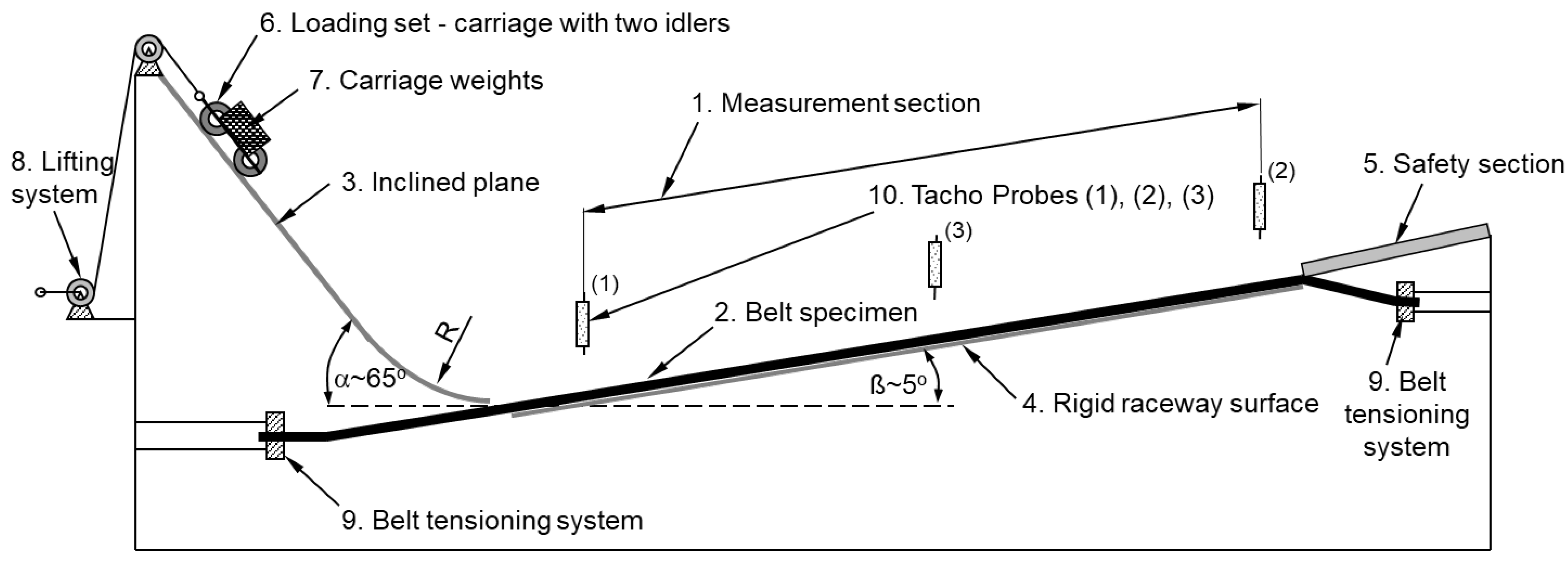
Figure 2 schematically shows a test rig according to the assumptions described in points 1–12.
The symbols shown in
Figure 2 are as follows:
1—measurement section;
2—belt specimen;
3—inclined plane used to accelerate the carriage with two idlers;
4—rigid raceway surface;
5—section used to decelerate and stop the idler set;
6—loading set—carriage with two idlers;
7—carriage weights;
8—system for lifting the carriage;
9—belt tensioning system;
10—tachometer probes Tacho 1, Tacho 2 and Tacho 3.
- 13
The belt unit indentation rolling resistance
We on the test rig according to the schematic representation in
Figure 2 should be calculated following Equation (2). A parameter
Wp present in Equation (2) is related to the movement in height, as the carriage rolls on the belt arranged at an angle
β with respect to the flat surface. This parameter is described by Equation (3):
Symbols used in Equations (2) and (3) represent:
We—belt unit indentation rolling resistance, N/m;
Wk—sum of the dynamic rotational resistances of the two idlers, N;
Wp—carriage lift resistance, N;
m—mass of the carriage, kg;
a—deceleration, m/s2;
Ir—moment of inertia of the idler, kg⋅m2;
r—radius of the idler, m;
g—acceleration of gravity, m/s2;
β—angle of the measurement section of the inclined plane;
B—belt specimen width.
Figure 3a shows the test rig for identifying belt indentation rolling resistances designed and constructed according to the recommendations listed in points 1–13.
Figure 3b, on the other hand, shows the loading set comprising two idlers secured in a metal frame loaded with additional weights (the loading carriage).
2.3. Test Object
The tests covered two conveyor belts used on conveyors operated in Polish surface lignite mines and three energy-saving belts with reduced rolling resistances. They are steel-cord belts type ST 3150 (cord diameter approximately 7.4 mm) having a tensile strength of 3150 kN/m. The test specimens were cut from conveyor belts 2250 mm in width (type B-2250). The test specimens are designated as follows:
1-ST, standard belt commonly used in Polish lignite mines.
1-ST-R1, standard belt after first refurbishment (regenerated).
2-EO, energy-saving belt with a textile breaker in the top and bottom covers located 2 mm from the steel cords.
3-EO, energy-saving belt with a textile breaker in the top and bottom covers located 2 mm from the steel cords.
4-EO, another energy-saving belt with a breaker formed of textile cords in the top and bottom covers located 2 mm from the steel cords.
The belt specimens had the following dimensions: length—7500 mm, width—500 mm, thickness—29.5 mm. The thicknesses of the bottom covers were identical for all belts and were approximately 8 mm. Similarly, the thicknesses of the top covers and the cores were identical for all belts and were approximately 14 mm.
Table 1 lists the following physical and mechanical parameters of the rubber covers (the top and the bottom covers) for the above belts: tensile strength, elongation at break, rubber abrasiveness and hardness.
The belts are types commonly used in Polish lignite mines for transporting overburden to the waste heap and coal to the power plant. Adding reinforcement in the bottom cover improves the rolling parameters of the belt on the idlers (reduced indentation of the idler is observed). On the other hand, adding a textile reinforcement in the top cover improves the resistance of the belt to failures in normal operation, such as punctures, longitudinal cuts, and tears.
2.4. Test Method
The measurement was performed as follows. The belt specimen 500 mm in width and 7500 mm in length is secured in clamps and tensioned, ensuring its stability. The belt specimen is positioned on a rigid, metal surface, with the bottom cover facing upwards. The loading carriage is lifted on an inclined plane to an appropriate height, so that it can travel with a set velocity
V1 in the first velocity measurement point in which velocity is measured with the use of the tachometer probe. After the release system is triggered, the loading set with two idlers rolls on the bottom cover of the belt, and three tachometer probes record the time
t needed by the carriage to move along the belt. Prior to the measurement, the specimen was conditioned at an appropriate temperature. The measurements were performed in temperatures both above and below zero degrees Celsius. The temperature of the belt was measured at several locations along its length. The measurement was performed in the conditioning temperature. Nine measurement points were recorded.
Figure 4 shows an illustrative record of the carriage travel time.
The measurement results served to plot a graph of the distance traveled by the carriage in a function of time
s =
f(
t). The results were approximated with Equation (4):
where:
a—carriage deceleration in uniformly retarded motion, m/s2;
t—travel time of the carriage on the belt, s;
vo—carriage initial velocity, m/s;
so—free term.
The value of deceleration a found from Equation (4) was used to calculate belt unit indentation rolling resistance We in accordance with Equation (2).
2.5. Research Scope
The laboratory tests included the identification of unit indentation rolling resistances for 5 steel-cord conveyor belts. The tests were performed with the use of two standard load-carrying idlers working on a conveyor with an 1800 mm wide belt (type B-1800). The idlers had the following parameters:
Diameter D = 190 mm;
Coat length l = 630 mm;
Moment of inertia Ir = 0.173 kg·m2;
Rotational resistance of a single idler Wk = 4.38 N;
The belt was loaded with unit forces 2.3 kN/m, which corresponded to the weight of the loading set. The calculations of the required carriage weight on the test rig were performed on the basis of the guidelines presented in point 10 of
Section 2.2,
Initial carriage velocity approximately 3.5 m/s;
Measurement section length 5.20 m;
The test temperature corresponded to the conditioning temperature.
Belt indentation rolling resistances depend on the ambient temperature, and therefore, in order to identify these relationships, the tests were performed at positive temperatures of 23.0 ± 2.0 °C and 7.5 ± 2.0 °C and at a negative temperature of –9.0 ± 2.0 °C. The temperature was measured on the bottom cover of the belt.
The scope of research into the indentation rolling resistances of standard and energy-saving belts includes a comparison of:
the influence of bottom cover parameters on indentation rolling resistances;
the influence of bottom cover design on indentation rolling resistances;
the influence of bottom cover refurbishment on indentation rolling resistances.
The tests were performed for one specimen of each belt type, and the carriage traveled along the belt in ten repetitions. The obtained indentation rolling resistance values were compared with the results obtained for the standard 1-ST belt.
3. Results
Table 2 and
Table 3 show, respectively, values representing mean carriage travel times on belts at the positive temperatures of 23.0 ± 2.0 °C and 7.5 ± 2.0 °C.
Table 4, on the other hand, shows values representing mean carriage travel times on belts at the negative temperature of −9.0 ± 2.0 °C. The tables contain mean carriage travel times
t along a distance
s on the belt, as recorded by the three tachometer probes. In the first research stage, the carriage travel times were measured at the beginning and at the end of the measurement section with the use of two tachometer probes (Tacho 1 and Tacho 2). However, because of the nonlinear character of the phenomena occurring in the belt as the idlers roll on it, an additional third probe (Tacho 3) was introduced in the middle of the belt length. As a result, nine measurement points were defined, which allowed Equation (4) to be fitted with more precision.
The data provided in
Table 2,
Table 3 and
Table 4 were used to calculate the deceleration of the idler set and subsequently to calculate unit indentation rolling resistances.
Table 5 contains the values of the idler set deceleration for each investigated temperature, calculated from Equation (4). Subsequently, unit belt indentation rolling resistance values were calculated from Equation (2).
Based on the data provided in
Table 5,
Table 6 was compiled; it contains the indentation rolling resistance test results for different temperatures and for unit loads of 2.3 kN/m. The unit loads correspond to the mean annual loads on belt conveyors in Polish surface lignite mines in Belchatow, Turow, Konin, and Adamow. In other words, they correspond to a situation in which the conveyors are filled with material at 40% capacity, as an average per year. The change in unit rolling resistance is provided in relation to belt 1-ST, which is a standard belt, typically used in the above-mentioned mines. The sign “-” indicates that the belt is characterized by lower indentation rolling resistances in comparison to the standard belt.
In comparison to the standard belt, all the tested energy-saving belts show lower rolling resistance values. The energy-saving belts designated with symbols 2-EO and 3-EO have similar mean rolling resistance values at almost 33 N/mm. They are lower by approximately (8.5 ÷ 8.7)% from the value obtained for the standard belt, which was 35.9 kN/m. In comparison to the standard belt, the energy-saving belt 4-EO has an indentation rolling resistance lower by approximately 18.5%. On the other hand, the 1-ST-R1 belt shows indentation rolling resistance higher by 7.0% in comparison to the 1-ST belt. This value is due to the fact that the belt was subjected first to a refurbishment. The costs of new belts incurred by the mines cause the refurbishment of used belts to be profitable. The refurbishment process consists in the removal of damaged covers from the belt and in their replacement with new vulcanized covers made of adequate rubber compound. The refurbishment process also consists in the replacement of damaged cords in the belt core [
47]. Out of the total number of steel-cord belts used at the Belchatow mine, almost 40% are refurbished [
48].
The tests indicated that it is possible to use steel-cord belts with indentation rolling resistances reduced by 8.5% in comparison to standard belts. The test results for the 4-EO belt suggest a potential to reduce these resistances even further.
In comparison to the 3-EO belt, the 4-EO belt is different in the type and design of the reinforcement plies used in the covers, which may be of significance for the obtained belt indentation rolling resistance values.
The application scale of refurbished belts indicates that the refurbishment should be performed with the use of improved materials allowing lower indentation rolling resistances.
4. Discussion
In order to demonstrate the practical advantages resulting from the use of energy-saving belts, this article also included calculations of the power demand of a conveyor drive mechanism, as measured on a belt conveyor operated at the Belchatow mine. The calculations and the analyses were performed for a standard conveyor transporting overburden. The calculations allowed for the dynamic parameters of belt covers that were identified in separate research works. The calculations were performed with a professional QNK-TT software application, which employs an algorithm for calculating conveyor resistances to motion [
49]. The technical data used in the calculations are listed in
Table 7, and the operating data in
Table 8. The conveyor route consists of three sections having the following lengths: section 1—60 m, section 2—1065 m, and section 3—80 m. The lift height in sections 2 and 3 is 9 m and 6 m, respectively. Section 1 is flat. The vertical curve radius for all sections is 0 m.
The parameters shaded in
Table 7 and
Table 8 were edited during the calculations depending on the applied elements of the conveyor (the idler and the belt), the fill degree with material, which was translated into vertical forces acting on the three-idler set, and the ambient temperature.
The power of the conveyor drive mechanism was calculated depending on the ambient temperature. The assumed temperature range was from −25 °C to 30 °C. The results of the calculations are shown in
Table 9.
The calculation results indicate that the power demand of the conveyor drive mechanism increases together with the decrease of ambient temperature. This phenomenon is directly caused by the fact that a decrease in temperature results in an increase of rolling resistances. Conveyor drive mechanisms show the most limited power demand at positive temperatures. Positive temperatures also cause the greatest fluctuations of the power demand. In negative temperatures, the power demand is similar for all the belts. Below −10 °C, the standard belt shows the lowest power demand, which suggests that its energy-efficiency is the highest at such temperatures. This fact suggests, on the other hand, that a belt that is energy-saving at positive temperatures, may not necessarily be energy-saving at negative temperatures. Belts 2-EO, 3-EO, and 4-EO are examples of this tendency. It may be an important observation for both users and manufacturers of conveyor belts, as it suggests that belts should be selected with consideration paid to their future operating temperatures. For example, belt 4-EO will prove to be energy-saving if it is operated in a climate in which temperatures rarely drop to approximately 0 °C. In the case of belt 1-ST with a standard bottom cover, the increases in power demand are lower than in the case of the 4-EO belt, with the bottom cover having the lowest rolling resistances. This fact means that the bottom cover of a standard belt is less sensitive to ambient temperature changes. At extreme temperatures, the increase in the power demand of the conveyor drive mechanism may be almost two-fold.
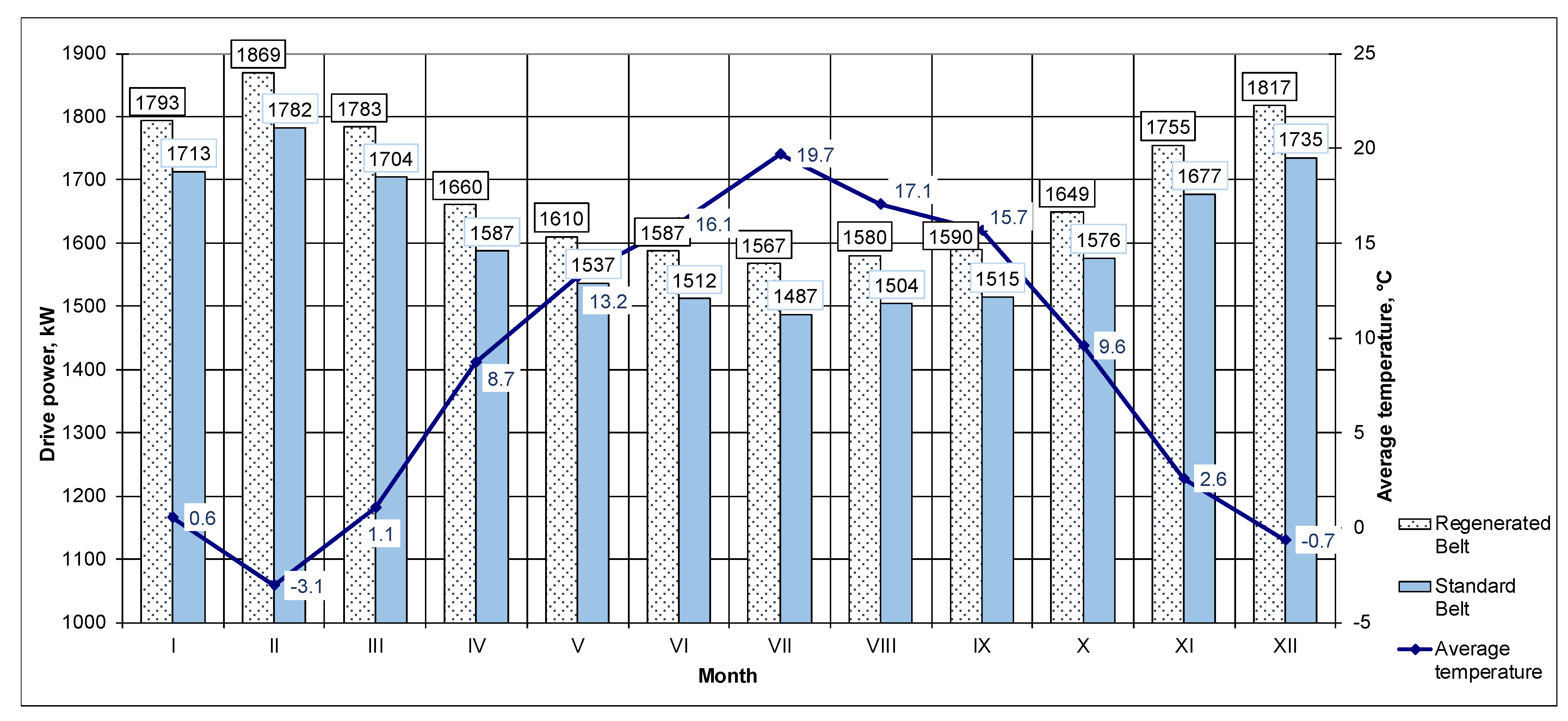
Figure 5 shows a comparison of the power demand from a conveyor drive mechanism for the 1-ST standard belt used in lignite mines and for the 4-EO energy-saving belt. The power of the conveyor drive mechanism is shown against the mean ambient temperature in successive months of the year. The blue line indicates mean monthly temperatures in the area of the Belchatow mine. The bottom cover of the 1-ST belt is made of a rubber compound commonly used by the manufacturer of this type of belts. The bottom cover of the 4-EO belt has lower rolling resistance values in comparison to the standard 1-ST belt.
Figure 6 shows a comparison of the power demand from a conveyor drive mechanism for the 1-ST standard belt and for the 1-ST-R1 refurbished belt used in lignite mines. The bottom cover of this belt is manufactured from a rubber compound which has the highest rolling resistance values of all the tested belts.
In comparison to the standard belt, the refurbished belt generates, on average per annum, a power demand higher by approximately 4.8%.
By installing a steel-cord conveyor belt with the lowest indentation rolling resistance and the highest energy-efficiency, in place of the standard belt used to date in the mine, the power consumption of the conveyor drive mechanism can be reduced by approximately 15.3% on average per annum. If this belt is used in place of the refurbished belt, the power demand is reduced by more than 20%.
Although it generates lower belt indentation rolling resistances, the energy-saving belt is more sensitive to ambient temperatures in comparison to the standard belt and to the refurbished belt. The power consumption difference within the range of extreme temperatures observed in February and in July was 374 kW for the energy-saving belt, 295 kW for the standard belt and 302 kW for the refurbished belt.
The proposed method for measuring belt indentation rolling resistance on the “inclined plane” test rig is the result of long-lasting research into belt conveyor resistance to motion, performed at Wroclaw University of Science and Technology [
50,
51]. Acquiring proper dimensions of the conveyor drive mechanism is a very important design task. It can be performed based on conveyor resistances to motion. These resistances can be most advantageously estimated from unit resistance methods, which were developed at different research centers [
52]. The improvement of the calculation methods to verify the identified relationships requires laboratory tests. This article presented an experimental test method for measuring the greatest component of conveyor belt motion resistances, i.e., indentation rolling resistances. This method consisted in measuring a carriage with two idlers rolling on the conveyor belt. The obtained results may serve not only to verify the calculation methods, but also to compare the rolling resistances of different belt types and designs. The identification of the impact of various factors on belt indentation rolling resistances is also a basis for any activities aimed at finding solutions to help reduce the electric energy consumption of belt conveyor drive mechanisms.
5. Conclusions
The “inclined plane” test rig developed for the purpose of identifying belt indentation rolling resistances allowed quick and easy measurements. Tests performed with the use of this “inclined plane” may help research optimal parameters for rubber compounds and optimal design solutions for conveyor belt bottom covers.
A complex analysis of the influence of the bottom cover design and of the rubber compounds used in bottom covers on indentation rolling resistances must include a number of criteria, such as the sensitivity of rubber compounds to temperature changes. The operating temperature of a particular conveyor thus becomes an important factor.
The power consumption of conveyor drive mechanisms is possible if the rubber used in the bottom cover of a steel-cord belt has appropriately selected mechanical parameters that reduce indentation rolling resistances. At a mean annual temperature of 8.3 °C, if a standard belt used to date in Polish lignite mines is replaced with an energy-saving belt with a bottom cover generating lower indentation rolling resistances, the power consumption of the conveyor main drive mechanism can be reduced by approximately 15%.
Refurbished conveyor belts should be withdrawn from service. They generate higher rolling resistances and thus increase the power consumption of conveyor drive mechanisms. The application scale of refurbished belts at the Belchatow mine, where they account for 40% of all operated steel-cord belts, causes their operating cost to be very high.


