Heat Transfer in Flow Past Two Cylinders in Tandem and Enhancement with a Slit

Abstract
:1. Introduction
2. Numerical Method
2.1. Nusselt Number
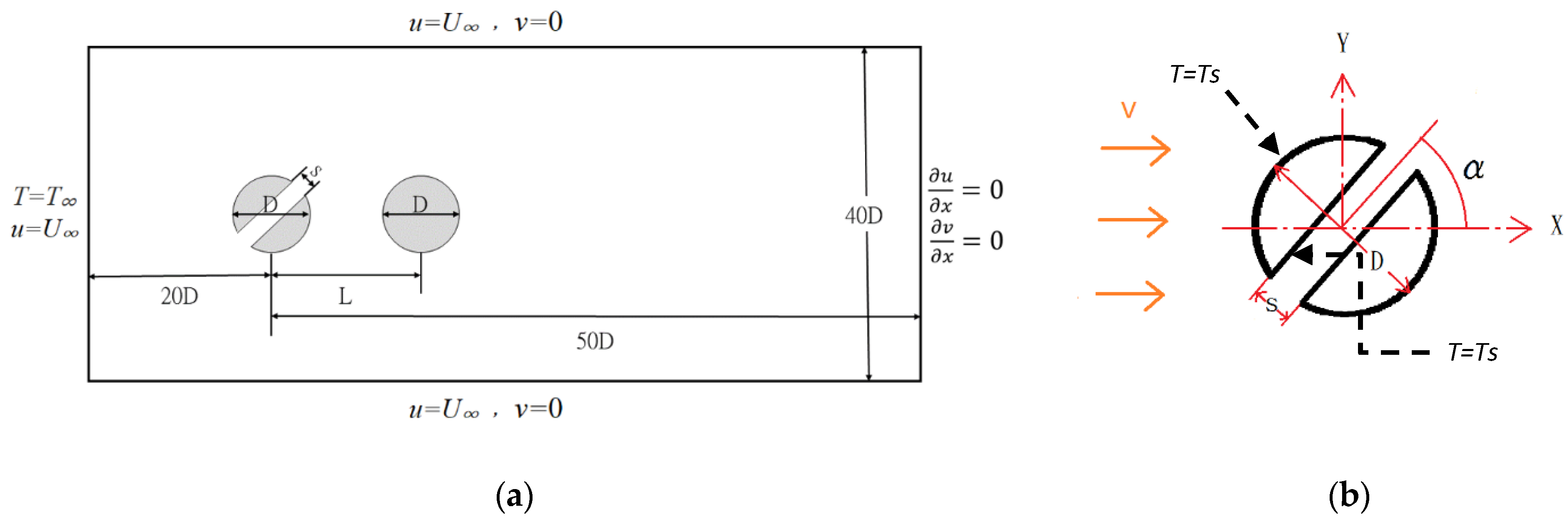
2.2. Boundary Conditions for Heat Transfer
3. Validation
3.1. Grid Independence
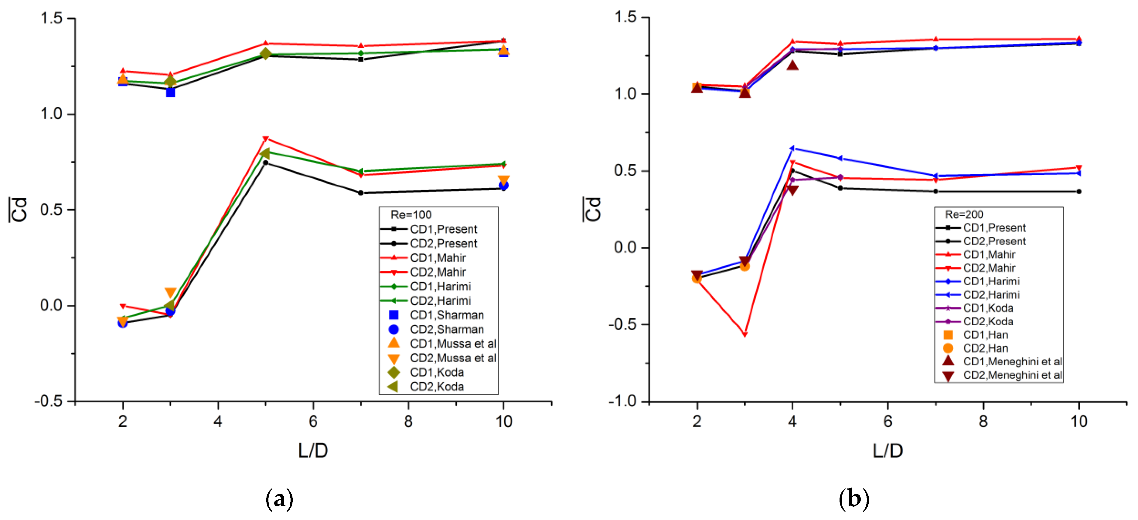
3.2. Validation
4. Results and Discussion
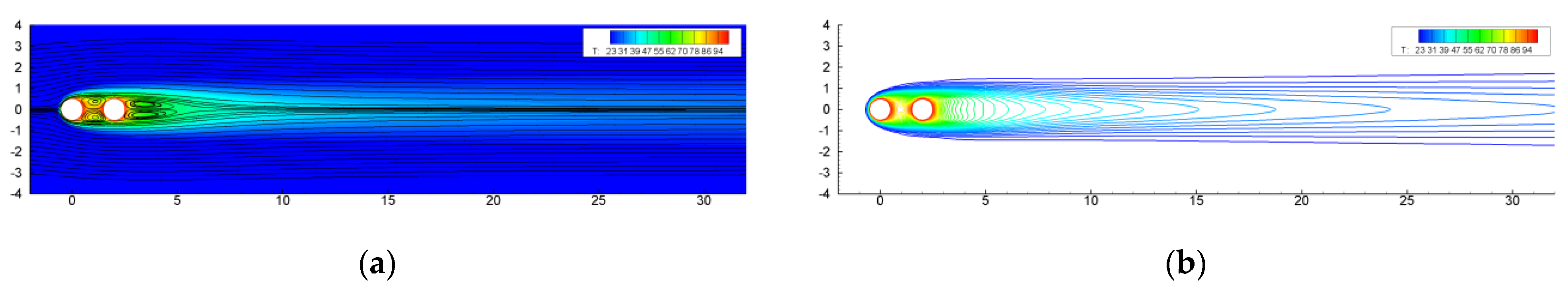
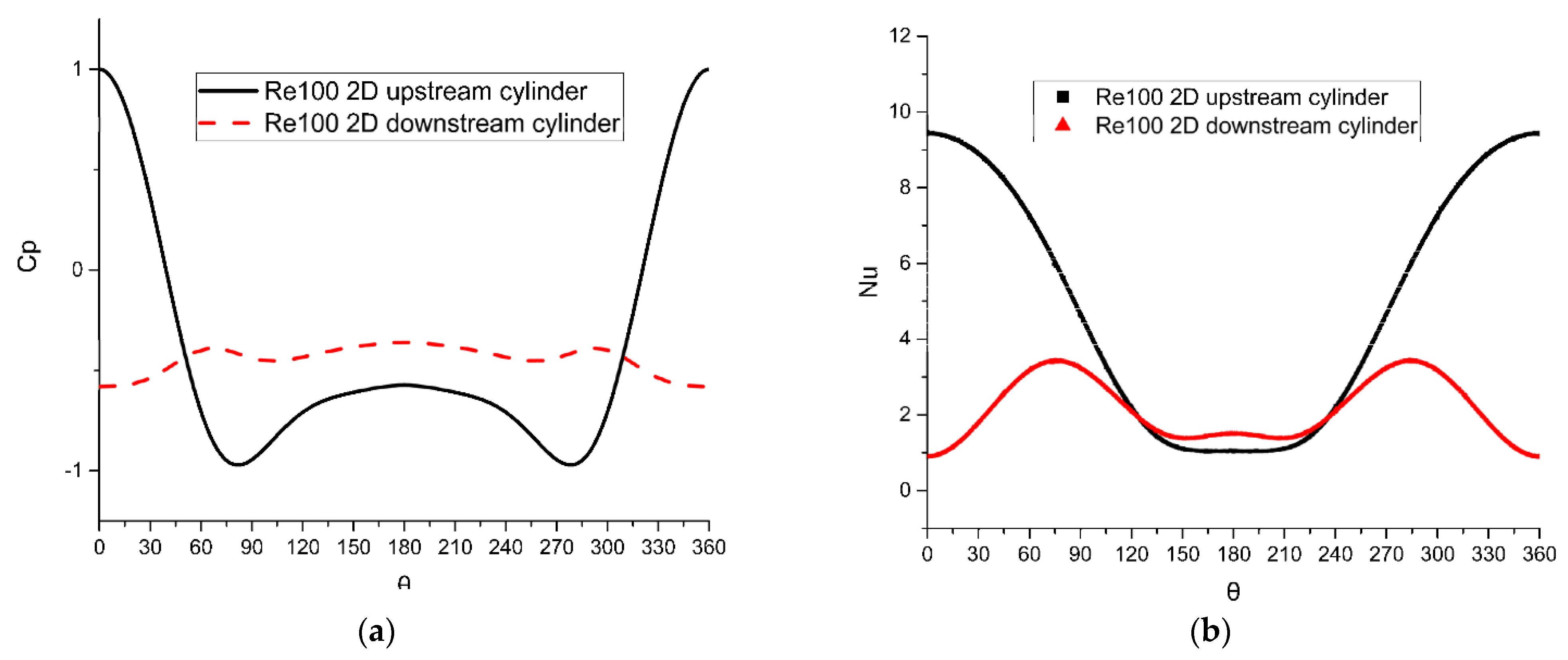
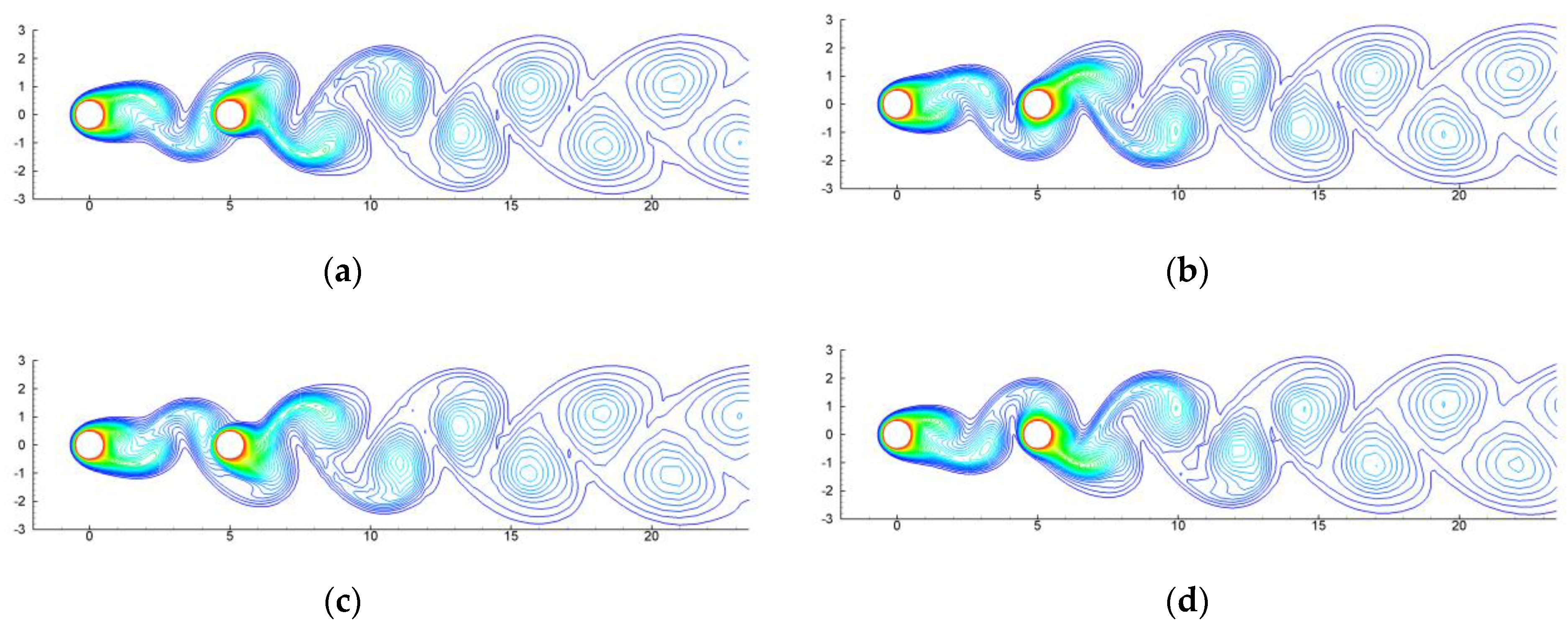
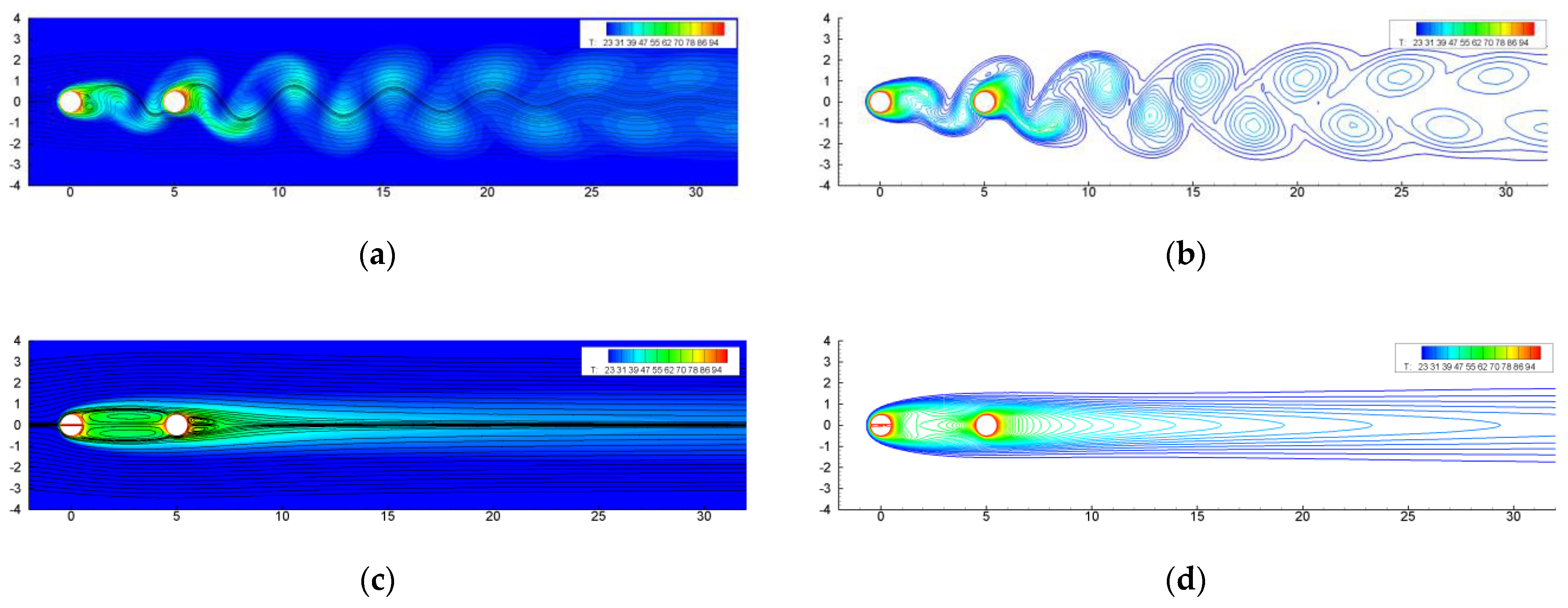
4.1. Flow Patterns and Heat Transfer of Tandem Regular Cylinders
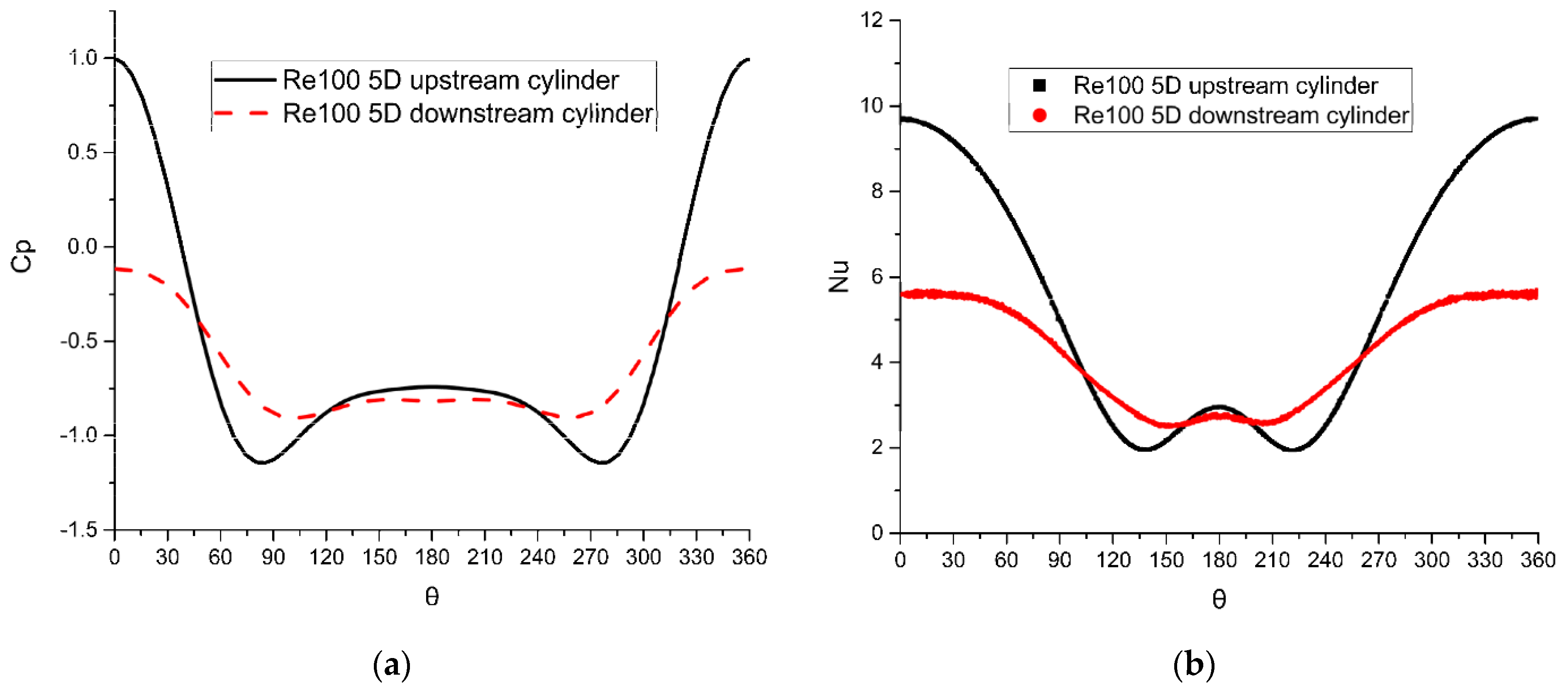
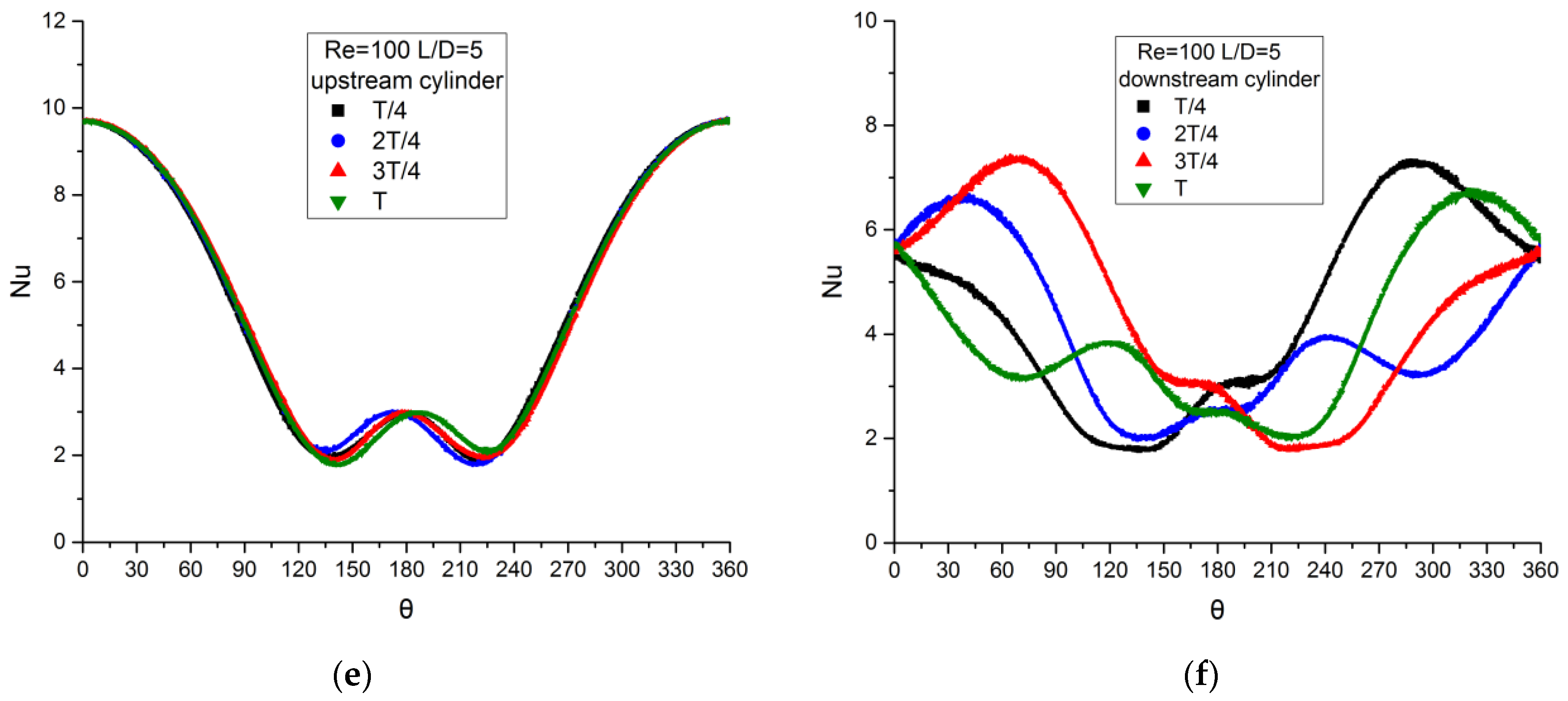
4.1.1. Re = 100
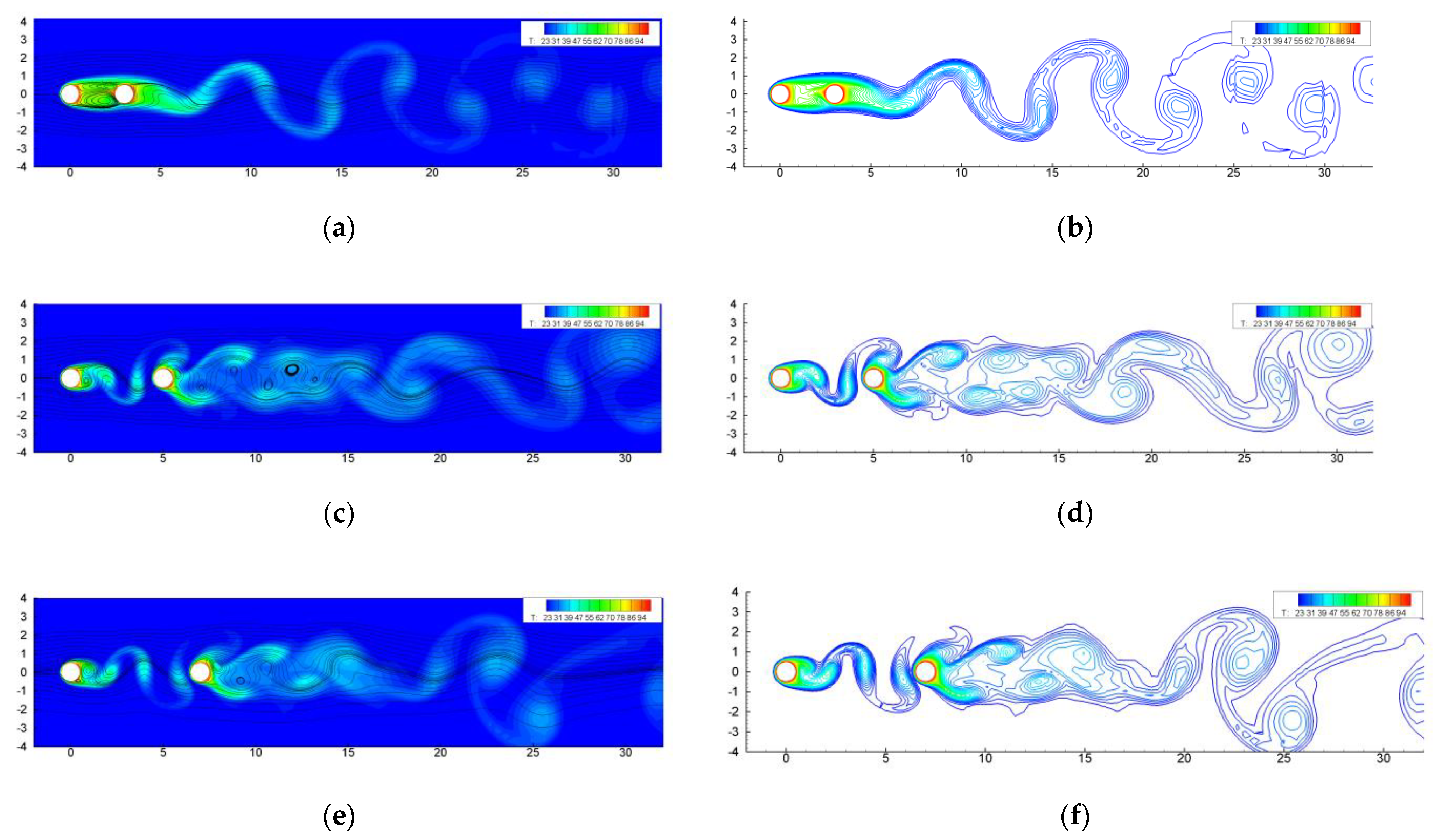
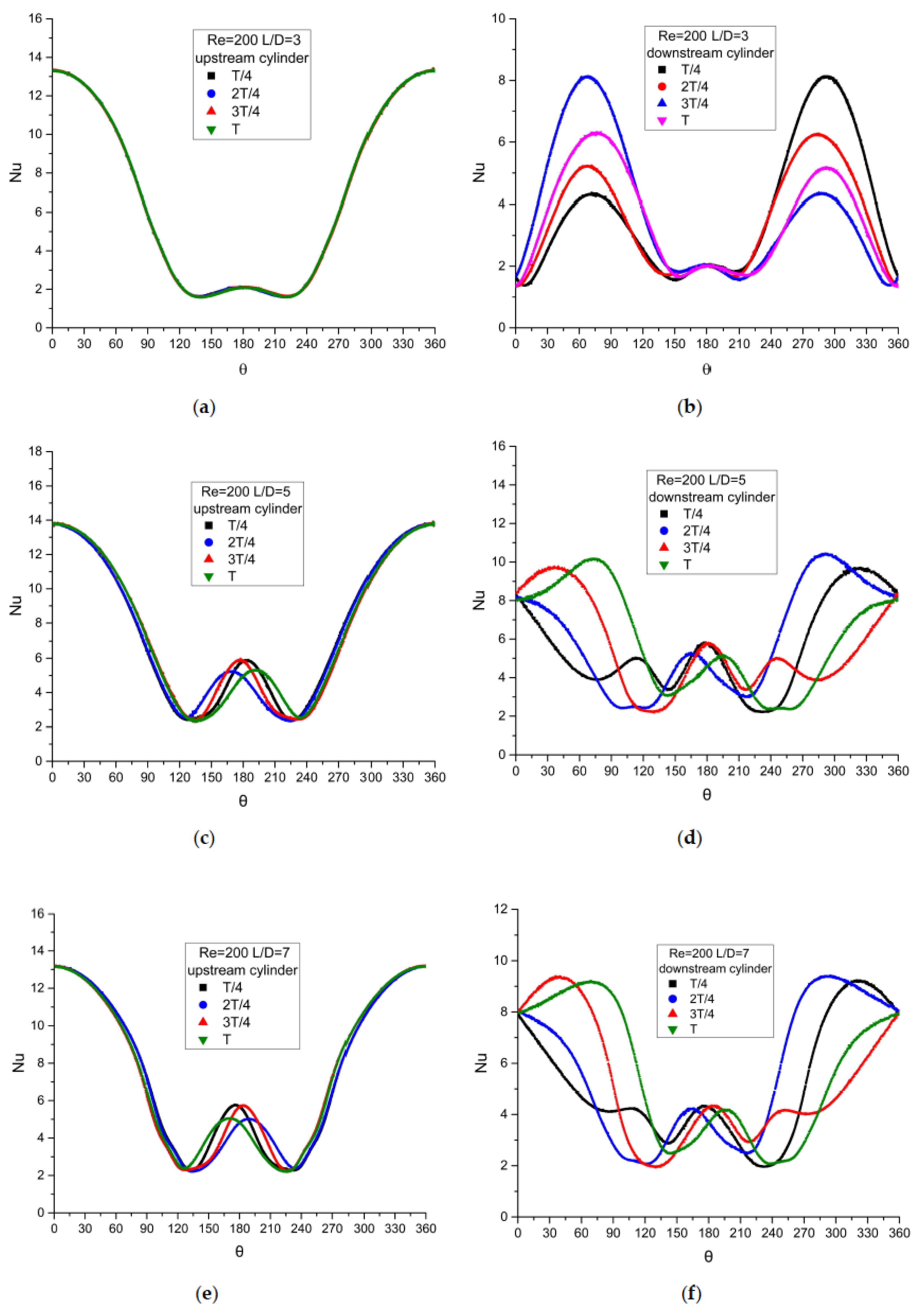
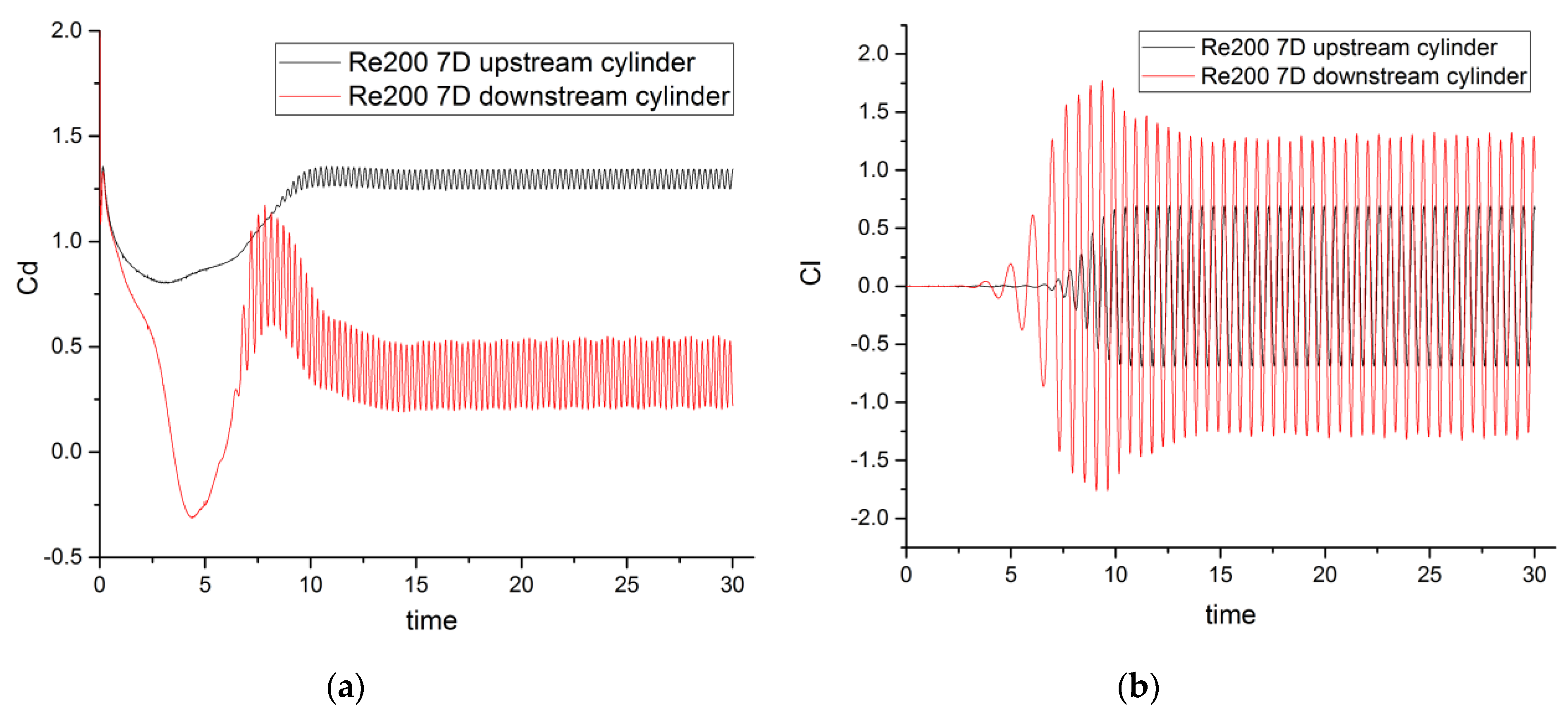
4.1.2. Re = 200
The Characteristics of Tandem Array
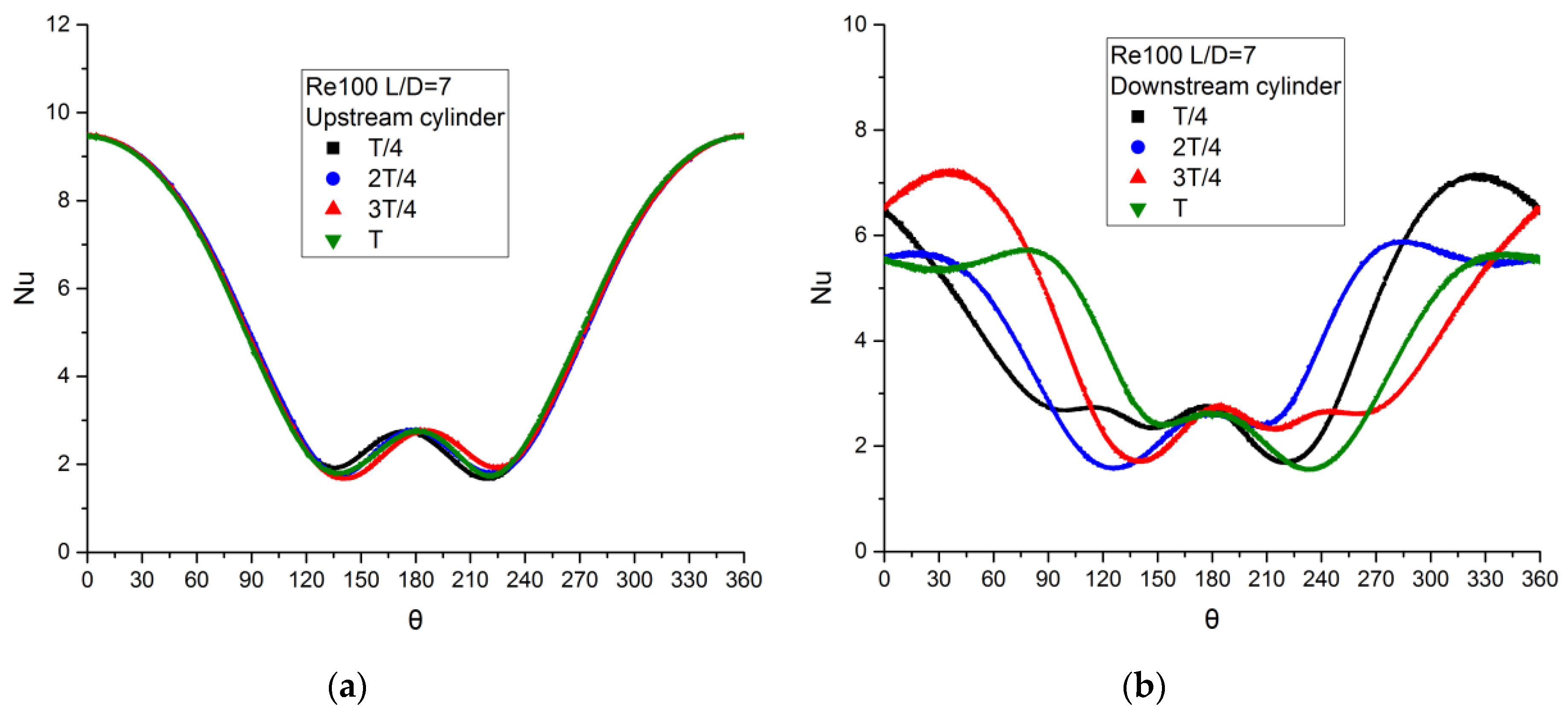
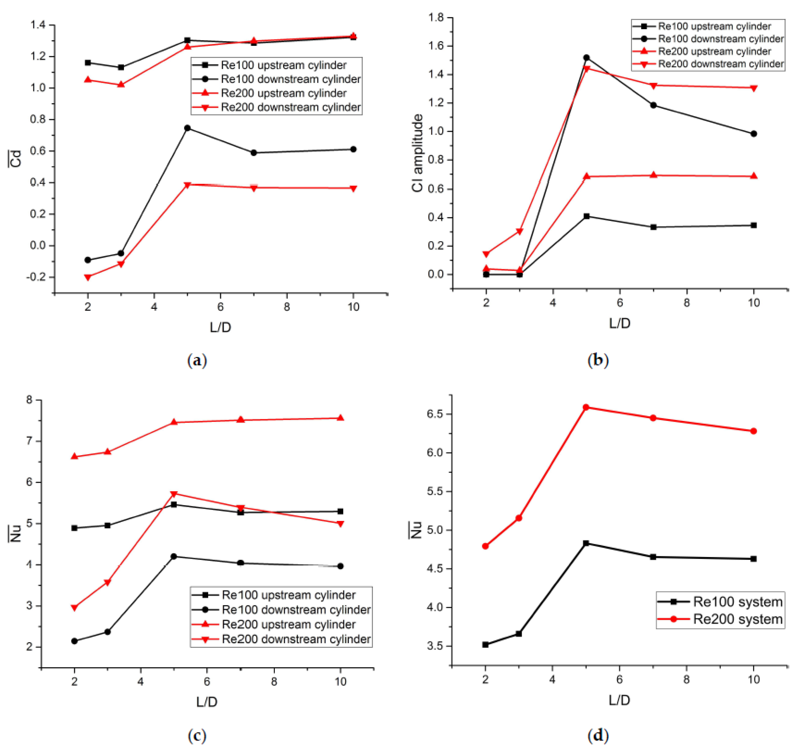
Effect of Distance
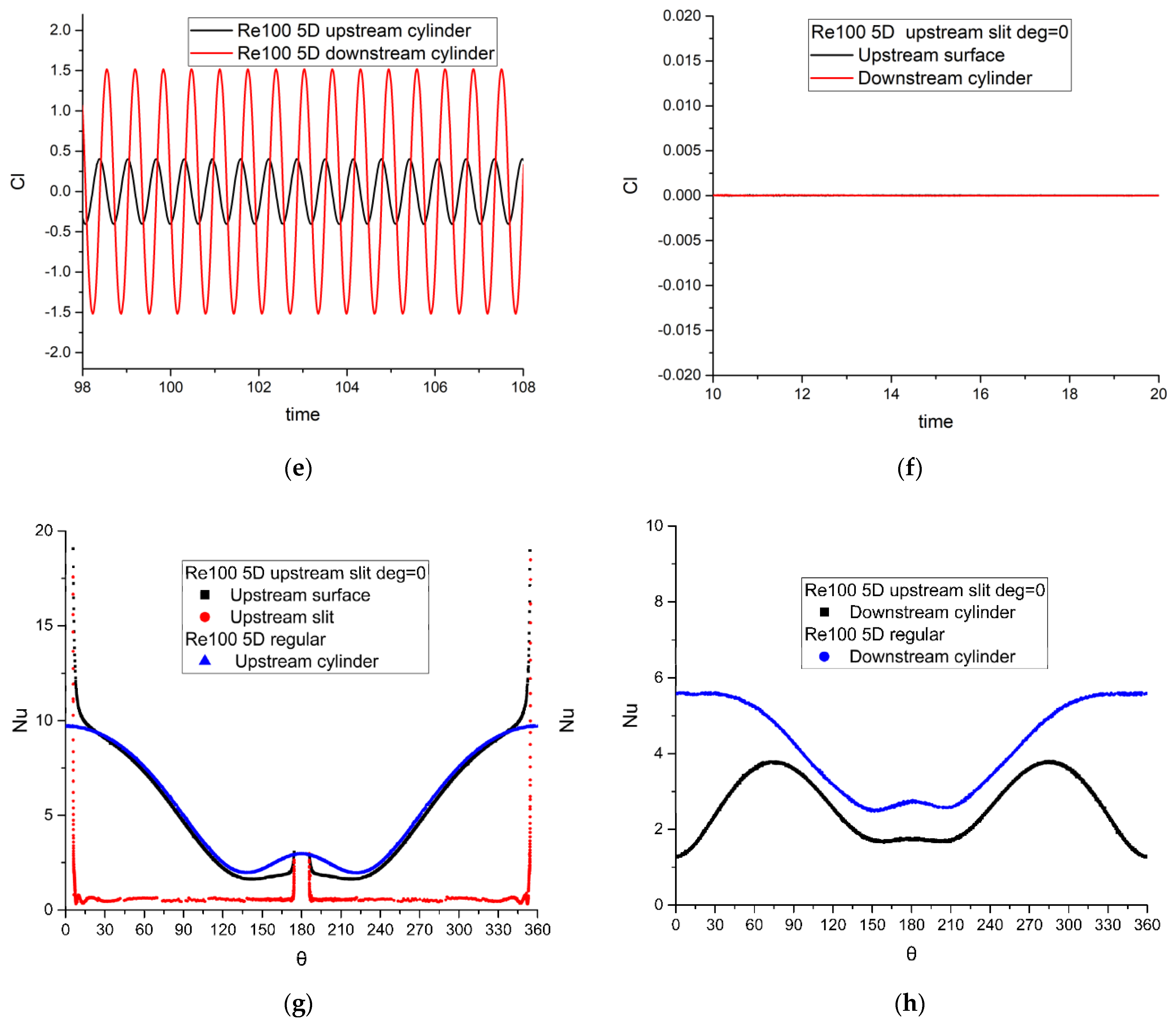
4.2. Flow Patterns and Heat Transfer of Tandem Slotted Cylinders
4.2.1. Flow Pattern Transform
- (i)
- Suppression
- (ii)
- Revival
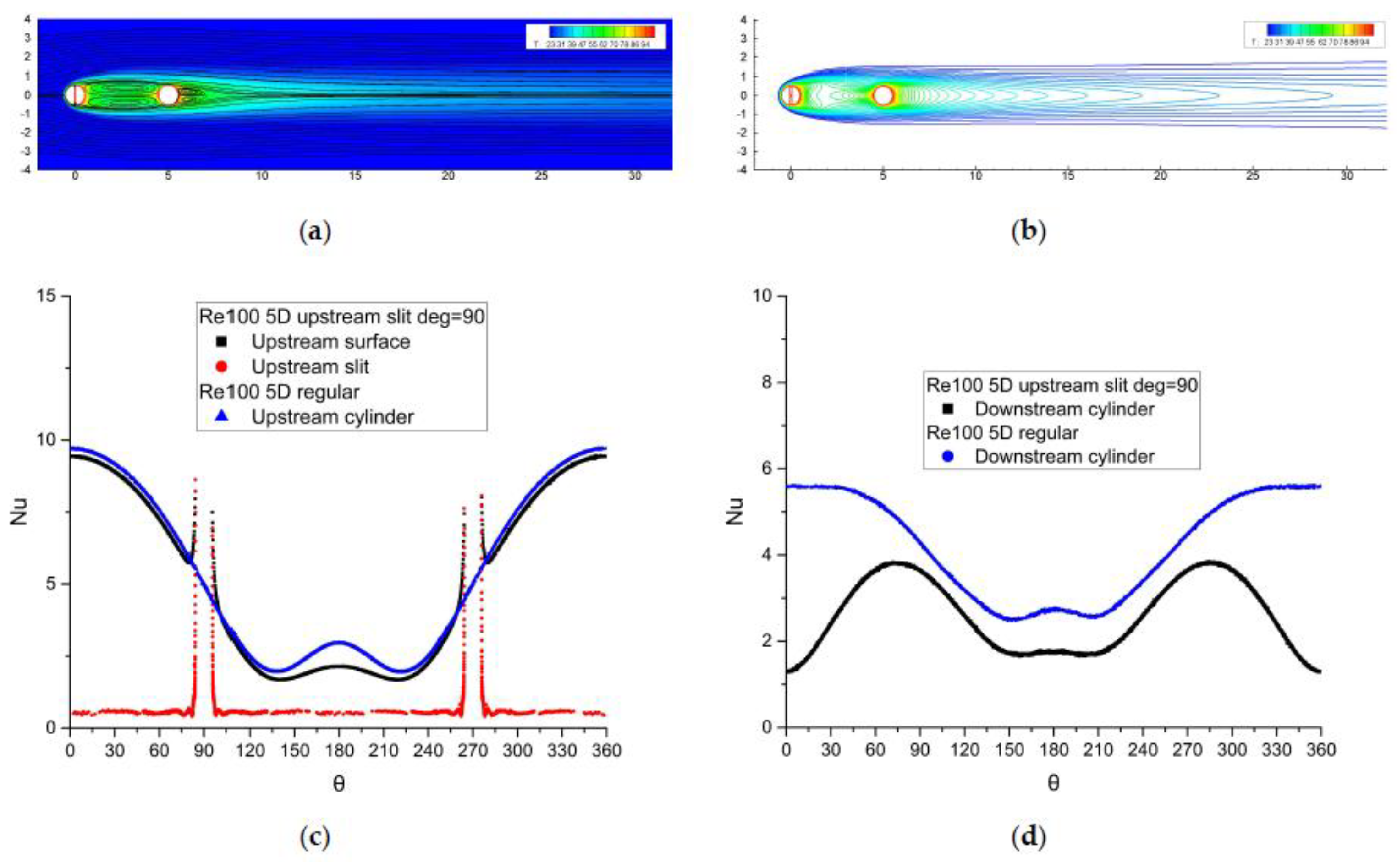
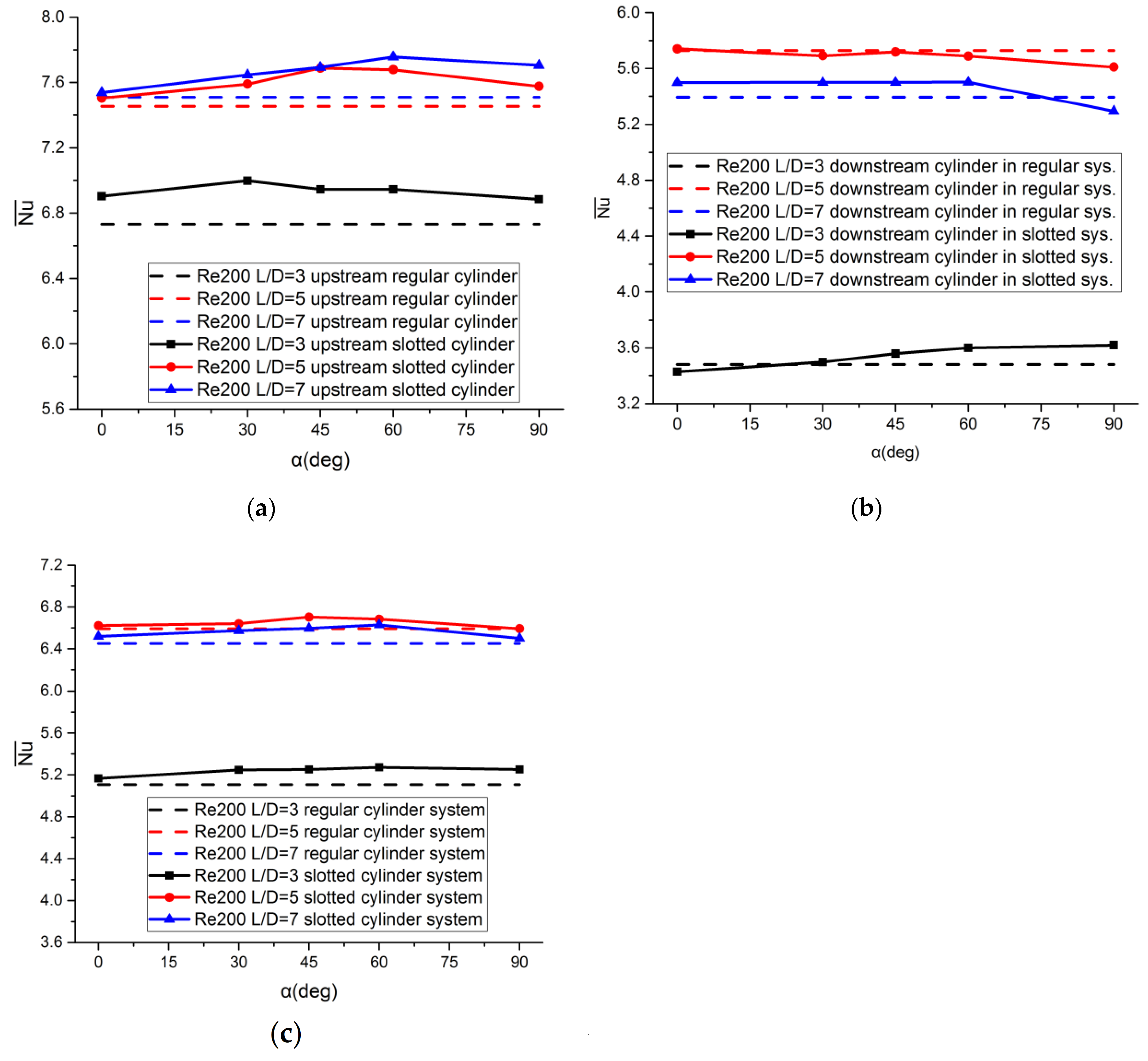
4.2.2. Effect of the Inclination of a Slit
4.2.3. Effect of Distance Ratio
5. Conclusions
Author Contributions
Funding
Institutional Review Board Statement
Informed Consent Statement
Data Availability Statement
Acknowledgments
Conflicts of Interest
References
- John, T.; Mathew, B.; Hegab, H. Parametric study on the combined thermal and hydraulic performance of single phase micro pin-fin heat sinks part I: Square and circle geometries. Int. J. Therm. Sci. 2010, 49, 2177–2190. [Google Scholar] [CrossRef]
- Seyf, H.R.; Feizbakhshi, M. Computational analysis of nanofluid effects on convective heat transfer enhancement of micro-pin-fin heat sinks. Int. J. Therm. Sci. 2012, 58, 168–179. [Google Scholar] [CrossRef]
- Shafeie, H.; Abouali, O.; Jafarpur, K.; Ahmadi, G. Numerical study of heat transfer performance of single-phase heat sinks with micro pin-fin structures. Appl. Therm. Eng. 2013, 58, 68–76. [Google Scholar] [CrossRef]
- Sharman, B.; Lien, F.S.; Davidson, L.; Norberg, C. Numerical predictions of low Reynolds number flows over two tandem circular cylinders. Int. J. Numer. Methods Fluids 2005, 47, 423–447. [Google Scholar] [CrossRef]
- Wang, J.; Zhang, P.F.; Lu, S.F.; Wu, K. Drag Reduction of a Circular Cylinder Using an Upstream Rod. Flow Turbul. Combust. 2006, 76, 83–101. [Google Scholar] [CrossRef]
- Alam, M.M.; Zhou, Y. Strouhal numbers, forces and flow structures around two tandem cylinders of different diameters. J. Fluids Struct. 2008, 24, 505–526. [Google Scholar] [CrossRef]
- Jiang, R.; Lin, J.; Ku, X. Numerical predictions of flows past two tandem cylinders of different diameters under unconfined and confined flows. Fluid Dyn. Res. 2014, 46, 025506. [Google Scholar] [CrossRef]
- Buyruk, E. Numerical Study of Heat Transfer Characteristics on Tandem Cylinders, inline and Staggered Tube Banks in Cross-flow of Air. Int. Commun. Heat Mass Transf. 2002, 29, 355–366. [Google Scholar] [CrossRef]
- Harimi, I.; Saghafian, M. Numerical simulation of fluid flow and forced convection heat transfer from tandem circular cylinders using overset grid method. J. Fluids Struct. 2012, 28, 309–327. [Google Scholar] [CrossRef]
- Mahir, N.; Altaç, Z. Numerical investigation of convective heat transfer in unsteady flow past two cylinders in tandem arrangements. Int. J. Heat Fluid Flow 2008, 29, 1309–1318. [Google Scholar] [CrossRef]
- Zhou, S.-D.; Xi, G. Numerical study on characteristics of flow and thermal fields of offset cylinder arrays in the middle Reynolds number range. Int. J. Refrig. 2016, 65, 69–79. [Google Scholar] [CrossRef]
- Tsutsui, T.; Igarashi, T. Heat Transfer Enhancement of a Circular Cylinder. J. Heat Transf. 2005, 128, 226–233. [Google Scholar] [CrossRef]
- Ma, H.; Oztekin, D.E.; Bayraktar, S.; Yayla, S.; Oztekin, A. Computational Fluid Dynamics and Heat Transfer Analysis for a Novel Heat Exchanger. J. Heat Transf. 2015, 137, 051801. [Google Scholar] [CrossRef] [Green Version]
- Al-Damook, A.; Kapur, N.; Summers, J.; Thompson, H. An experimental and computational investigation of thermal air flows through perforated pin heat sinks. Appl. Therm. Eng. 2015, 89, 365–376. [Google Scholar] [CrossRef]
- Wu, C.-H.; Tang, H.-W.; Yang, Y.-T. Numerical simulation and optimization of turbulent flows through perforated circular pin fin heat sinks. Numer. Heat Transfer Part A Appl. 2017, 71, 172–188. [Google Scholar] [CrossRef]
- Hsu, L.-C. Heat transfer of flow past a cylinder with a slit. Int. J. Therm. Sci. 2021, 159, 106582. [Google Scholar] [CrossRef]
- Hsu, L.-C.; Chen, C.-L. The drag and lift characteristics of flow around a circular cylinder with a slit. Eur. J. Mech. B Fluids 2020, 82, 135–155. [Google Scholar] [CrossRef]
- Orszag, S.A.; Kells, L.C. Transition to turbulence in plane poiseuille and plane couette flow. J. Fluid Mech. 1980, 96, 159–205. [Google Scholar] [CrossRef] [Green Version]
- Posdziech, O.; Grundmann, R. A systematic approach to the numerical calculation of fundamental quantities of the two-dimensional flow over a circular cylinder. J. Fluids Struct. 2007, 23, 479–499. [Google Scholar] [CrossRef]
- Koda, Y.; Lien, F.-S. Aerodynamic effects of the early three-dimensional instabilities in the flow over one and two circular cylinders in tandem predicted by the lattice Boltzmann method. Comput. Fluids 2013, 74, 32–43. [Google Scholar] [CrossRef]
- Mussa, A.; Asinari, P.; Luo, L.-S. Lattice Boltzmann simulations of 2D laminar flows past two tandem cylinders. J. Comput. Phys. 2009, 228, 983–999. [Google Scholar] [CrossRef] [Green Version]
- Meneghini, J.R.; Saltara, F. Numerical simulation of flow interference between two circular cylinders in tandem and side-by-side arrangements. J. Fluids Struct. 2001, 15, 327–350. [Google Scholar] [CrossRef]
- Han, Z.; Zhou, D.; Gui, X.; Tu, J. A numerical study of flow past four square-arranged cylinders using spectral element method. Comput. Fluids 2013, 84, 100–112. [Google Scholar] [CrossRef]
- Zdravkovich, M. The effects of interference between circular cylinders in cross flow. J. Fluids Struct. 1987, 1, 239–261. [Google Scholar] [CrossRef]
- Xu, G.; Zhou, Y. Strouhal numbers in the wake of two inline cylinders. Exp. Fluids 2004, 37, 248–256. [Google Scholar] [CrossRef]
- Zhou, Y.; Yiu, M.W. Flow structure, momentum and heat transport in a two-tandem-cylinder wake. J. Fluid Mech. 2006, 548, 17–48. [Google Scholar] [CrossRef] [Green Version]


| Authors | L/D | Cd1 | Cl1 | Cd2 | Cl2 | St | Nu1 | Nu2 |
|---|---|---|---|---|---|---|---|---|
| Present | 2 | 1.160 | 0 | −0.091 | 0 | 0 | 4.892 | 2.145 |
| Sharman et al. [4] | 2 | 1.169 | −0.090 | 0.121 | ||||
| Mussa et al. [21] | 2 | 1.178 | −0.077 | 0.123 | ||||
| Harimi and Saghafian [9] | 2 | 1.173 | −0.065 | 4.688 | 2.029 | |||
| Mahir and Altac [10] | 2 | 1.225 | ±0.0075 | ±0.00012 | ±0.0258 | 4.74 | 2.03 | |
| Present | 3 | 1.130 | 0 | −0.049 | 0 | 0 | 4.952 | 2.369 |
| Sharman et al. | 3 | 1.111 | −0.027 | 0.109 | ||||
| Koda and Lien [20] | 3 | 1.171 | 0.002 | 0.106 | ||||
| Mussa et al. | 3 | 1.171 | 0.074 | 0.114 | ||||
| Harimi and Saghafian | 3 | 1.160 | 0.0018 | 0.1111 | 4.782 | 2.299 | ||
| Mahir and Altac | 3 | 1.205 | 0 | −0.048 | 0.0014 ± 0.004 | 4.804 | 2.293 | |
| Present | 5 | 1.303 ± 0.015 | ±0.409 | 0.746 ± 0.150 | ±1.519 | 0.1563 | 5.461 | 4.202 |
| Koda and Lien | 5 | 1.316 | 0.793 | 0.149 | ||||
| Harimi and Saghafian | 5 | 1.311 | 0.805 | 0.1568 | 5.028 | 3.264 | ||
| Mahir and Altac | 5 | 1.369 ± 0.013 | ±0.437 | 0.874 ± 0.165 | ±1.617 | 0.161 | 5.180 ± 0.005 | 4.28 ± 0.040 |
| Present | 7 | 1.285 ± 0.011 | ±0.333 | 0.589 ± 0.066 | ±1.184 | 0.1546 | 5.270 | 4.039 |
| Harimi and Saghafian | 7 | 1.317 | 0.701 | 0.1593 | 5.036 | 3.29 | ||
| Mahir and Altac | 7 | 1.355 ± 0.014 | ±0.363 | 0.682 ± 0.07 | ±1.309 | 0.166 | 5.159 ± 0.003 | 4.21 ± 0.26 |
| Present | 10 | 1.322 ± 0.010 | ±0.346 | 0.611 ± 0.073 | ±0.983 | 0.1624 | 5.296 | 3.964 |
| Sharman et al. | 10 | 1.321 | 0.629 | 0.161 | ||||
| Mussa et al | 10 | 1.329 | 0.66 | 0.161 | ||||
| Harimi and Saghafian | 10 | 1.337 | 0.741 | 0.1639 | 5.058 | 3.493 | ||
| Mahir and Altac | 10 | 1.383 ± 0.011 | ±0.359 | 0.731 ± 0.087 | ±1.14 | 0.172 | 5.174 ± 0.003 | 4.27 ± 0.18 |
| Authors | L/D | Cd1 | Cl1 | Cd2 | Cl2 | St | Nu1 | Nu2 |
|---|---|---|---|---|---|---|---|---|
| Present | 2 | 1.051 ± 0.009 | ±0.039 | −0.197 ± 0.006 | ±0.147 | 0.1304 | 6.618 | 2.97 |
| Mahir and Altac [10] | 2 | 1.06 ± 0.0004 | ±0.034 | - 0.21 ± 0.0036 | ±0.17 | 6.460 | 2.88 ± 0.03 | |
| Harimi and Saghafian [9] | 2 | 1.038 | −0.175 | 6.359 | 2.82 | |||
| Meneghini and Saltara [22] | 2 | 1.03 | −0.17 | 0.130 | ||||
| Han et al. [23] | 2 | 1.041 | −0.199 | 0.132 | ||||
| Present | 3 | 1.020 ± 0.011 | ±0.029 | −0.114 ± 0.014 | ±0.306 | 0.1244 | 6.733 | 3.481 |
| Mahir and Altac | 3 | 1.051 ± 0.025 | ±0.029 | −0.56 ± 0.012 | ±0.269 | 0.130 | 6.56 ± 0.001 | 3.54 ± 0.11 |
| Harimi and Saghafian | 3 | 1.016 | −0.085 | 6.482 | 3.388 | |||
| Koda and Lien [20] | 3 | 1.043 | 0.023 | −0.129 | 0.212 | |||
| Meneghini and Saltara | 3 | 1.0 | −0.08 | 0.125 | ||||
| Han et al. | 3 | 1.005 | −0.119 | 0.127 | ||||
| Present | 4 | 1.278 ± 0.053 | ±0.768 | 0.502 ± 0.4 | ±1.775 | 0.1809 | 7.41 | 5.46 |
| Harimi and Saghafian | 4 | 1.291 | 0.648 | 6.981 | 4.234 | |||
| Mahir and Altac | 4 | 1.34 ± 0.056 | ±0.805 | 0.558 ± 0.22 | ±1.99 | 0.181 | 7.44 ± 0.046 | 6.15 ± 0.51 |
| Koda and Lien | 4 | 1.287 | 0.442 | |||||
| Meneghini and Saltara | 4 | 1.18 | 0.38 | 0.174 | ||||
| Present | 5 | 1.259 ± 0.051 | ±0.682 | 0.388 ± 0.156 | ±1.444 | 0.1801 | 7.455 | 5.728 |
| Mahir and Altac | 5 | 1.327 ± 0.055 | ±0.731 | 0.455 ± 0.16 | ±1.569 | 0.186 | 7.43 ± 0.034 | 5.96 ± 0.47 |
| Harimi and Saghafian | 5 | 1.291 | 0.583 | 7.027 | 4.427 | |||
| Koda and Lien | 5 | 1.295 | ±0.489 | 0.459 | ±1.111 | |||
| Present | 7 | 1.298 ± 0.05 | ±0.691 | 0.367 ± 0.166 | ±1.325 | 0.1894 | 7.510 | 5.394 |
| Mahir and Altac | 7 | 1.356 ± 0.049 | ±0.742 | 0.442 ± 0.15 | ±1.328 | 0.194 | 7.45 ± 0.029 | 5.83 ± 0.32 |
| Harimi and Saghafian | 7 | 1.30 | 0.468 | 7.066 | 4.454 | |||
| Present | 10 | 1.329 ± 0.051 | ±0.685 | 0.366 ± 0.168 | ±1.307 | 0.1947 | 7.556 | 5.009 |
| Mahir and Altac | 10 | 1.359 ± 0.054 | ±0.70 | 0.524 ± 0.153 | ±1.287 | 0.191 | 7.46 ± 0.027 | 5.86 ± 0.26 |
| Harimi and Saghafian | 10 | 1.334 | 0.485 | 7.102 | 4.62 |
| Authors | Lfront/D | Lrear/D | Lup/D | Ldown/D |
|---|---|---|---|---|
| Sharmen et al. [4] | 12.5 | 20 | 25 | 25 |
| Mussa et al. [21] | 13.5 | 25.5 | 23.5 | 23.5 |
| Harimi and Saghafian [9] | 15 | 25 | 12 | 12 |
| Mahir and Altac [10] | 8.5 | 20 | 10 | 10 |
| Koda and Lien [20] | 10 | 15 | 20 | 20 |
| Han et al. [23] | 20 | 30 | 20 | 20 |
| Meneghini and Saltara [22] | 10.5 | 10.5 | 10.5 | 25 |
| Present | 20 | 50 | 20 | 20 |
Publisher’s Note: MDPI stays neutral with regard to jurisdictional claims in published maps and institutional affiliations. |
© 2021 by the authors. Licensee MDPI, Basel, Switzerland. This article is an open access article distributed under the terms and conditions of the Creative Commons Attribution (CC BY) license (http://creativecommons.org/licenses/by/4.0/).
Share and Cite
Hsu, L.-C.; Liang, C.-W. Heat Transfer in Flow Past Two Cylinders in Tandem and Enhancement with a Slit. Energies 2021, 14, 308. https://doi.org/10.3390/en14020308
Hsu L-C, Liang C-W. Heat Transfer in Flow Past Two Cylinders in Tandem and Enhancement with a Slit. Energies. 2021; 14(2):308. https://doi.org/10.3390/en14020308
Chicago/Turabian StyleHsu, Li-Chieh, and Che-Wei Liang. 2021. "Heat Transfer in Flow Past Two Cylinders in Tandem and Enhancement with a Slit" Energies 14, no. 2: 308. https://doi.org/10.3390/en14020308
APA StyleHsu, L.-C., & Liang, C.-W. (2021). Heat Transfer in Flow Past Two Cylinders in Tandem and Enhancement with a Slit. Energies, 14(2), 308. https://doi.org/10.3390/en14020308