Determination of Optimum Envelope of Religious Buildings in Terms of Thermal Comfort and Energy Consumption: Mosque Cases


Abstract
:1. Introduction
2. Materials and Methods
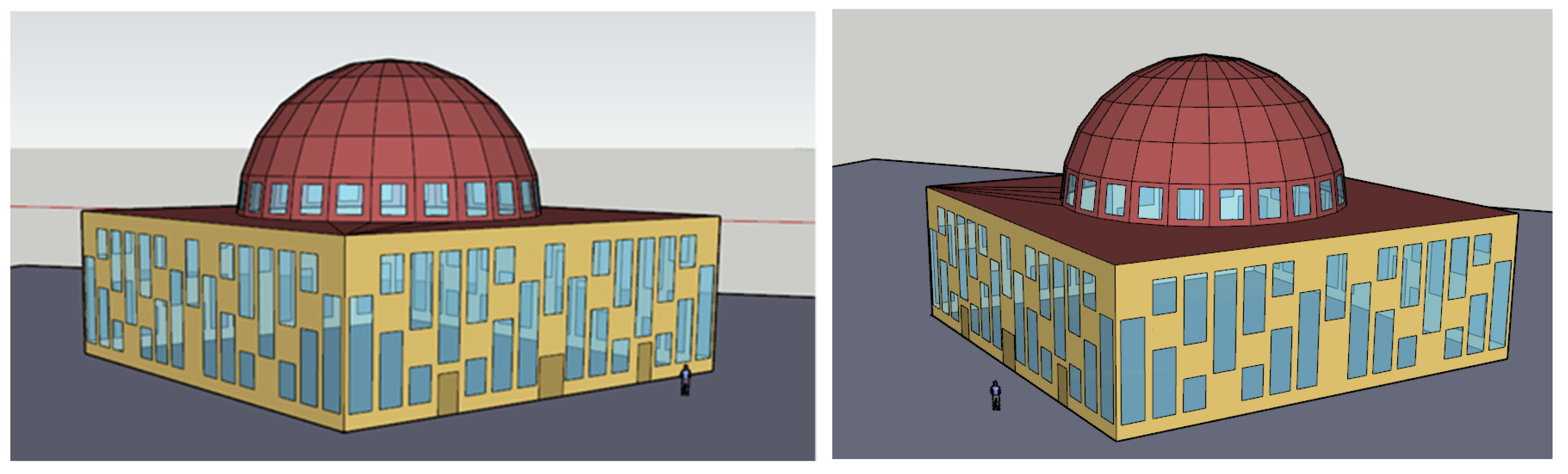
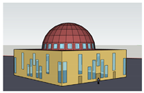
2.1. Introduction of Physical Characteristics and Determination of Base Scenario Properties
Determination of Base Scenario Properties
2.2. Other Scenarios Depended on Building Envelope Parameter Change
- Scenarios where the same transparent ratios were applied on all façades were 25%, 50%, and 75%.
- The very small rate on the northern façade was kept constant at 15%, while the other façades were scenarios as 25% (small) and 50% (medium).
3. Results and Discussion
3.1. Effect of Material Properties Change in Base Scenario
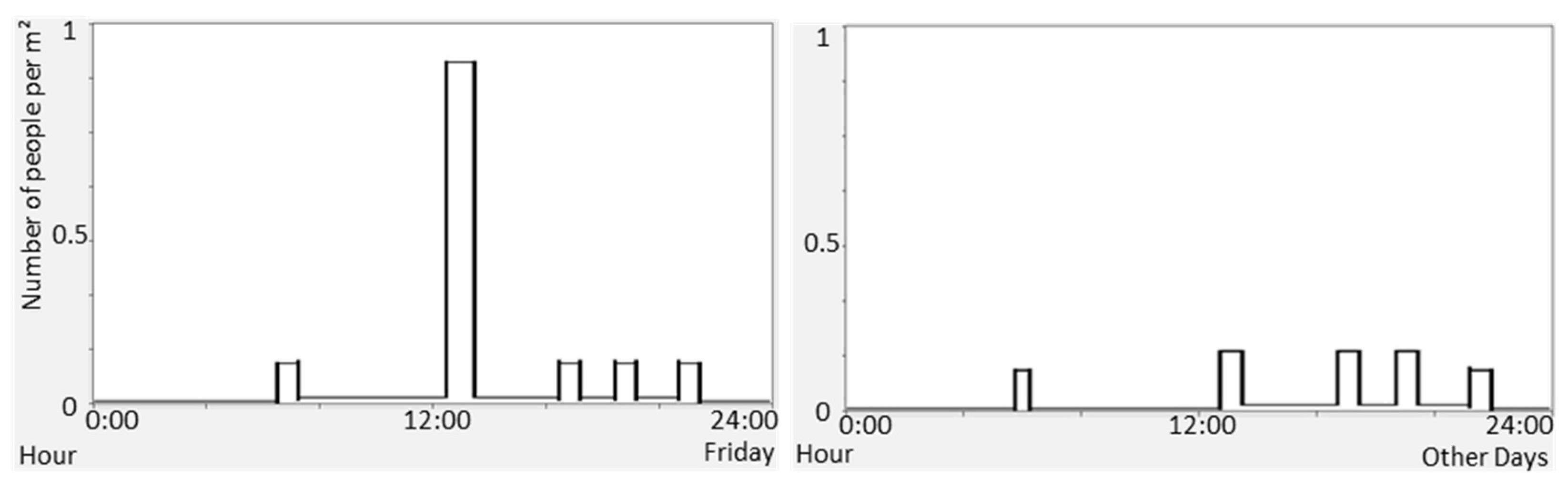
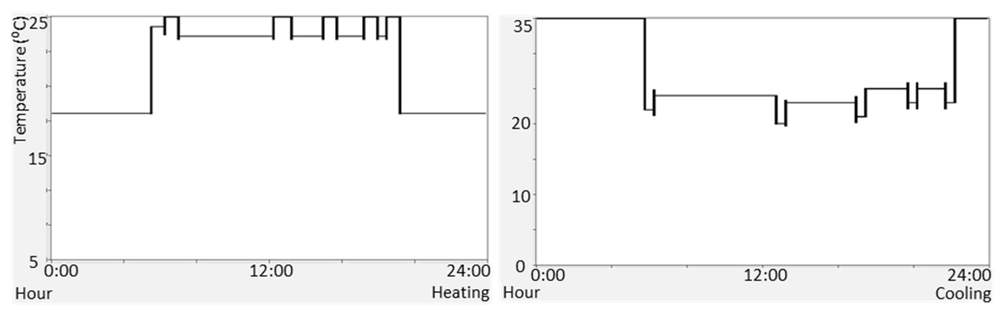
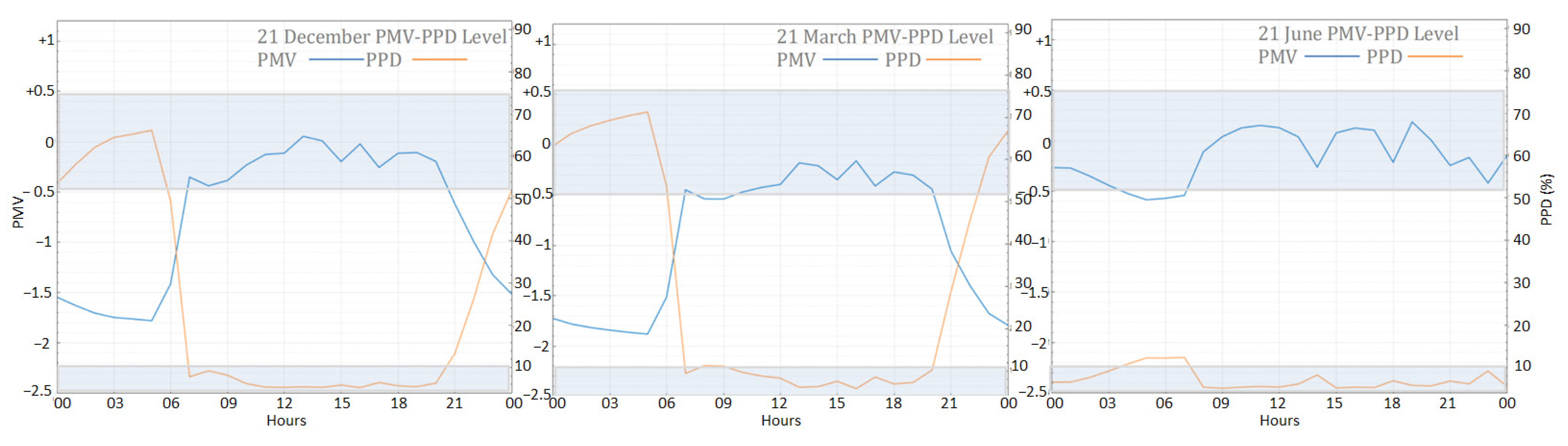
3.2. Thermal Comfort and Energy Consumption of Base Scenario
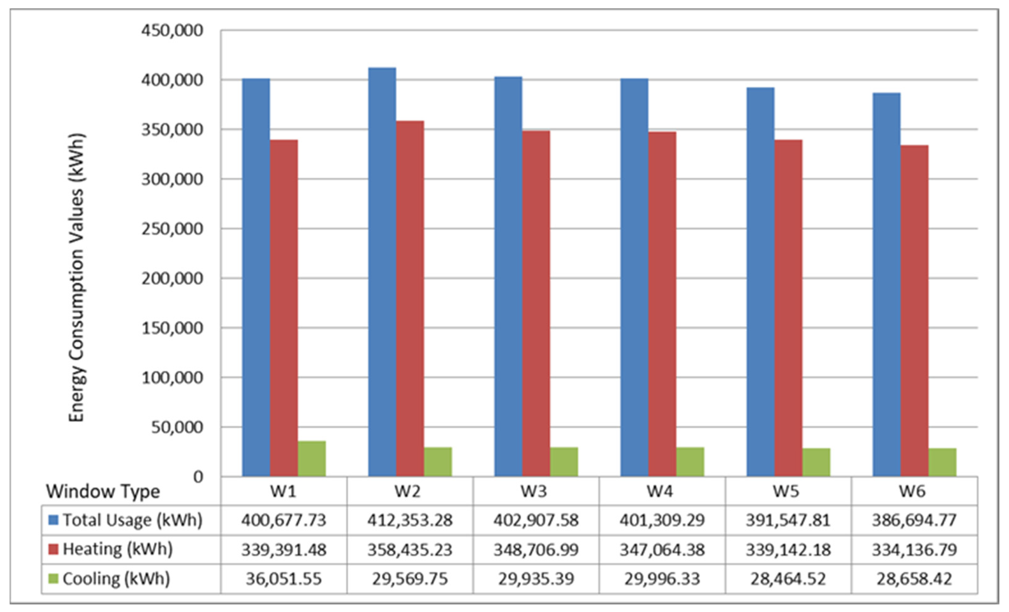
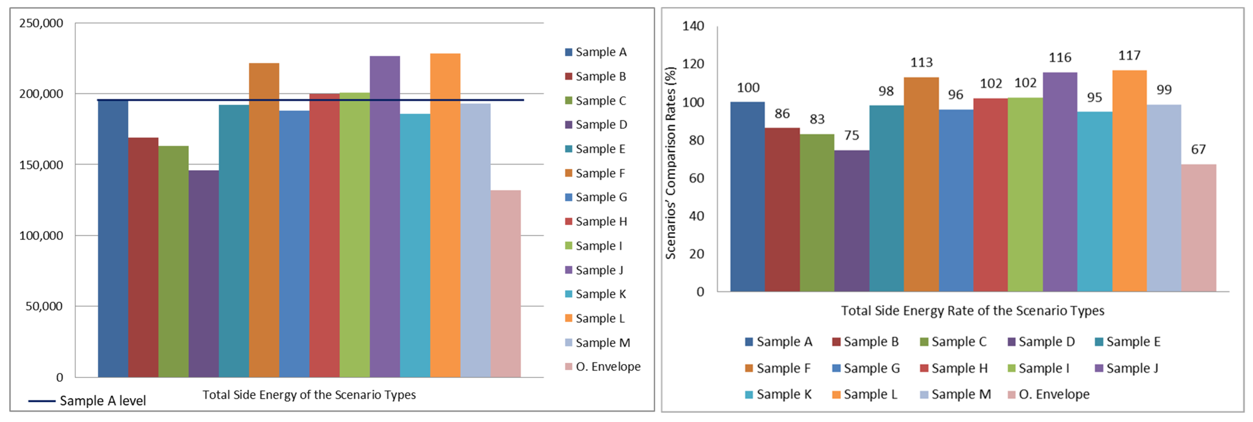
3.3. Comparing to Energy Consumption Data of Other Design Scenarios
4. Conclusions
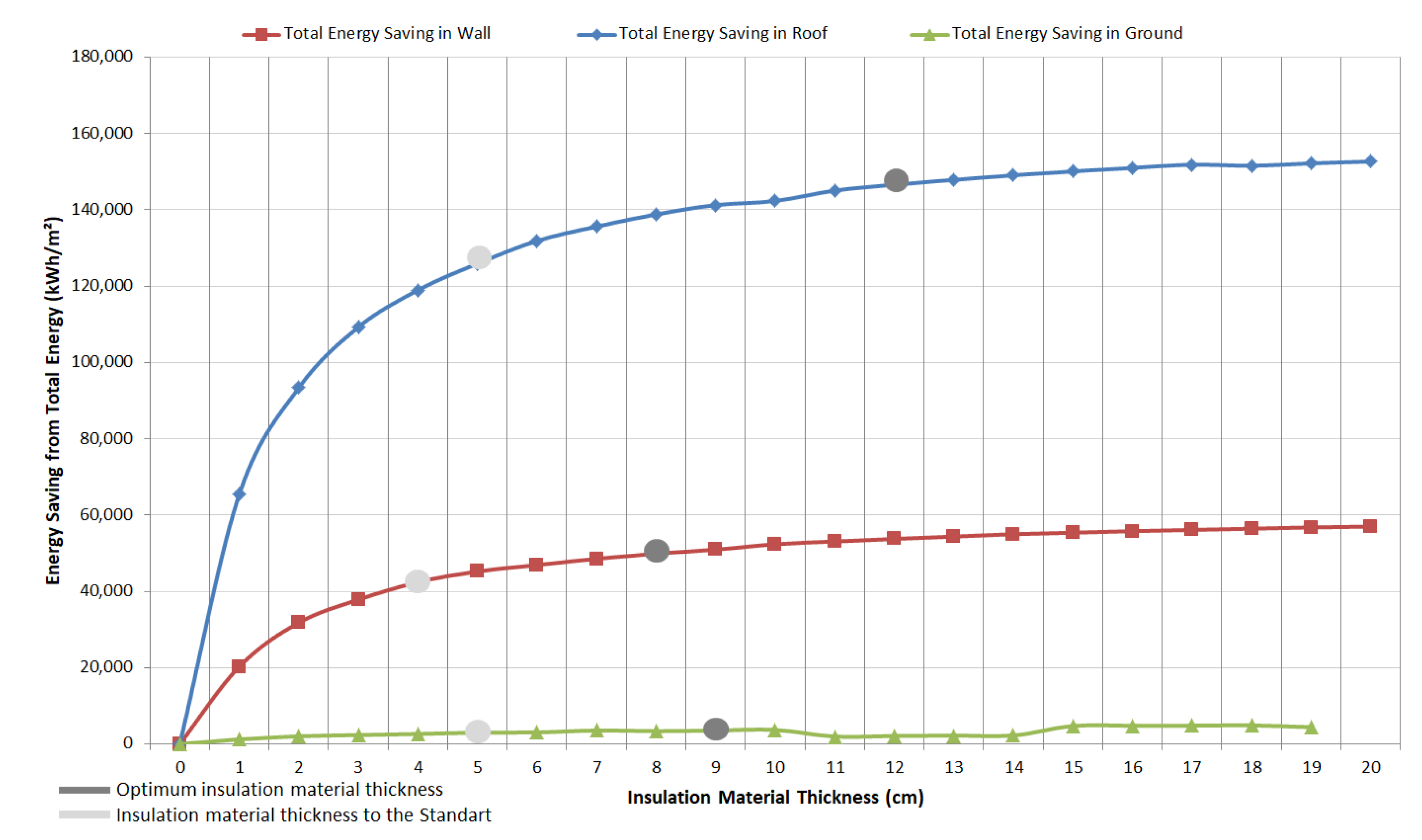
- Thermal insulation improvements to be made in the roof dome organization of buildings with a large volume, such as mosques, contributed more to energy savings than to walls and foundations.
- The increasing thickness of the thermal insulation material used in the building envelope contributed positively to energy saving. However, the energy saving rate decreased after a certain thickness (wall U-value 50 mm-0.48 W/m2K, roof U-value 90 mm-0.32 W/m2K).
- The thickness of the thermal insulation of the floor had only a minimal effect on energy savings.
- Compared to the base scenario, energy consumption decreased by 33% in the optimum envelope scenario with the made improvements.
- While thermal comfort was provided in the 25%, 50%, and 75% options of the building envelope transparent ratio of the mosques, the minimum energy consumption was at a 25% and a 50% transparent ratio.
- Although the cooling energy load in the indoor environment was reduced, reducing the transparent ratio of the building envelope to 15% and 25% increased the heating load.
- The 75% transparent ratio of the building envelope caused 13% more energy consumption compared to the base scenario.
- Without improving the heat transfer coefficient, the use of shading elements with 75% transparency resulted in 16% more energy consumption.
- The use of a shading element in a temperate humid climate reduced the cooling energy load. However, there was an increase in the heating energy load.
- The shading element had the most positive effect in terms of energy consumption when used together with the improvement in the heat transfer coefficient of transparent areas.
- The use of horizontal–vertical or pattern shading elements (with a 50% transparent ratio) in the building envelope resulted in similar energy savings. When considered together with the daylight gain, horizontal and vertical shading elements depending on the directions were found more appropriate within the scope of the study.
- The thermal inertia of building envelope materials was very important in hot climates. In order to investigate it in future studies, the thermal inertia was excluded from the scope of this study.
Author Contributions
Funding
Institutional Review Board Statement
Informed Consent Statement
Data Availability Statement
Acknowledgments
Conflicts of Interest
Nomenclature
| Acronyms | |
| HVAC | Heating, ventilation, and air conditioning |
| AC | Air conditioning |
| CET | Corrected Effective Temperature |
| PMV | Predicted Mean Vote |
| PPD | Predicted Percentage Dissatisfied |
| ASHRAE | American Society of Heating, Refrigerating, and Air-Conditioning Engineers |
| ISO | International Organization for Standardization |
| TS | Turkish Standard |
| SHGC | Solar Heat Gain Coefficient |
| CoP | Coefficient of Performance |
| Meaning | |
| r | Radius |
| m | Meter |
| h | Hour |
| s | Second |
| ach | Air change per hour |
| Units | |
| clo | Clothing insulation |
| met | Metabolic rate |
| 1/h | Air change per hour |
References
- Fanger, P.O. Thermal Comfort: Analysis and Applications in Environmental Engineering; Danish Technical Press: Copenhagen, Denmark, 1972; Volume 3, 244p. [Google Scholar]
- Taleghani, M.; Tenpierik, M.; Kurvers, S.; Dobbelsteen, A.V.D. A review into thermal comfort in buildings. Renew. Sustain. Energy Rev. 2013, 26, 201–215. [Google Scholar] [CrossRef]
- Kim, J.; de Dear, R. Thermal comfort expectations and adaptive behavioural characteristics of primary and secondary school students. Build. Environ. 2018, 127, 13–22. [Google Scholar] [CrossRef]
- Del Ferraro, S.; Iavicoli, S.; Russo, S.; Molinaro, V. A field study on thermal comfort in an Italian hospital considering differences in gender and age. Appl. Ergon. 2015, 50, 177–184. [Google Scholar] [CrossRef] [PubMed]
- Borowski, M.; Łuczak, R.; Halibart, J.; Zwolińska, K.; Karch, M. Airflow Fluctuation from Linear Diffusers in an Office Building: The Thermal Comfort Analysis. Energies 2021, 14, 4808. [Google Scholar] [CrossRef]
- Escandón, R.; Suárez, R.; Sendra, J.J.; Ascione, F.; Bianco, N.; Mauro, G.M. Predicting the Impact of Climate Change on Thermal Comfort in A Building Category: The Case of Linear-type Social Housing Stock in Southern Spain. Energies 2019, 12, 2238. [Google Scholar] [CrossRef] [Green Version]
- Al-Atrash, F.; Hellwig, R.T.; Wagner, A. The degree of adaptive thermal comfort in office workers in a hot-summer Mediterranean climate. Energy Build. 2020, 223, 110147. [Google Scholar] [CrossRef]
- Safizadeh, M.R.; Schweiker, M.; Wagner, A. Experimental Evaluation of Radiant Heating Ceiling Systems Based on Thermal Comfort Criteria. Energies 2018, 11, 2932. [Google Scholar] [CrossRef] [Green Version]
- González, A.G.; García-Sanz-Calcedo, J.; Salgado, D.R. Evaluation of Energy Consumption in German Hospitals: Benchmarking in the Public Sector. Energies 2018, 11, 2279. [Google Scholar] [CrossRef] [Green Version]
- Bourdeau, M.; Guo, X.; Nefzaoui, E. Buildings energy consumption generation gap: A post-occupancy assessment in a case study of three higher education buildings. Energy Build. 2018, 159, 600–611. [Google Scholar] [CrossRef] [Green Version]
- Abdou, N.; EL Mghouchi, Y.; Hamdaoui, S.; EL Asri, N.; Mouqallid, M. Multi-objective optimization of passive energy efficiency measures for net-zero energy building in Morocco. Build. Environ. 2021, 204, 108141. [Google Scholar] [CrossRef]
- Bourdeau, M.; Zhai, X.Q.; Nefzaoui, E.; Guo, X.; Chatellier, P. Modeling and forecasting building energy consumption: A review of data-driven techniques. Sustain. Cities Soc. 2019, 48. [Google Scholar] [CrossRef]
- Saeed, S.A.R. Thermal comfort requirements in hot dry regions with special reference to Riyadh Part 2: For Friday prayer. Int. J. Ambient. Energy 1996, 17, 17–21. [Google Scholar] [CrossRef]
- Al-Ajmi, F.F. Thermal comfort in air-conditioned mosques in the dry desert climate. Build. Environ. 2010, 45, 2407–2413. [Google Scholar] [CrossRef]
- Hussin, A.; Salleh, E.; Chan, H.Y.; Mat, S. The reliability of Predicted Mean Vote model predictions in an air-conditioned mosque during daily prayer times in Malaysia. Arch. Sci. Rev. 2014, 58, 67–76. [Google Scholar] [CrossRef]
- Noman, F.G.; Kamsah, N.; Kamar, H.M. Improvement of thermal comfort inside a mosque building. J. Teknol. 2016, 78, 8-4. [Google Scholar] [CrossRef] [Green Version]
- Atmaca, A.; Gedik, G.Z. Determination of thermal comfort of religious buildings by measurement and survey methods: Examples of mosques in a temperate-humid climate. J. Build. Eng. 2020, 30, 101246. [Google Scholar] [CrossRef]
- Bughrara, K.S.M.; Arsan, Z.D.; Akkurt, G.G. Applying underfloor heating system for improvement of thermal comfort in historic mosques: The case study of Salepçioǧlu Mosque, Izmir, Turkey. Energy Procedia 2017, 133, 290–299. [Google Scholar] [CrossRef]
- Atmaca, A.B.; Gedik, G.Z. Evaluation of mosques in terms of thermal comfort and energy consumption in a temperate-humid climate. Energy Build. 2019, 195, 195–204. [Google Scholar] [CrossRef]
- Al Rasbi, H.; Gadi, M. Energy Modelling of Traditional and Contemporary Mosque Buildings in Oman. Buildings 2021, 11, 314. [Google Scholar] [CrossRef]
- Elshurafa, A.M.; Alsubaie, A.M.; Alabduljabbar, A.A.; Al-Hsaien, S.A. Solar PV on mosque rooftops: Results from a pilot study in Saudi Arabia. J. Build. Eng. 2019, 25, 100809. [Google Scholar] [CrossRef]
- Azmi, N.A.; Arıcı, M.; Baharun, A. A review on the factors influencing energy efficiency of mosque buildings. J. Clean. Prod. 2021, 292, 126010. [Google Scholar] [CrossRef]
- Verbeke, S.; Audenaert, A. Thermal inertia in buildings: A review of impacts across climate and building use. Renew. Sustain. Energy Rev. 2018, 82, 2300–2318. [Google Scholar] [CrossRef]
- Daouas, N. A study on optimum insulation thickness in walls and energy savings in Tunisian buildings based on analytical calculation of cooling and heating transmission loads. Appl. Energy 2011, 88, 156–164. [Google Scholar] [CrossRef]
- Tong, S.; Wen, J.; Wong, N.H.; Tan, E. Impact of façade design on indoor air temperatures and cooling loads in residential buildings in the tropical climate. Energy Build. 2021, 243, 110972. [Google Scholar] [CrossRef]
- Ascione, F.; Bianco, N.; De Masi, R.F.; Mastellone, M.; Vanoli, G.P. Phase Change Materials for Reducing Cooling Energy Demand and Improving Indoor Comfort: A Step-by-Step Retrofit of a Mediterranean Educational Building. Energies 2019, 12, 3661. [Google Scholar] [CrossRef] [Green Version]
- Staszczuk, A.; Kuczyński, T. The impact of wall and roof material on the summer thermal performance of building in a temperate climate. Energy 2021, 228, 120482. [Google Scholar] [CrossRef]
- Al-Homoud, M.S. Envelope Thermal Design Optimization of Buildings with Intermittent Occupancy. J. Build. Phys. 2009, 33, 65–82. [Google Scholar] [CrossRef]
- Budaiwi, I.M.; Abdou, A.A.; Al-Homoud, M.S. Envelope retrofit and air-conditioning operational strategies for reduced energy consumption in mosques in hot climates. Build. Simul. 2012, 6, 33–50. [Google Scholar] [CrossRef]
- Ibrahim, S.; Baharun, A.; Nawi, M.; Junaidi, E. Assessment of thermal comfort in the mosque in Sarawak, Malaysia. Int. J. Energy Environ. 2014, 5, 327–334. [Google Scholar]
- Majid, N.H.A.; Abdullah, F.H.; Denan, Z. Determining model configuration for thermal simulation of urban mosque façade design. Plan. Malays. J. 2018, 16. [Google Scholar] [CrossRef]
- Trimble Inc. Sketchup Pro 2016. Available online: https://www.sketchup.com/ (accessed on 3 November 2016).
- OpenStudio Building Energy Modelling Software. Available online: https://openstudio.net/ (accessed on 21 September 2021).
- EnergyPlus. Available online: https://energyplus.net/ (accessed on 10 August 2020).
- DataViewer (DView) Simulation Output Software. Available online: https://github.com/NREL/wex/wiki/DView (accessed on 21 September 2021).
- International Standard Organization. ISO 7730: Ergonomics of the Thermal Environment Analytical Determination and Interpretation of Thermal Comfort Using Calculation of the PMV and PPD Indices and Local Thermal Comfort Criteria; British Standard: London, UK, 2005. [Google Scholar]
- American Society of Heating Refrigerating and Air-Conditioning Engineers—ASHRAE. Standard 55-2013, Thermal Environ-Mental Conditions for Human Occupancy; ANSI/ASHRAE: Atlanta, GA, USA, 2013. [Google Scholar]
- Turkish State Meteorological Service. Available online: https://www.mgm.gov.tr/eng/forecast-cities.aspx (accessed on 22 September 2021).
- Center for Build Environment-CBE Clima Tool. Available online: https://clima.cbe.berkeley.edu/ (accessed on 22 September 2021).
- EnegyPlus Weather Data File. Available online: https://energyplus.net/weather-search/istanbul (accessed on 25 July 2021).
- Oral, M. In the Perspective of Republican Period the Problem of Identity and Aesthetics Quality on the Recent Mosque Architecture-The Case of Konya. Ph.D. Thesis, Selçuk University, Konya, Turkey, 2006. [Google Scholar]
- Onay, A. A study on grouping, classification and determination of employee needs of mosques in Turkey. J. Sak. Univ. Fac. Theol. 2007, 9, 77–122. [Google Scholar]
- Turkish Standard. Turkish Standard 825; Thermal Insulation Requirements for Buildings; Turkish Standard: Ankara, Turkey, 2008.
- European Standard. European Standard 16798-1; Energy Performance of Buildings—Ventilation for Buildings—Part 1: Indoor Environmental Input Parameters for Design and Assessment of Energy Performance of Buildings Addressing Indoor Air Quality, Thermal Environment, Lighting and Acoustics—Module M1-6; CEN: Bruxelles, Belgium, 2019. [Google Scholar]
- Atmaca, A.B. Evaluation of the Religious Buildings in Terms of Thermal Comfort and Energy Consumption: Marmara Theology Mosque and Hz. Ali Mosque as Cases. Master’s Thesis, Yildiz Technical University, Istanbul, Turkey, 2017. [Google Scholar]


| Properties of Base Mosque Scenario | |||
|---|---|---|---|
| Transparent ratio | %50—All Façades | Plan Schema | Square |
| Overall heat transfer Coefficient (W/m2K) | Wall—0.57 | Dome roofing | Single r = 10 m |
| Ground—0.36 | Plan area | 900 m2 (30-30-10) | |
| Roof—0.53 | Total volume | 11,094 m3 | |
| Window—1.8 | Air exchange rate | 0.5 ach (1/h) | |
| HVAC system type | Fan coil system (natural gas + electricity) | Shading materials (vertical-horizontal or pattern form) | None |
| Parameters/Season | Winter | Spring | Summer |
|---|---|---|---|
| Relative air velocity (m/s) | 0.15 | 0.15 | 0.15 |
| Clothing insulation (clo) | 1.1 | 0.9 | 0.5 |
| Metabolic rate (met) | 1.3 | 1.3 | 1.3 |
| Building Component | Improved U Value (W/m2K) | The Standard U Value (W/m2K) | Insulation Material Location | Thermal Conductivity (W/mK) | Specific Heat (J/kgK) | Density (kg/m3) | Thickness Range (m) |
|---|---|---|---|---|---|---|---|
| Wall | 0.34 | 0.57 | Wall | 0.03 | 1400 | 35 | 0–0.2 |
| Roof | 0.25 | 0.53 | Floor | 0.03 | 1400 | 35 | 0–0.2 |
| Foundation | 0.26 | 0.37 | Foundation | 0.03 | 1400 | 35 | 0–0.19 |
| Window | 0.92 | 1.81 | Window | Variables: Gas type, U value, SHGC | |||
| Directions | Transparent Ratio (%) in the Scenario Types | ||||
|---|---|---|---|---|---|
| North | 15 | 15 | 25 | 50 | 75 |
| South | 50 | 25 | 25 | 50 | 75 |
| East | 50 | 25 | 25 | 50 | 75 |
| West | 50 | 25 | 25 | 50 | 75 |
 |  | 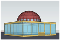 | |||||||||||||
| All façades transparency: 50% | All façades transparency: 25% | All façades transparency: 75% | |||||||||||||
| Samples A–D | Sample E | Sample F | |||||||||||||
 |  | 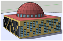 | |||||||||||||
| Variable transparency: 50%–15% | Variable transparency: 25%–15% | All façades transparency 50% with H-V shading elements | |||||||||||||
| Sample G | Sample H | Sample I | |||||||||||||
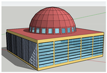 |  |  | |||||||||||||
| All façades transparency 75% with H-V shading elements | All façades transparency 75% with pattern shading elements | All façades transparency 50% with H-V shading elements | |||||||||||||
| Sample J,K | Sample L,M | Sample Optimum Envelope | |||||||||||||
| Variables/Sample Scenarios | A | B | C | D | E | F | G | H | I | J | K | L | M | O.E. | |
| Transparent area | Same on all façades | - | - | - | - | √ | √ | - | - | - | √ | √ | √ | √ | - |
| Variable façade | - | - | - | - | - | - | √ | √ | - | - | - | - | - | - | |
| Heat transfer coefficient | Opaque areas | - | - | √ | √ | - | - | - | - | - | - | - | - | - | √ |
| Transparent A | - | √ | - | √ | - | - | - | - | √ | - | √ | √ | |||
| Shading materials | Horizontal–vertical | - | - | - | - | - | - | - | - | √ | √ | √ | - | - | √ |
| Pattern form | - | - | - | - | - | - | - | - | - | - | - | √ | √ | - | |
| Scenario’s Name | Type | Filling | Glass Layer Types (mm) | Visible Transmittance (%) | Solar Heat Gain Coefficient | U Value (W/m2K) |
|---|---|---|---|---|---|---|
| W1 | Double | Air | 4 + 16 + 4 | 83 | 0.82 | 2.7 |
| W2 | Double | Air | 4 + 16 + 4 | 73 | 0.54 | 1.81 |
| W3 | Double | Argon | 4 + 16 + 4 | 73 | 0.54 | 1.51 |
| W4 | Double | Argon | 4 + 12 + 4 | 73 | 0.54 | 1.46 |
| W5 | Triple | Air | 4 + 12 + 4 + 12 + 4 | 62 | 0.46 | 0.92 |
| W6 | Triple | Argon | 4 + 12 + 4 + 12 + 4 | 62 | 0.46 | 0.78 |
| Thickness Ranges (cm) | U Value (W/m2K) | Energy-Saving in Wall (kWh) | U Value (W/m2K) | Energy-Saving in Roof (kWh) | U Value (W/m2K) | Energy-Saving in Ground (kWh) | ||||||
|---|---|---|---|---|---|---|---|---|---|---|---|---|
| Total Wall | Heating | Cooling | Total Roof | Heating | Cooling | Total Ground | Heating | Cooling | ||||
| 0 | 1.69 | 0 | 0 | 0 | 2.49 | 0 | 0 | 0 | 0.83 | 0 | 0 | 0 |
| 1 | 1.13 | 20,329 | 20,603 | 493 | 1.44 | 65,527 | 65,774 | 1039 | 0.67 | 1227 | 2463 | 1105 |
| 2 | 0.85 | 31,833 | 32,309 | 809 | 1.01 | 93,435 | 93,997 | 1698 | 0.56 | 2030 | 4089 | 1859 |
| 3 | 0.68 | 37,858 | 38,406 | 958 | 0.78 | 109,307 | 110,127 | 2169 | 0.48 | 2357 | 5069 | 2443 |
| 4 | 0.57 | 42,461 | 43,112 | 1114 | 0.63 | 119,008 | 119,960 | 2429 | 0.42 | 2648 | 5814 | 2848 |
| 5 | 0.49 | 45,253 | 45,965 | 1210 | 0.53 | 125,957 | 126,985 | 2598 | 0.37 | 2969 | 326,298 | 36,877 |
| 6 | 0.42 | 46,932 | 47,622 | 1216 | 0.46 | 131,902 | 133,068 | 2812 | 0.34 | 3033 | 326,071 | 37,040 |
| 7 | 0.38 | 48,577 | 49,312 | 1277 | 0.41 | 135,658 | 136,877 | 2914 | 0.31 | 3562 | 7570 | 3615 |
| 8 | 0.34 | 49,946 | 50,702 | 1316 | 0.36 | 138,863 | 140,126 | 3003 | 0.28 | 3385 | 7493 | 3703 |
| 9 | 0.31 | 50,965 | 51,746 | 1352 | 0.33 | 141,281 | 142,605 | 3089 | 0.26 | 3559 | 7798 | 3825 |
| 10 | 0.28 | 52,397 | 53,250 | 1438 | 0.30 | 142,364 | 143,649 | 3072 | 0.24 | 3706 | 8077 | 3944 |
| 11 | 0.26 | 53,098 | 53,973 | 1468 | 0.28 | 145,093 | 146,483 | 3202 | 0.23 | 1961 | 6629 | 4191 |
| 12 | 0.24 | 53,763 | 54,652 | 1490 | 0.25 | 146,624 | 148,029 | 3244 | 0.21 | 2108 | 6859 | 4269 |
| 13 | 0.23 | 54,392 | 55,309 | 1529 | 0.24 | 147,910 | 149,342 | 3282 | 0.20 | 2210 | 7047 | 4346 |
| 14 | 0.21 | 55,009 | 55,929 | 1535 | 0.22 | 149,104 | 150,555 | 3321 | 0.19 | 2246 | 7163 | 4418 |
| 15 | 0.20 | 55,422 | 56,353 | 1551 | 0.21 | 150,131 | 151,610 | 3357 | 0.18 | 4737 | 9557 | 4352 |
| 16 | 0.19 | 55,810 | 56,749 | 1565 | 0.20 | 151,043 | 152,538 | 3388 | 0.17 | 4792 | 9673 | 4407 |
| 17 | 0.18 | 56,151 | 57,095 | 1576 | 0.19 | 151,882 | 153,394 | 3415 | 0.16 | 4828 | 9767 | 4460 |
| 18 | 0.17 | 56,472 | 57,425 | 1587 | 0.18 | 151,616 | 153,062 | 3354 | 0.15 | 4881 | 9870 | 4504 |
| 19 | 0.16 | 56,802 | 57,757 | 1593 | 0.17 | 152,223 | 153,680 | 3374 | 0.15 | 4438 | 9501 | 4573 |
| 20 | 0.15 | 57,029 | 57,987 | 1601 | 0.16 | 152,724 | 154,198 | 3393 | ||||
| Energy Usage | GJ | kWh | Energy Usage | GJ | kWh | Unit Area (W/m2K) |
|---|---|---|---|---|---|---|
| Total side energy | 704.5 | 195,700.0 | Fan | 29.7 | 8255.6 | 217.4 |
| Heating | 429.8 | 119,402.8 | Lighting | 29.8 | 8288.9 | Unit Vol. (W/m3K) |
| Cooling | 184.7 | 51,322.2 | Equipment | 22.6 | 6280.6 | 17.6 |
| Variables | Sample A | Sample B | Sample C | Sample D | Sample E | Sample F | Sample G |
| Transparent Ratio | 50%—all façades | 50%—all façades | 50%—all façades | 50%—all façades | 25%—all façades | 75%—all façades | 50%—3 faç. |
| 15%—North | |||||||
| Overall Heat Transfer Coefficient (W/m2K) | 0.57—wall | 0.57—wall | 0.33—wall | 0.33—wall | 0.57—wall | 0.57—wall | 0.57—wall |
| 0.36—found. | 0.36—found. | 0.25—found. | 0.25—found. | 0.36—found. | 0.36—found. | 0.36—found. | |
| 0.53—roof | 0.53—roof | 0.25—roof | 0.25—roof | 0.53—roof | 0.53—roof | 0.53—roof | |
| 1.8—win. | 0.9—win. | 1.8—win. | 0.9—win. | 1.8—win. | 1.8—win. | 1.8—win. | |
| Shading Materials | None | None | None | None | None | None | None |
| Variables | Sample H | Sample I | Sample J | Sample K | Sample L | Sample M | Opt. Env. |
| Transparent ratio | 25%—3 faç. | 50%—all façades | 75%—all façades | 75%—all façades | 75%—all façades | 75%—all façades | 50%—all façades |
| 15%—North | |||||||
| Overall Heat Transfer Coefficient (W/m2K) | 0.57—wall | 0.57—wall | 0.57—wall | 0.57—wall | 0.57—wall | 0.57—wall | 0.33—wall |
| 0.36—found. | 0.36—found. | 0.36—found. | 0.36—found. | 0.36—found. | 0.36—found. | 0.25—found. | |
| 0.53—roof | 0.53—roof | 0.53—roof | 0.53—roof | 0.53—roof | 0.53—roof | 0.25—roof | |
| 1.8—win. | 1.8—win. | 1.8—win. | 0.9—win. | 1.8—win. | 0.9—win. | 0.9—win. | |
| Shading Materials | None | Horizontal–vertical | Horizontal–vertical | Horizontal–vertical | Pattern form | Pattern form | Horizontal–vertical |
Publisher’s Note: MDPI stays neutral with regard to jurisdictional claims in published maps and institutional affiliations. |
© 2021 by the authors. Licensee MDPI, Basel, Switzerland. This article is an open access article distributed under the terms and conditions of the Creative Commons Attribution (CC BY) license (https://creativecommons.org/licenses/by/4.0/).
Share and Cite
Atmaca, A.B.; Zorer Gedik, G.; Wagner, A. Determination of Optimum Envelope of Religious Buildings in Terms of Thermal Comfort and Energy Consumption: Mosque Cases. Energies 2021, 14, 6597. https://doi.org/10.3390/en14206597
Atmaca AB, Zorer Gedik G, Wagner A. Determination of Optimum Envelope of Religious Buildings in Terms of Thermal Comfort and Energy Consumption: Mosque Cases. Energies. 2021; 14(20):6597. https://doi.org/10.3390/en14206597
Chicago/Turabian StyleAtmaca, Ahmet Bircan, Gülay Zorer Gedik, and Andreas Wagner. 2021. "Determination of Optimum Envelope of Religious Buildings in Terms of Thermal Comfort and Energy Consumption: Mosque Cases" Energies 14, no. 20: 6597. https://doi.org/10.3390/en14206597