Abstract
The micro direct methanol fuel cell (DMFC) has attracted more and more attention in the field of new energy due to its simple structure, easy operation, and eco-friendly byproducts. In a DMFC’s structure, the current collector plays an essential role in collecting the conduction current, and the rational distribution of gas and water. The choice of its material and flow fields would significantly impact the DMFC’s performance. To this end, four different types of cathode current collector were prepared in this study. The materials selected were stainless steel (SS) and foam stainless steel (FSS), with the flow fields of hole-type and grid-type. The performance of the DMFC with different types of cathode current collector was investigated by using polarization curves, electrochemical impedance spectroscopy (EIS), and discharging. The experimental results show that the maximum power density of DMFC of the hole-type FSS cathode current collector is 49.53 mW/cm2 at 70 °C in the methanol solution of 1 mol/L, which is 115.72% higher than that of the SS collector. The maximum power density of the DMFC with the grid-type FSS collector is 22.60 mW/cm2, which is 27.39% higher than that of the SS collector. The total impedance of the DMFC of the FSS collector is significantly lower than that of the DMFC of the SS collector, and the total impedance of the DMFC with the hole-type flow field collector is lower than that of the grid-type flow field. The discharging of DMFC with the hole-type FSS collector reaches its optimal value at 70 °C in the methanol solution of 1 mol/L.
1. Introduction
DMFC is a new type of energy device with the advantages of having a simple structure, easy operation, and emitting low pollution, which is widely used in aerospace, military, and communication fields [1,2,3,4]. The current collector plays an important role by collecting the conduction current and reasonably distributing the gas and water in the DMFC. Researchers have conducted numerous studies on the materials used to fabricate the collector plates and the types of flow fields [5,6,7,8]. It has been found that DMFCs with porous metal collector plates deliver better performance compared to those with conventional stainless-steel collector plates [9,10]. In 2012, Yuan et al. [11] investigated the effects of metal foams, porous metal spikes, metal meshes, and perforated metals on fuel cell performance. In 2014, Wu et al. [12] designed a micro-porous titanium plate-integrated anode structure, and the power density of DMFCs with this new anode structure was up to 40 mW/cm2 at 25 °C. Li et al. [13] prepared a new type of membrane electrode assembly using a stainless-steel fiber mat to replace the collector and liner of the cathode. The experimental results showed that the new structure can significantly reduce the methanol crossover rate, allowing DMFC to operate at higher concentrations of methanol solution, which improves fuel utilization and energy efficiency. In 2017, Ahn et al. [14] investigated the performance of foam metal single cells and stated that the performance of metal foam single cells is almost the same as that of conventional cells at 100% relative humidity and is better than that at 20% relative humidity and pressurization. Xue et al. [15] deposited reduced graphene oxide in stainless-steel fiber mats to prepare the gas diffusion layer and cathode plate. The passive DMFC with this new cathode structure outperformed the conventional DMFC with a peak power density of 23.8 mW/cm2 in 3 mol/L solution at room temperature. It can be deemed that the use of porous metal in the preparation of collector plates for both the anode and cathode could more or less enhance DMFC performance. In 2020, Zuo et al. [16] proposed a direct methanol fuel cell based on a dual-cavity structure and investigated the effect of a stainless-steel metal felt on cell performance. Abraham et al. [17] deposited the Pt and PtRu on a titanium mesh-based electrode and compared it with a conventional carbon-based electrode. The experimental results showed that a Ti anode with an open ratio of 47% and a Ti cathode with an open ratio of 71% is the best combination. Porous metals would be promising in its application.
Moreover, it has been found that different flow field structures and opening ratios have significant effects on DMFC performance [18]. In 2019, Braz et al. [19] investigated the influence of collector plates with opening ratios of 34%, 41%, and 64% on DMFC performance. The experimental results showed that the best DMFC performance was under a collector plate opening ratio of 34%. In 2020, Sharifi et al. [20] used a finite element method (FEM) to build the computational fluid dynamics model of the DMFC flow field plate. The concentration distribution of methanol and oxygen in parallel serpentine channels under optimal operating conditions was studied. Boni et al. [21] studied the influence of perforated collector plates and stainless-steel mesh collector plates on the performance of the passive DMFC, where the experiments of three perforated collector plates and stainless-steel mesh collector plates under different opening ratios were conducted. The results showed that the passive DMFC with a combination of perforated collector plates under an opening ratio of 55.40% and stainless-steel mesh collector plates under an opening ratio of 38.70% achieves the best performance by producing peak power density at a methanol concentration of 5 mol/L. Wang et al. [22] investigated the effects of current collector channel patterns and a current collector open ratio on the performance of DMFC through experiments. The experimental results showed that the DMFC with an open ratio of 45.6% or 35.8% has optimal performance under natural convection conditions. Boni et al. [23] investigated the effect of a collector open ratio on the performance of DMFC, and the experimental results showed that the collector with an open ratio of 55.40% produced MPD at 3M methanol concentration. Thus, selecting the appropriate flow field structure and opening ratio could improve the DMFC performance.
Foam metal has a unique three-dimensional porous structure. It can manage air and water very well with this structure. This feature fits well with the role of the DMFC’s collector. Cathode collectors prepared from foamed stainless steel have better gas–liquid two-phase flow characteristics compared to conventional collectors. Therefore, to improve the DMFC performance, the porous material foam stainless steel (FSS) was used to prepare cathode current collectors with both hole-type and grid-type flow fields. The performances of four different types of cathode current collectors were investigated by analyzing the polarization curves, EIS, and discharging. The remainder of this paper is organized as follows. In Section 2, the structure and experimental conditions of the DMFC are described. In Section 3, the performance of different types of DMFCs is discussed based on experimental results.
2. Materials and Methods
2.1. DMFC Structural Analysis
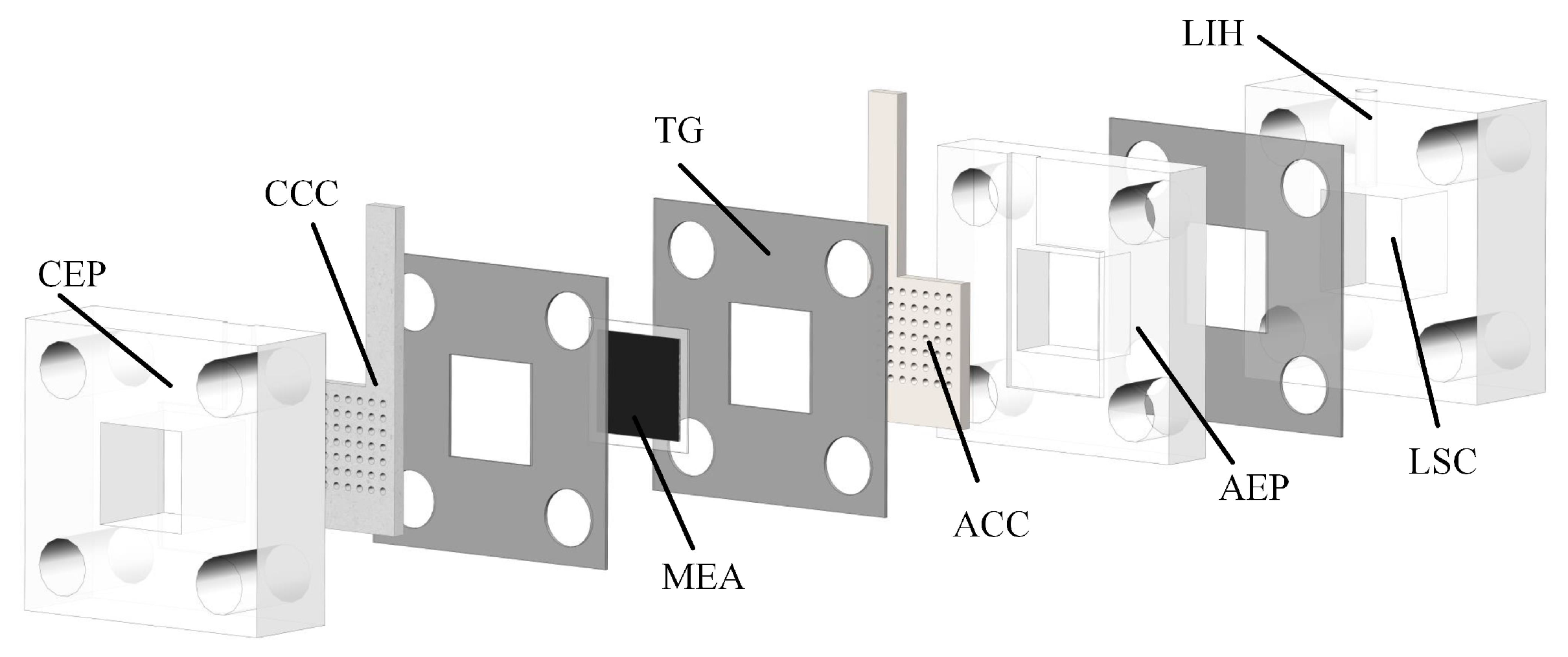
A DMFC generally consists of a cathode current collector (CCC), anode current collector (ACC), membrane electrode assembly (MEA), teflon gaskets (TG), cathode extremity plate (CEP), anode extremity plate (AEP), and liquid storage cavity (LSC) [24,25], as illustrated in Figure 1.
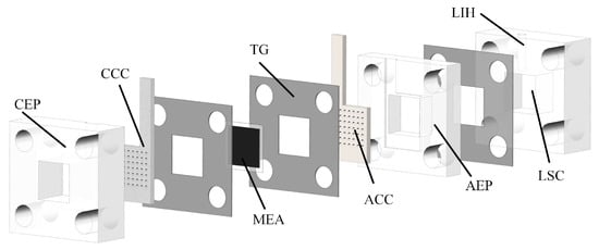
Figure 1.
Decomposition diagram of DMFC.
The CEP, AEP, and LSC are prepared from transparent acrylic sheets. The MEA consists of a gas diffusion layer (GDL), a catalytic layer (CL), and a proton exchange membrane (PEM). The CCC and ACC are pressed against the MEA by two end plates, which are in contact with the GDL to collect the electrons generated on the CL during the operation [26]. The TG is placed between the current collector and the MEA as well as between the LSC and the AEP to reduce the pressure such that the leakage of methanol liquid from the anode side and the reservoir chamber can be prevented. A liquid injection hole (LIH) with a diameter of 3 mm is located above the LSC for liquid injection and CO gas venting. The ACC is connected to the LSC to provide a flow path for methanol. The CCC is in direct contact with the air to feed oxygen to the cathode. It thus plays a role in collecting the conduction current and rationally distributing the cathode reaction water. The selection of the material and flow field of the CCC would significantly impact DMFC performance.
According to recent works [6,27], the best choices of material for the current collector’s preparation are graphite and metal. Studies have shown that graphite current collectors, compared with metal current collectors, have a shortage of low strength, are brittle, and not easy to assemble [28,29]. The foam metal itself has a three-dimensional porous structure which can enlarge the oxygen channels on the cathode side, such that the distribution of oxygen and water can be optimized. Thus, the reaction area on the cathode side and the internal reaction rate can be improved. These make the foam metal current collector a promising candidate for
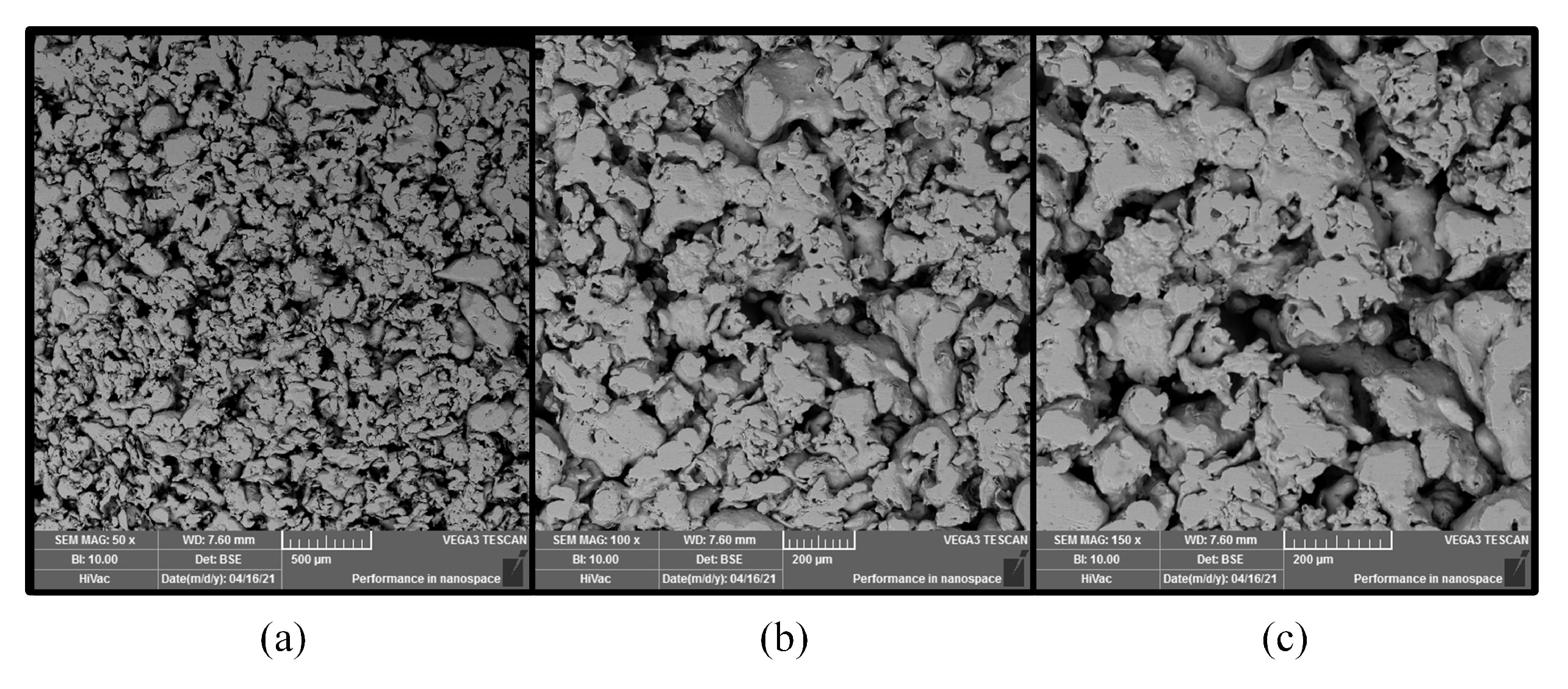
DMFC [12]. In this work, the foam stainless-steel (FSS) CCC with a micro-aperture of 20 m was prepared and compared with stainless-steel (SS) CCC. The SEM images of the FSS structure are shown in Figure 2. The FSS was sintered by using 316 L stainless-steel powder.

Figure 2.
SEM image of stainless-steel foam in different scopes: (a) 50×; (b) 100×; (c) 150×.
The contact angle of the FSS is shown in Figure 3. The water droplets appear suspended because stainless steel is a hydrophobic material. Its contact angle is 95.9°.
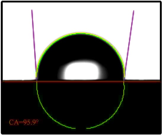
Figure 3.
Contact angle test.
The flow field structure plays an important role in the flow, distribution, and diffusion of reactants and products within the DMFC, where the hole-type and the grid-type are the most used types of structure [6,18]. Both types have an opening ratio of 38.5% and were used in this work to prepare the CCC, as shown in Figure 4.
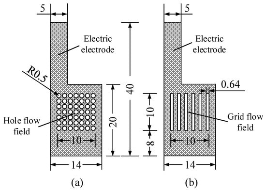
Figure 4.
Flow field structure of the cathode collector in mm: (a) hole type; and (b) grid type.
2.2. DMFC Preparation
The LSC, AEP, and CEP were milled out and cut according to the endplate shape for the TG. They are ultrasonically cleaned with CHOH, CHOH, and deionized water in turn for 15 min to remove the oil from the surface, before being dried in an oven at 100 °C.
For the CCC preparation:
- Porosity of FSS sheets was measured using the water saturation method. The dried FSS sheets were weighed on an electronic balance. Then, these were put into deionized water, ultrasonically saturated for 15 min, and weighed. The porosity of the FSS sheets was calculated from the weight difference. The porosity of the FSS used in this work was 39.8%.
- The FSS sheet with qualified porosity was fixed on a laser cutting platform (Model 6060L-1000W). Cutting speed was set to 4.8 m/min, cutting power was set to 900 W, and cutting frequency was set to 4000 Hz. CCC was obtained by cutting according to the dimensions of the flow field.
- The CCC was placed on a metallographic specimen pre-grinding machine to polish the outer surface to remove the bumps from its surface to ensure that it does not interfere with the DMFC package.
For the MEA preparation:
- The PEM (Nafion 117, DuPont, Wilmington, DE, USA) was flattened by low-temperature hot pressing. Then, it was sequentially placed in 5% wt HO, 0.5 mol/L HSO with an 80 °C water bath for 1 h, and stored in deionized water.
- The CL was prepared by weighing appropriate amounts of carbon powder, Pt and Ru by using an electronic balance (accuracy 0.1 mg). The catalyst loading of the Pt/Ru (50% Pt, 25% Ru) on the anode side was 4mg/cm2, and the catalyst loading of Pt (60% Pt) on the cathode side was 2 mg/cm2.
- The DL on the anode side was made of hydrophilic carbon paper, and hydrophobic carbon paper for the DL on the cathode side.
- The DL, the PEM, and the CL were hot-pressed for 10 min at the temperature of 135 °C and the pressure of 12 MPa to assemble the MEA, whose effective area used in this study was 1 cm × 1 cm.
The DMFC assembled is shown in Figure 5.
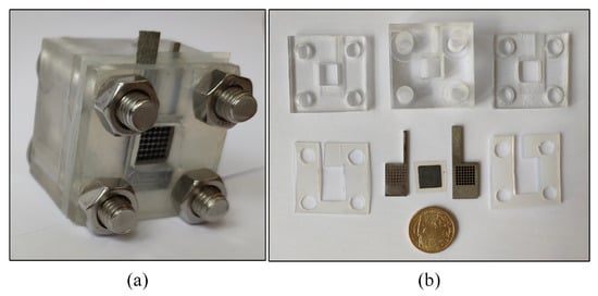
Figure 5.
DMFC: (a) A DMFC cell; and (b) dissembling diagram.
2.3. Experiment Settings
The test platform consists of a DC electronic load (Model IT8511A+), an electrochemical workstation (Model CHI660E), and a thermostat (Model 101-0A), as shown in Figure 6. The voltage–current data were recorded and the EIS was tested. The DMFC was continuously discharged at a current density of 80 mA/cm2 and 70 °C [15,30].
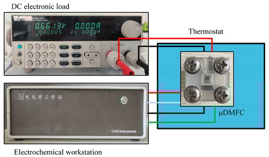
Figure 6.
Test setup for DMFC.
Four different types of DMFC were prepared, namely DMFC for the hole-type stainless-steel cathode current collector (HSS-DMFC); DMFC for the hole-type foam stainless-steel cathode current collector (HFSS-DMFC); DMFC for the grid-type stainless-steel cathode current collector (GSS-DMFC); and DMFC for grid-type foam stainless-steel cathode current collector (GFSS-DMFC). The polarization curves, EIS, and discharge process curves of the four different types of DMFC were separately tested to analyze the performance of the DMFC. DMFC was filled with the methanol solution and placed in a constant temperature chamber.
The I-P-V performance of the DMFC was tested by starting from 0 mA with a 5 mA increment. The data were recorded when the output voltage stabilized for 10 s. Current–voltage and current power density curves were obtained with different methanol concentrations.
When conducting the AC impedance spectrum characteristic test of DMFC, the working electrode and sense electrode were connected to the cathode together, and the reference electrode and auxiliary electrode were connected to the anode with the electronic load. Starting the AC impedance test program, the electronic load was set to a stable discharge state of 80 mA/cm2, the corresponding voltage was fed as the initial voltage, the frequency range of the sinusoidal voltage was set from 100 KHZ to 0.01 HZ, and 5 points of equal frequency band were taken every ten times the frequency changed interval for recording.
3. Results and Discussion
The effect of different methanol concentrations and different types of cathode current collectors on the performance of a DMFC was experimentally investigated at its operating temperature of 70 °C. The polarization, EIS, and discharging curves were analyzed to verify the analytical results of the simulation and material characterization.
3.1. Polarization Curves
To study the performance of different types of DMFC, we tested the power density of DMFCs with four different types of cathode current collectors at 70 °C with different methanol concentrations. Figure 7 shows the polarization curves of the HSS-DMFC, HFSS-DMFC, GSS-DMFC, and the GFSS-DMFC.
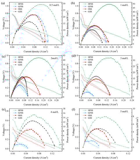
Figure 7.
Polarization curves of DMFC at different methanol solution concentrations: (a) 0.5 mol/L; (b) 1 mol/L; (c) 2 mol/L; (d) 3 mol/L; (e) 4 mol/L; and (f) 5 mol/L. (Hollow markers represent the voltage whereas solid markers represent the power density.)
As can be seen in Figure 7, methanol concentrations of 0.5 mol/L, 1 mol/L, 2 mol/L, 3 mol/L, 4 mol/L and 5 mol/L [31] were used. The maximum current density, the maximum power density, and the operating voltage increase with the FSS were compared to the SS DMFC. The power density of the DMFC sharply decreased at higher current densities. The decrease in power density was mainly due to the fact that the replenishment of the methanol solution at high temperatures does not meet the rate of the electrochemical reaction [32]. When the concentration increased from 0.5 mol/L to 5 mol/L, the power density and current density increased and then decreased because the low concentration of methanol solution cannot meet the electrochemical reaction rate, and the methanol permeation phenomenon will occur when the concentration reaches the value—thus leading to overpotential [33,34,35,36]. The maximum powers of different types of DMFC at different concentrations are shown in Table 1.

Table 1.
Maximum power density of different types of DMFC under different methanol concentrations at 70 °C.
The maximum power density of HSS-DMFC is 22.96 mW/cm2, and the maximum power density of GSS-DMFC is 17.74 mW/cm2. The maximum power density of HFSS-DMFC is 49.53 mW/cm2, and the maximum power density of GFSS-DMFC is 22.60 mW/cm2. Among all the tested samples, the maximum power density is 49.53 mW/cm2 of HFSS-DMFC within 0.5∼5 mol/L methanol concentration. Moreover, the DMFC of a hole-type cathode current collector has a higher current density, power density, and operating voltage than the DMFC of a grid-type cathode current collector with the same material and methanol concentration. The flow channel distribution was more uniform for the same opening rate of the cathode current collector than that of the grid-type cathode current collector, which was more favorable to the collection of electrons by the cathode current collector.
Moreover, the maximum power density of the DMFC was greater with an FSS cathode current collector compared to the one with a SS cathode current collector. The three-dimensional porous structure of the FSS provides more oxygen transfer channels, allowing air to enter the MEA through the micro-pores in the material structure. It thus improves the efficiency of oxygen transfer to the cathode and results in a more uniform reaction zone when the FSS is used as a cathode manifold. The reaction area of the cathode is increased, resulting in a faster reduction reaction rate on the cathode.
3.2. EIS
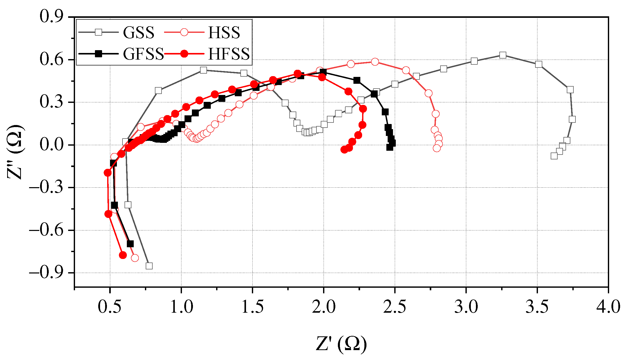
To further investigate the effect on DMFC performance for cathode current collectors of different types, the EIS tests are performed for four types of cathode current collectors at the temperature of 70 °C with the concentration of 1 mol/L [37,38]. Figure 8 shows EIS curves at a discharging current density of 80 mA/cm2 at 70 °C.
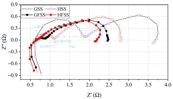
Figure 8.
EIS at a discharging current density of 80 mA/cm2.
In the Nyquist diagram, the right intercept of the real axis represents the transfer resistance of the electrode reaction. The larger the charge transfer resistance (CTR) value, the more severe the polarization during the electrode reaction [32,39]. As can be seen in Figure 8, the right intercept of the Nyquist plot from the real coordinate axis for HFSS-DMFC, GFSS-DMFC, HSS-DMFC, and GSS-DMFC is 2.17 , 2.48 , 2.81 and 3.67 , respectively. Among them, the mass transfer impedance of DMFC with the same material is the same, while there is variability in the charge transfer impedance. The CTR of DMFC with a hole-type flow field is smaller than that of a DMFC with a grid-type flow field.
For DMFC with the same flow filed structure, the DMFC with an FSS cathode current collector has a smaller CRT and a lower charge transfer semicircle at high frequency compared with the DMFC with an SS cathode current collector. In the lower frequency domain, the transfer mass arcs of the FSS-DMFC were smaller than the DMFC of stainless-steel cathode current collector. The transfer impedance of the FSS-DMFC is smaller than the DMFC of stainless-steel cathode current collector. The three-dimensional porous characteristics of the foamed stainless steel allow air from the cathode entering the MEA through micro-pores. This implies that only the flow field part of the stainless-steel current collector transmits oxygen. FSS-DMFC, the micro-pores in the three-dimensional porous structure can provide oxygen access as well.
For DMFC with the same material, the contact impedance of the DMFC of the grid-type cathode current collector is higher than that of the hole-type, while the mass transfer impedance is almost the same. This implies that the oxygen transfer resistance is the same for cathode current collectors with both hole-type and grid-type flow fields. The oxygen channel is only provided by the gas channel. However, the hole-type flow field is uniformly distributed, which facilitates the collection and transmission of the current. The DMFC performance of the hole-type cathode collector can therefore be superior to that of the grid-type.
To investigate the structural effect on the output power of the DMFC, the collector of both hole-type and grid-type flow field structures under operation are simulated by using finite element analysis, as shown in Figure 9.
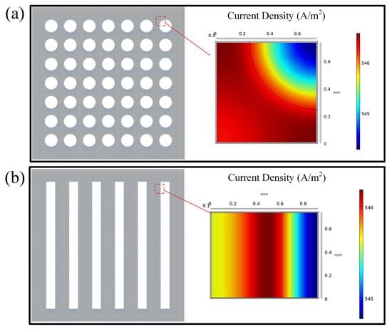
Figure 9.
Current density of aperture type flow field collectors and grid type flow field collectors: (a) Hole-type; (b) Grid-type.
Both the hole-type and the grid-type flow fields have the highest current density at the flow field boundary. The current density is more uniformly distributed in the hole flow field compared to the grid-type flow field. The average current density of the hole-type DMFC is 546.1 A/m2, which is larger than the one of the grid-type 545.7 A/m2. It is mainly due to the fact that the hole-type flow field is more conducive to the collection of electrons in the cathode current collector with the same opening rate.
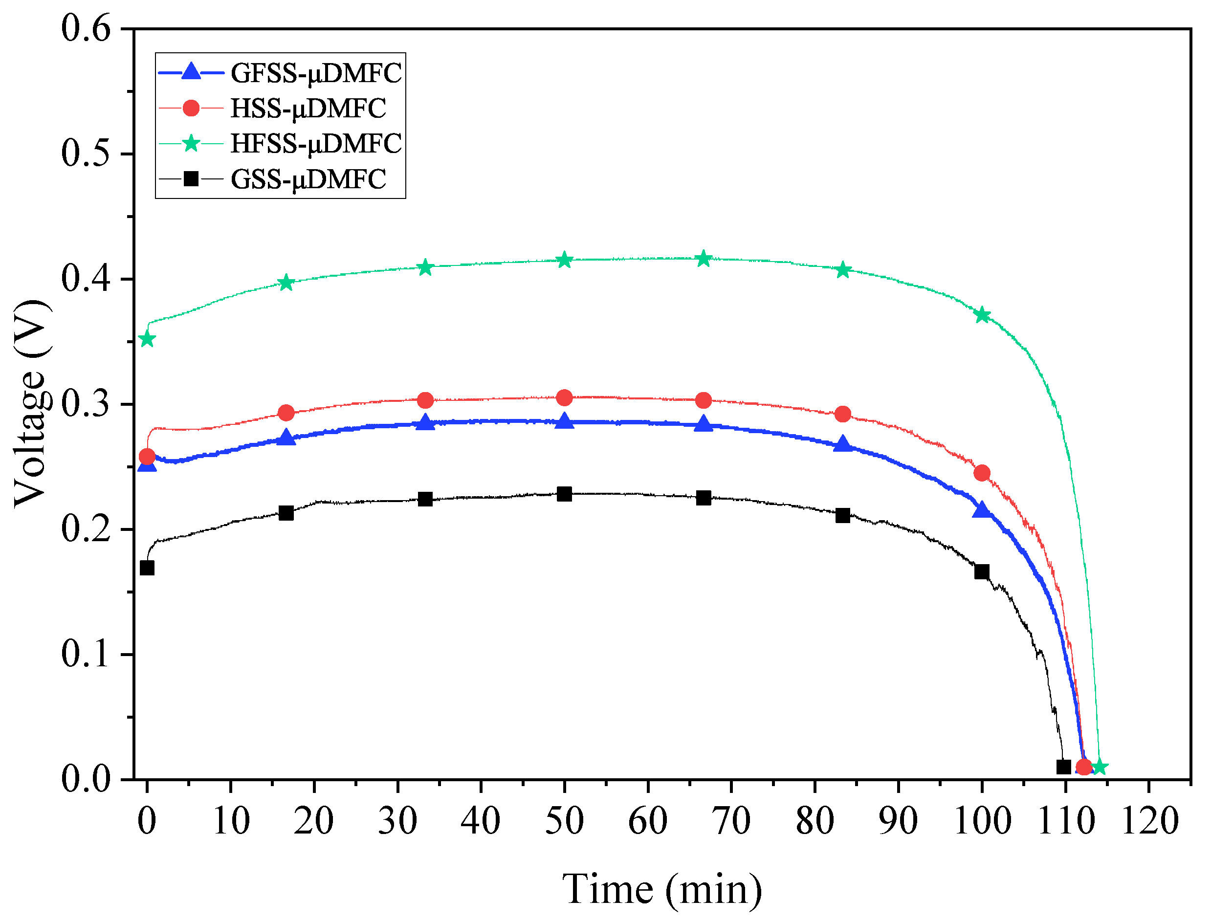
3.3. Discharging
The discharging tests are conducted under a current density of 80 mA/cm2 at 70 °C, and the fuel cell reservoir chambers are filled with 2 mL methanol (1 mol/L). The voltage of different types of DMFC are shown in Figure 10.
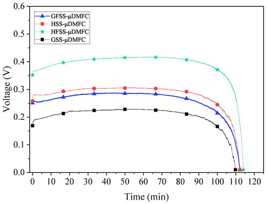
Figure 10.
Discharging curves for different types of DMFC.
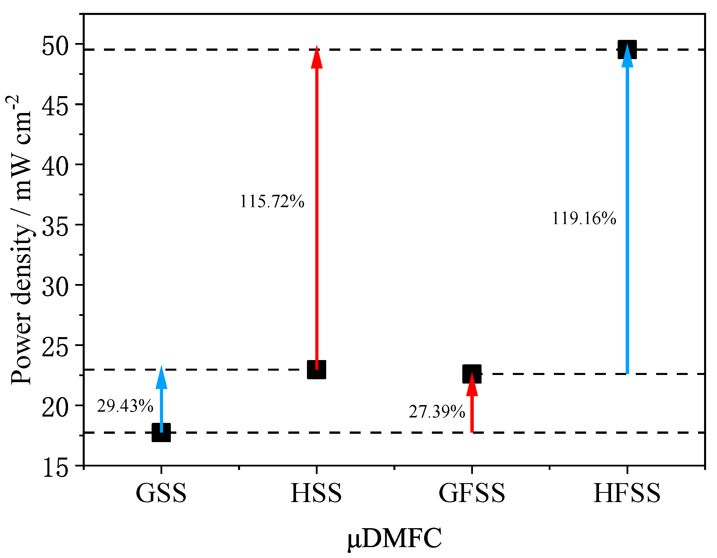
The GSS-DMFC shows the lowest voltage and shortest discharging time, while the HFSS-DMFC gives the highest voltage and longest reaction time during discharging. As discussed in the previous sections, by the unique three-dimensional porous structure of the foam stainless steel, the oxygen transfer pathway to the cathode current collector is increased, and the reaction rate is improved. The total impedance of the DMFC with the FSS collector is smaller than that with the SS collector and its impedance-related power loss is smaller. Moreover, the hole-type cathode collector DMFC delivers higher voltage with longer discharging time. Figure 11 shows the maximum power density for different types of DMFC.
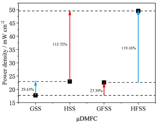
Figure 11.
Maximum power density of different types of DMFC at a 1 mol/L concentration under 70 °C.
As can be seen in Figure 11, the maximum power density of HFSS-DMFC is 49.53 mW/cm2 at 70 °C and 1 mol/L methanol solution concentration, 119.16% higher than that of GFSS-DMFC, and 115.72% higher than that of HSS-DMFC. The maximum power density of GFSS-DMFC is 22.60 mW/cm2 and 27.39% higher than that of GSS-DMFC. The maximum power density of HSS-DMFC is 22.96 mW/cm2, 29.43% higher than that of GSS-DMFC. The foam metal has a high porosity and an interconnected three-dimensional structure, which allows a uniform gas distribution and enhanced gas transfer efficiency. The stability of the discharge of the DMFC with the FSS cathode current collector is better than that of SS. The proposed HFSS-DMFC shows its best performance in terms of output power and stability.
4. Conclusions
In this work, four different types of DMFC were prepared. By investigating the DMFC performance of different cathode current collector types, in terms of flow fields and materials, the evidence showed that:
In terms of the electrode plate material, the maximum power density of HFSS-DMFC is 49.53 mW/cm2 at 70 °C and 1 mol/L methanol solution concentration, 115.72% higher than that of HSS-DMFC. The maximum power density of GFSS-DMFC is 22.60 mW/cm2, 27.39% higher than that of GSS-DMFC. The impedance of the DMFC with the FSS cathode current collector is lower than that of the DMFC with the SS cathode current collector. The stability of the discharging of the DMFC with the FSS cathode current collector is better than that of SS. The foam metal has a high porosity and an interconnected three-dimensional structure, which allows a uniform gas distribution and enhanced gas transfer efficiency. The DMFC performance of the FSS cathode current collector is better than that of the stainless-steel cathode current collector DMFC.
In terms of flow field structure, the maximum power density of the HFSS-DMFC is 49.53 mW/cm2 at 70 °C and 1 mol/L methanol solution concentration, which is 119.16% higher than that of the GFSS-DMFC. The maximum power density of HSS-DMFC is 22.96 mW/cm2, which is 29.43% higher than that of the GSS-DMFC. The performance of the hole-type flow field is better than that of the grid-type flow field with the same opening ratio. The current density distribution of the hole-type flow field is more uniform than that of the grid-type flow field, and the current density values are higher than that of the grid-type flow field. The impedance of the DMFC with the hole-type cathode current collector is lower than that of the DMFC with the grid-type cathode current collector. The proposed HFSS-DMFC shows the best performance in terms of output power and stability.
Author Contributions
Conceptualization, Z.Z. and F.Z.; methodology, Z.Z. and F.Z.; software, F.Z. and Y.Z.; validation, F.Z. and Y.Z.; formal analysis, D.Z.; investigation, F.Z. and Y.Z.; resources, D.Z. and Z.Z.; data curation, F.Z.; writing—original draft preparation, F.Z. and Z.Z.; writing—review and editing, D.Z. and Z.Z.; visualization, D.Z.; supervision, D.Z. and Z.Z.; project administration, D.Z. and Z.Z.; funding acquisition, Z.Z. and D.Z. All authors have read and agreed to the published version of the manuscript.
Funding
This work is partly supported by National Natural Science Foundation of China (grant No.62103174, 62162035) and Yunnan Fundamental Research Projects (grant No.202001AU070046).
Institutional Review Board Statement
Not applicable.
Informed Consent Statement
Not applicable.
Data Availability Statement
Not applicable.
Acknowledgments
The authors would like to thank the editor and the reviewers for their worthy suggestions, time, and effort in improving and finalizing this paper. The authors would further like to thank Li Yingna for providing the support and resources.
Conflicts of Interest
The authors declare no conflict of interest.
Abbreviations
| DMFC | Micro Direct Methanol Fuel Cell |
| SS | Stainless Steel |
| FSS | Foam Stainless Steel |
| EIS | Electrochemical Impedance Spectroscopy |
| CCC | Cathode Current Collector |
| ACC | Anode Current Collector |
| MEA | Membrane Electrode Assembly |
| TG | Teflon Gaskets |
| CEP | Cathode Extremity Plate |
| AEP | Anode Extremity Plate |
| LSC | Liquid Storage Cavity |
| GDL | Gas Diffusion Layer |
| CL | Catalytic Layer |
| PEM | Proton Exchange Membrane |
| LIH | Liquid Injection Hole |
| HSS | Hole-Type Stainless Steel |
| HFSS | Hole-Type Foam Stainless Steel |
| GSS | Grid-Type Stainless Steel |
| GFSS | Grid-Type Foam Stainless Steel |
| CTR | Charge Transfer Resistanc |
References
- Zhao, T.S.; Xu, C.; Chen, R.; Yang, W.W. Mass transport phenomena in direct methanol fuel cells. Prog. Energy Combust. Sci. 2009, 35, 275–292. [Google Scholar] [CrossRef]
- Wei, Y.; Shen, L.; Wang, F.; Yang, W.D.; Zhu, H.; Wang, Z.; Han, K. Synthesis and characterization of novel nanocomposite membrane of sodium titanate/Nafion®. Mater. Lett. 2011, 65, 1684–1687. [Google Scholar] [CrossRef]
- Braz, B.A.; Oliveira, V.B.; Pinto, A.M.F.R. Experimental Evaluation of the Effect of the Anode Diffusion Layer Properties on the Performance of a Passive Direct Methanol Fuel Cell. Energies 2020, 13, 5198. [Google Scholar] [CrossRef]
- Yuan, Z.; Chuai, W.; Guo, Z.; Tu, Z.; Kong, F. The Self-Adaptive Fuel Supply Mechanism in Micro DMFC Based on the Microvalve. Micromachines 2019, 10, 353. [Google Scholar] [CrossRef] [Green Version]
- Hashim, N.; Kamarudin, S.K.; Daud, W.R.W. Design, fabrication and testing of a PMMA-based passive single-cell and a multi-cell stack micro-DMFC. Int. J. Hydrog. Energy 2009, 34, 8263–8269. [Google Scholar] [CrossRef]
- Kundu, A.; Jang, J.H.; Gil, J.H.; Jung, C.R.; Lee, H.R.; Kim, S.H.; Ku, B.; Oh, Y.S. Micro-fuel cells—Current development and applications. J. Power Sources 2007, 170, 67–78. [Google Scholar] [CrossRef]
- Braz, B.A.; Oliveira, V.B.; Pinto, A.M.F.R. Optimization of a passive direct methanol fuel cell with different current collector materials. Energy 2020, 208, 118394. [Google Scholar] [CrossRef]
- Haskul, M.; Ülgen, A.T.; Döner, A. Fabrication and characterization of Ni modified TiO2 electrode as anode material for direct methanol fuel cell. Int. J. Hydrog. Energy 2020, 45, 4860–4874. [Google Scholar] [CrossRef]
- Wang, L.W.; Tian, R.X.; Leng, J.X.; Zhang, Y.F.; Liu, X.W.; Zhou, Z.P. Design and Fabrication of a Polymer-Based Micro Direct Methanol Fuel Cell. Key Eng. Mater. 2011, 483, 616–619. [Google Scholar] [CrossRef]
- Boni, M.; Srinivasa Rao, S.; Naga Srinivasulu, G. Performance evaluation of an air breathing–direct methanol fuel cell with different cathode current collectors with liquid electrolyte layer. Asia-Pac. J. Chem. Eng. 2020, 15, e2465. [Google Scholar] [CrossRef]
- Yuan, W.; Tang, Y.; Yang, X.; Wan, Z. Porous metal materials for polymer electrolyte membrane fuel cells—A review. Appl. Energy 2012, 94, 309–329. [Google Scholar] [CrossRef]
- Wu, H.; Zhang, H.; Chen, P.; Guo, J.; Yuan, T.; Zheng, J.; Yang, H. Integrated anode structure for passive direct methanol fuel cells with neat methanol operation. J. Power Sources 2014, 248, 1264–1269. [Google Scholar] [CrossRef]
- Li, Y.; Zhang, X.; Nie, L.; Zhang, Y.; Liu, X. Stainless steel fiber felt as cathode diffusion backing and current collector for a micro direct methanol fuel cell with low methanol crossover. J. Power Sources 2014, 245, 520–528. [Google Scholar] [CrossRef]
- Ahn, C.Y.; Lim, M.S.; Hwang, W.; Kim, S.; Park, J.E.; Lim, J.; Choi, I.; Cho, Y.H.; Sung, Y.E. Effect of Porous Metal Flow Field in Polymer Electrolyte Membrane Fuel Cell under Pressurized Condition. Fuel Cells 2017, 17, 652–661. [Google Scholar] [CrossRef]
- Xue, R.; Zhang, Y.; Liu, X. A novel cathode gas diffusion layer for water management of passive μ-DMFC. Energy 2017, 139, 535–541. [Google Scholar] [CrossRef]
- Zuo, K.; Yuan, Z. Design and experimental analysis of a dual-cavity high-concentration adaptive passive micro direct methanol fuel cell. Int. J. Energy Res. 2020, 45, 5359–5368. [Google Scholar] [CrossRef]
- Abraham, B.G.; Chetty, R. Design and fabrication of a quick-fit architecture air breathing direct methanol fuel cell. Int. J. Hydrog. Energy 2021, 46, 6845–6856. [Google Scholar] [CrossRef]
- Munjewar, S.S.; Thombre, S.B. Effect of current collector roughness on performance of passive direct methanol fuel cell. Renew. Energy 2019, 138, 272–283. [Google Scholar] [CrossRef]
- Braz, B.A.; Moreira, C.S.; Oliveira, V.B.; Pinto, A.M.F.R. Effect of the current collector design on the performance of a passive direct methanol fuel cell. Electrochim. Acta 2019, 300, 306–315. [Google Scholar] [CrossRef]
- Sharifi, S.; Rahimi, R.; Mohebbi-Kalhori, D.; Colpan, C.O. Coupled computational fluid dynamics-response surface methodology to optimize direct methanol fuel cell performance for greener energy generation. Energy 2020, 198, 117293. [Google Scholar] [CrossRef]
- Boni, M.; Rao, S.S.; Srinivasulu, G.N. Performance evaluation of the incorporation of different wire meshes in between perforated current collectors and membrane electrode assembly on the Passive Direct methanol fuel cell. Chin. J. Chem. Eng. 2021, 32, 360–367. [Google Scholar] [CrossRef]
- Wang, L.; Yin, L.; Yang, W.; Cheng, Y.; Wen, F.; Liu, C.; Dong, L.; Wang, M. Evaluation of structural aspects and operation environments on the performance of passive micro direct methanol fuel cell. Int. J. Hydrog. Energy 2021, 46, 2594–2605. [Google Scholar] [CrossRef]
- Boni, M.; Surapaneni, S.R.; Golagani, N.S.; Manupati, S.K. Experimental investigations on the effect of current collector open ratio on the performance of a passive direct methanol fuel cell with liquid electrolyte layer. Chem. Pap. 2020, 75, 27–38. [Google Scholar] [CrossRef]
- Yuan, Z.; Fu, W.; Zhao, Y.; Li, Z.; Zhang, Y.; Liu, X. Investigation of μDMFC (micro direct methanol fuel cell) with self-adaptive flow rate. Energy 2013, 55, 1152–1158. [Google Scholar] [CrossRef]
- Das, D.S.; Dutta, D.K.; Nessim, G.D.; Kader, M.A.J.D.M.F.C.T. Introduction to Direct Methanol Fuel Cells. In Direct Methanol Fuel Cell Technology; Elsevier: Amsterdam, The Netherlands, 2020; pp. 1–12. (accessed on 1 September 2021). [Google Scholar] [CrossRef]
- Xue, R.; Zhang, Y.; Li, X.; Liu, X. Performance investigation and effect of temperature on a passive μDMFC with stainless steel mesh. Appl. Therm. Eng. 2018, 141, 642–647. [Google Scholar] [CrossRef]
- Ji, S.; Hwang, Y.S.; Park, T.; Lee, Y.H.; Paek, J.Y.; Chang, I.; Lee, M.H.; Cha, S.W. Graphite foil based assembled bipolar plates for polymer electrolyte fuel cells. Int. J. Precis. Eng. Manuf. 2012, 13, 2183–2186. [Google Scholar] [CrossRef]
- May, G.J.J.E. Electronics and Power. In Handbook of Batteries and Fuel Cells; Electronics and Power: New York, NY, USA, 1984; Volume 30, p. 885. [Google Scholar]
- Hz, A.; Jc, B.; Js, A.; Wh, B.J.I.J.o.H.E. Corrosion inhibition of methanol towards stainless steel bipolar plate for direct formic acid fuel cell. ScienceDirect 2020, 45, 30924–30931. [Google Scholar]
- Tomboc, G.M.; Abebe, M.W.; Baye, A.F.; Kim, H. Utilization of the superior properties of highly mesoporous PVP modified NiCo2O4 with accessible 3D nanostructure and flower-like morphology towards electrochemical methanol oxidation reaction. J. Energy Chem. 2019, 29, 136–146. [Google Scholar] [CrossRef]
- Karaoglan, M.U.; Ince, A.C.; Glüsen, A.; Colpan, C.O.; Müller, M.; Stolten, D.; Kuralay, N.S. Comparison of single-cell testing, short-stack testing and mathematical modeling methods for a direct methanol fuel cell. Int. J. Hydrog. Energy 2021, 46, 4844–4856. [Google Scholar] [CrossRef]
- Zhang, Y.; Xue, R.; Zhang, X.; Song, J.; Liu, X. rGO deposited in stainless steel fiber felt as mass transfer barrier layer for μ-DMFC. Energy 2015, 91, 1081–1086. [Google Scholar] [CrossRef]
- Yuan, Z.; Yang, J. The effect of temperature on the output characteristics of micro direct methanol fuel cell. J. Power Sources 2015, 285, 318–324. [Google Scholar] [CrossRef]
- Yuan, W.; Deng, J.; Zhang, Z.; Yang, X.; Tang, Y. Study on operational aspects of a passive direct methanol fuel cell incorporating an anodic methanol barrier. Renew. Energy 2014, 62, 640–648. [Google Scholar] [CrossRef]
- Ye, S.; Feng, J.; Wu, P. Deposition of three-dimensional graphene aerogel on nickel foam as a binder-free supercapacitor electrode. ACS Appl. Mater. Interfaces 2013, 5, 7122–7129. [Google Scholar] [CrossRef] [PubMed]
- Chen, J.; Sheng, K.; Luo, P.; Li, C.; Shi, G. Graphene hydrogels deposited in nickel foams for high-rate electrochemical capacitors. Adv. Mater. 2012, 24, 4569–4573. [Google Scholar] [CrossRef]
- Holze, R. Book Review: Electrochemical Methods. Fundamentals and Applications, 2nd ed.; Bard, A.J., Faulkner, L.R., Eds.; Wiley: Hoboken, NJ, USA, 2002; Volume 41, pp. 655–657. [Google Scholar]
- Chun, D.; Kim, D.; Williamson, Z.R.; Lee, T.; Squibb, C.W. Investigation of fin based oxygen supply modules on the performance of air-breathing polymer electrolyte membrane fuel cells. Appl. Therm. Eng. 2013, 50, 293–301. [Google Scholar] [CrossRef]
- Ben Jadi, S.; El Guerraf, A.; Kiss, A.; El Azrak, A.; Bazzaoui, E.A.; Wang, R.; Martins, J.I.; Bazzaoui, M. Analyses of scanning electrochemical microscopy and electrochemical impedance spectroscopy in direct methanol fuel cells: Permeability resistance and proton conductivity of polyaniline modified membrane. J. Solid State Electrochem. 2020, 24, 1551–1565. [Google Scholar] [CrossRef]


Publisher’s Note: MDPI stays neutral with regard to jurisdictional claims in published maps and institutional affiliations. |
© 2021 by the authors. Licensee MDPI, Basel, Switzerland. This article is an open access article distributed under the terms and conditions of the Creative Commons Attribution (CC BY) license (https://creativecommons.org/licenses/by/4.0/).