Article

The Effect of Hydraulic Diameter on Flow Boiling within Single Rectangular Microchannels and Comparison of Heat Sink Configuration of a Single and Multiple Microchannels

Advanced Engineering Centre, School of Architecture Technology and Engineering, University of Brighton, Lewes Road, Brighton BN2 4GJ, UK
*
Author to whom correspondence should be addressed.
Energies 2021, 14(20), 6641; https://doi.org/10.3390/en14206641
Submission received: 6 September 2021 / Revised: 28 September 2021 / Accepted: 8 October 2021 / Published: 14 October 2021
(This article belongs to the Special Issue CFD Modeling of Two-Phase Flows)

Abstract

:
Phase change heat transfer within microchannels is considered one of the most promising cooling methods for the efficient cooling of high-performance electronic devices. However, there are still fundamental parameters, such as the effect of channel hydraulic diameter D h whose effects on fluid flow and heat transfer characteristics are not clearly defined yet. The objective of the present work is to numerically investigate the first transient flow boiling characteristics from the bubble inception up to the first stages of the flow boiling regime development, in rectangular microchannels of varying hydraulic diameters, utilising an enhanced custom VOF-based solver. The solver accounts for conjugate heat transfer effects, implemented in OpenFOAM and validated in the literature through experimental results and analytical solutions. The numerical study was conducted through two different sets of simulations. In the first set, flow boiling characteristics in four single microchannels of D h = 50, 100, 150, and 200 μ m with constant channel aspect ratio of 0.5 and length of 2.4 mm were examined. Due to the different D h , the applied heat and mass flux values varied between 20 to 200 kW / m 2 and 150 to 2400 kg / m 2 s , respectively. The results of the two-phase simulations were compared with the corresponding initial single-phase stage of the simulations, and an increase of up to 37.4% on the global Nu number N u g l o b was revealed. In the second set of simulations, the effectiveness of having microchannel evaporators of single versus multiple parallel microchannels was investigated by performing and comparing simulations of a single rectangular microchannel with D h of 200 μ m and four-parallel rectangular microchannels, each having a hydraulic diameter D h of 50 μ m . By comparing the local time-averaged thermal resistance along the channels, it is found that the parallel microchannels configuration resulted in a 23.3% decrease in the average thermal resistance R ¯ l compared to the corresponding single-phase simulation stage, while the flow boiling process reduced the R ¯ l by only 5.4% for the single microchannel case. As for the developed flow regimes, churn and slug flow dominated, whereas liquid film evaporation and, for some cases, contact line evaporation were the main contributing flow boiling mechanisms.

1. Introduction

Flow boiling within microchannel heat sinks is considered a promising solution for the effective heat removal of efficient electronics due to the comparatively very high area of heat transfer to volume ratio against conventional channels, as well as the high heat transfer rates and small temperature variations that can be accomplished. The rapid development of micro-electronics and high-power density electronics has resulted in a continuous reduction in the channel size in microchannel evaporators, making heat removal even more challenging for the researchers and designers due to the limited surface area. However, this transition has made necessary the classification between microchannels, minichannels, and conventional tubes. The hydraulic diameter D h constitutes one of the various distinction criteria for this channel classification in the literature. Literature reveals that previous experimental works who tried to identify and differentiate the transition limits between conventional tubes and micro-scale channels, in most cases, disagree in their findings. Some of these studies have concluded that the hydraulic diameter range for microchannels should be between 10 and 200 μ m [1,2] while some other studies state that this range should be between 1 and 1000 μ m [3,4,5]. Such separation is therefore only conventional, and we will conservatively consider only small channels below 200 μm.
In spite of the numerous studies on flow boiling experiments in micro-scale channels that have been conducted up to date, there are only few works focusing on the influence of the hydraulic diameter D h on important parameters such as the heat transfer coefficient, void fraction, as well as the developed two-phase flow regimes. This has resulted in a lack of accurate design correlations, making the effect of D h one of the fundamental unresolved issues for comprehending and predicting the heat transfer and two-phase flow characteristics of flow boiling within microchannels. Even for macro-scale tubes, where more investigations have been conducted compared to microchannels, the widely used physical correlations for the prediction of phase-change heat transfer coefficient consider the effect of the hydraulic diameter not accurately enough [6,7]. In the past years, the effect of D h has been also included in correlations where minichannels are utilised [8,9,10,11,12,13,14]. In the following paragraphs, a review of published investigations is shown, aiming to determine the effect of hydraulic diameter on the heat transfer and two-phase flow characteristics.
Lee and Mudawar [15] performed experiments on subcooled flow boiling of HFE 7100 on microchannels for studying the effects of various parameters, including the influence of hydraulic diameter, on heat transfer performance. The D h of the tested channels was varied between 175.7 and 415.9 μ m at 1 cm length, and the aspect ratio (AR) was between 2.47 and 4.01. From the results, it is evident that the hydraulic diameter and width of the channel can play a complex role in cooling efficiency. Particularly, it has been observed that, under the same operating conditions, when D h is decreased, the wetted area increases, leading to lower heat fluxes along the channel walls, causing a void fraction to decrease along the channels. However, decreasing the channel width continuously, results in bubbles spanning the entire width of the channel, promoting early transition to slug flow.
A series of experimental studies on the effect of D h were also performed by Harirchian and Garimella [16,17,18], using seven different units of parallel microchannels with widths varying between 100 and 5850 μ m , all with a nominal length of 400 μ m . The coolant FC-77 was used throughout the experiments at various mass flux values. In their first work [16], the mass fluxes varied between 250 and 1600 kg / m 2 s . It could be seen that, for a constant applied wall heat flux, the pressure drop was increased when the mass flux was increased, and the channel width was decreased. Additionally, for low mass flux, wall temperatures of the small channels found to be lower, meaning that heat dissipation was increased when the width of the channel was decreased. Additionally, it was found that pressure drop depended strongly on channel size, as well as on mass flux. Finally, flow boiling was found to be governed primarily by nucleate boiling for a low mass flux of 250 kg / m 2 s and all channels 250 μ m , while convective boiling was dominant as the width of the channel and mass flux increased. The results have been compared against various correlations published in the literature for both pool boiling and flow boiling heat transfer. The correlation developed by Cooper [19] for nucleate pool boiling could predict the heat transfer coefficients of the performed experiments for the larger channels with an absolute percentage error of 9%. However, for lower mass fluxes and channels with smaller diameters (e.g., microchannels), this error increased. Subsequently, the same authors [17] conducted another study in order to investigate the channel size (100 to 5000 μ m ) and mass flux effect (225 to 1420 kg / m 2 s ) on the transition of flow regimes. The results revealed that, in total, five two-phase flow patterns (bubbly, slug, churn, wispy-annular, and annular flow) have been observed in the experiments. For the 100 and 250 μ m width microchannels, the flow regimes were similar to each other (slug flow) and different from those of higher widths. Particularly, when the width of the channel is increased, the bubbly slug flow is replaced by a bubbly flow, and an intermittent churn/annular flow pattern is replaced by an intermittent churn/wispy-annular flow. The reason for this transition was investigated in another work by Harirchian and Garimella [18], which indicated that in micro-scale channels, the cross-sectional area is the most influential parameter. Particularly, its modifucation resulted in a change of the governing flow boiling mechanism from the convective boiling heat transfer to nucleate boiling heat transfer for microchannels with area larger than 0.089 mm 2 .
Wang and Sefanie [20] experimentally studied the effect of D h (571, 762, and 1454 μ m on 80 mm heated length) on flow boiling heat transfer within high aspect ratio (W/H) micro/mini-channels. Heat and mass flux values ranged between 0 and 18.6 kW / m 2 and 11.2 to 44.8 kg / m 2 s , respectively, and the coolant used was FC-72. The results showed that heat transfer is influenced negatively when D h is increased, and that the effect is more significant for higher mass flux values. Convective boiling was reported as the dominant boiling mechanism. The results also showed that, when D h is increased, the critical heat flux is increased as well. Using the same channels and under the same experimental conditions as described above (heat and mass flux, FC-72), Wang et al. [21] performed an experimental study on flow boiling in channels of different hydraulic diameter in order to analyse two-phase pressure drop and flow fluctuations through thermographic measurements and visualisation results. From the experiments, fluctuations of low-frequency high-amplitude and high-frequency low-amplitude due to the reverse and re-wetting flow and the vapour slug cluster passage, could be seen. As the heat flux value increases, the low-frequency high-amplitude fluctuation also increased, while the low-frequency oscillation reduced by increasing mass flux. For a given mass flux in microchannels with smaller D h , pressure drop fluctuation amplitudes of low frequencies were influencing heat flux more. Additionally, when q/G was increasing, the average pressure drop increased as well.
An adiabatic two-phase flow experimental study was conducted by Chung and Kawaji [22] on flow characteristics of a nitrogen gas and water mixtures in round microchannels of 530, 250, 100, and 50 μ m diameter with lengths of 277, 157, 64, and 46 mm , respectively. From the experiments, it was observed that microchannels of D h = 250 and 530 μ m had consistent flow regimes with the cases with hydraulic diameter of 1000 μ m (bubbly, slug, churn, slug–annular, and annular flow). For the cases of D h = 50 and 100 μ m , only slug flow could be seen for the investigated flow conditions, and this was related to the significant effects that surface tension and viscosity have on the liquid flow. Additionally, it was shown that when the channel diameter decreases, the multiphase flow frictional multiplier is no longer influenced by the mass flux. Finally, it was concluded that the cross-sectional size of the channel significantly affects the resulting flow regimes, with channel sizes of D h   = 250 and 100 μ m showing the most significant changes on the two-phase flow characteristics, while when D h   < 100 μ m , vividly different two-phase flow characteristics were observed, making the conventional correlations no longer suitable for such gas–liquid pairs. Kawahara et al. [23] further investigated the above research to study the effect of channel cross-sectional size and liquid properties on volume fraction again in isothermal two-phase flows (water/nitrogen gas and ethanol–water/nitrogen gas mixtures) within round channels of D h = 50, 75, 100, and 251 μ m . It has been concluded that the volume fraction changes significantly between channels of D h = 251 and 100 μ m . This is due to the surface tension effects, which play a substantial role as D h is reduced (e.g., <251 µm).
Gunnasegaran et al. [24] performed numerical simulations on single-phase fluid flow characteristics and heat transfer, examining the effect of hydraulic diameter and microchannel shape. The simulations used three full scale microchannel heat sinks, each with different geometrical shapes (rectangular, triangular, and trapezoidal). Each heat sink consisted of 25 parallel microchannels. Heat flux values varied from 100 to 1000 kW / m 2 and were supplied to the solid (aluminium) through a top plate. For each geometrical shape, three cases were examined, each with a different hydraulic diameter, whereas the length was kept constant at L = 10 mm . The height/width ratio was 2.55, 1.53, and 1.03, and D h varied between 148 and 385 μ m . The working fluid was water, and the Reynolds number ranged between 100 and 1000. The simulation results indicated that, for rectangular-shaped microchannel heat sinks, when D h is decreased, the heat transfer is increased. When comparing the geometrical shapes, the rectangular shape microchannels showed the highest heat transfer rate and Poiseuille number, the trapezoidal case was in between, and the triangular shape had the lowest performance. Additionally, as expected, it was indicated that when the Re number is increased, the value of the heat transfer coefficient is increased as well. Sahar et al. [25] also numerically studied the effect of D h and aspect ratio on single-phase flow heat transfer in a single rectangular micro-passage using ANSYS Fluent 14.5. Two sets of simulations were performed. In the first case, hydraulic diameters ranged between 100–1000 μ m , and the AR remained constant at 1. Subsequently, the AR ranged between 0.39 and 10, and the hydraulic diameter remained unchanged at 560 μ m . The working fluid was water, and the Re numbers varied between 100 and 2000. Constant heat-flux was applied at the bottom and the two side walls of the channel, whereas the top wall was considered adiabatic. Conjugate effects were ignored. The numerical results demonstrated that the average Nusselt number and friction factor increases when D h is increased as well. Additionally, it was found that the effect of hydraulic diameter on heat transfer and friction factor is more influential than the effect of aspect ratio. Another numerical investigation on the channel confinement and hydraulic diameter effect on the single-phase fluid flow heat transfer on rectangular channels using ANSYS Fluent 15 was performed by Sathishkumar and Jayavel [26]. The hydraulic diameters ranged between 100 and 1000 μ m (keeping constant AR = 1 and L = 62 mm ) with Re numbers of 500 and 1500. The constant heat flux boundary condition was prescribed at the bottom and the two side walls, whereas the top wall was considered adiabatic, with a uniform inlet velocity condition being imposed at the inlet of the channel, and zero pressure was imposed to the exit of the channel. The channels consisted of a constant mesh size of 20 × 15 × 400 cells. Based on the simulation results, it is concluded that the heat transfer is significantly affected by the variation of D h and channel confinement, and that with the increase in D h , the Nusselt number value increases for both Re cases.
Apart from studying the effect of channel diameter, more recent investigations have focused on the influence of the number of parallel microchannels, aiming to provide answers on whether the increase in the total number of microchannels could lead to a higher heat transfer performance [27,28]. The influence of number of parallel micro-passages on flow boiling heat transfer of water has been studied both experimentally and numerically in the past by Hedau et al. [29]. The applied heat flux values ranged between 230 and 2200 k W / m 2 and mass flux between 250 and 500 kg / m 2 s . For the numerical part, the VOF solver of ANSYS Fluent 16.0 has been employed, and the phase change model developed by Lee was utilised for the mass transfer process of evaporation [30]. The considered heat sinks included 6, 10, and 14 parallel microchannels for a D h of 810, 590, and 384 μ m , respectively. From the results, it was concluded that, for a high number of channels, a greater heat transfer coefficient is achieved. Specifically, the HTC for the 14 channels case and applied heat flux of 2200 k W / m 2 was found to be increased by 240% compared to the case with the six channels for the same flow conditions. This was attributed to the low thickness of the film evaporation throughout the annular flow regime due to the increased available surface to volume ratio as compared to the case with six microchannels. More recently, Dai et al. [31] conducted a numerical investigation on the effect of various parameters such as porosity, channel thickness, height, material, and channel number on flow boiling characteristics, using a microencapsulated phase change material slurry as the working fluid. A heat flux of 1000 kW / m 2 was applied at the bottom side of the heat sink, whereas the inlet velocity was 2 m / s . The commercial CFD software ANSYS Fluent 17.0 was utilised, with a grid size of approximately 800 K cells. The thermal resistance between multi-channel heat sinks, consisting of 30, 40, 50, 60, 70, and 80 channels, was measured, and it was found that, as the microchannel number increased, thermal resistance increased as well, attributing this to the reduction in copper vertical rib thickness, which was not kept constant for this investigation.
It is therefore evident that, despite the fact that the effect of microchannel hydraulic diameter has been widely studied, providing valuable information so far on the heat transfer and flow characteristics, the majority of these investigations also alter other important parameters, such as the aspect ratio and the geometrical shape of the cross-section, resulting in contradicting conclusions. Furthermore, the majority of these cases focus on results after a steady state condition has been achieved in the system, ignoring the early stages of the fluid flow characteristics and heat transfer. Finally, the majority of the numerical works are focusing either on single-phase flow phenomena or ignore the conjugate heat transfer effects.
For this reason, the objective of the present work is to investigate the effect of channel hydraulic diameter on flow boiling heat transfer on the first transient stages of flow pattern development and heat transfer characteristics by performing numerical simulations where the channel hydraulic diameter will be varied and all other flow and channel design parameters will remain unchanged, thus isolating the investigated effect. This also constitutes the key novelty of the present work. As the exact isolation of the hydraulic diameter without affecting other important flow and heat transfer characteristics, also taking into account the conjugate heat transfer effects, is numerically examined for the first time in the literature. For a better understanding of the phenomena, different values of heat and mass flux have been considered, with a detailed qualitative and quantitative comparison of the numerical predictions. Additionally, in the present work, a comparison between a single microchannel and four parallel microchannels, of the same total hydraulic diameter, is also conducted. In this case, to isolate the investigated effect, the total volumetric flow rate for both cases remain constant, while the flow rate passing from each of the four parallel channels is reduced by a factor of four, accordingly.

2. Numerical Method

2.1. Governing Equations

The open-source CFD toolbox OpenFOAM and a custom, enhanced VOF-based solver has been used for the performance of the simulations presented in this study. The improvements of the solver involve a treatment for spurious velocities dampening, an enhanced dynamic contact angle treatment model, and a phase-change model in the fluid domain, also considering conjugate heat transfer effects with a solid domain.
The equations for mass, momentum, and energy conservation as well as the volume fraction are presented below. In this work, it is assumed that the vapor and liquid phases are incompressible Newtonian fluids. The utilised solver has been extensively validated against experiments and analytical solutions available in the literature, and it has been shown that it can be safely used in investigations involving diabatic and adiabatic flow boiling. For more details, the reader is referred to [32,33,34,35,36].
The mass conservation equation is given as:
· ρ U = ρ · ,
where U is the fluid velocity vector, and ρ is the bulk density. The source term on the right-hand side accounts for the phase change. The momentum conservation can be calculated as follows:
t ρ U + · ρ U U · μ U + U T = p + f ST + f g ,
where p is the pressure, and μ is the bulk dynamic viscosity. The momentum source terms on the right-hand side of the equation account for the effects of surface tension and gravity, respectively. In the numerical model, the approach based on the work of Brackbill et al. [37] is used for the calculation of the surface tension. The conservation of energy equation is written as:
t ρ c p T + · U ρ c p T · λ T = h · ,
where c p , T , and λ are the bulk heat capacity, temperature, and bulk thermal conductivity, respectively. The source term on the right-hand side of the equation represents the contribution of the enthalpy of evaporation/condensation or else the cooling/heating associated with the latent heat of the phase-change. Equation (4) shows how the advection of the volume fraction by the flow field is conducted:
α t + · α U · α 1 α U r = ρ · ρ α
The sharpening of the interface is important when two-phase flow of two immiscible fluids is simulated. The interface sharpening in OpenFOAM is artificially achieved by adding the additional compression term · α 1 α U r in Equation (4). Here, the artificial compression velocity is denoted as U r . The right-hand side source-term of Equation (4) is needed due to the local mass source terms, and the velocity field is not free of divergence. Additionally, the bulk fluid properties γ are calculated as the averages over the liquid (γl) and vapour (γv) phases, weighted with the volume fraction α, i.e., γ=αγl+(1 − α)γv. As stated earlier, the VOF-based solver that is used in this study has been modified accordingly in order to account for an adequate level of spurious currents suppression. The reader is referred to [32], for a detailed presentation of the model.
The conservation of energy equation in the solid domains is defined as:
t ρ s c p s T = · λ s T ,
where ρ s is the density of the solid, and c p s is the heat capacity.
The interface coupling of the solid and fluid region is achieved iteratively under the following conditions:
T f = T s ,     λ f T f n = λ s T s n ,
where T f and T s are the temperature at the fluid side and solid side of the conjugate heat transfer boundary, respectively, whereas λ f and λ s are the thermal conductivity of the fluid and solid domain, respectively.

2.2. Phase Change Model

In the process proposed by Hardt and Wondra [38], the evaporating mass is deducted from the liquid side of the interface and appears again on the vapour side. The mass flux at the interface of the two phases ( j e v a p ), which is derived from evaporation/condensation, is found by the following expression:
j e v a p = T i n t T s a t R i n t h l v ,
where T i n t is the interface temperature, T s a t is the saturation temperature, R i n t is the interfacial heat resistance, and hlv is the latent heat of evaporation at the saturation temperature. The quantity of the evaporated liquid is calculated locally, and the resulting source term field is smeared over a few cells in order to prevent numerical instabilities.
The interfacial heat resistance is expressed as:
R i n t = 2 γ γ 2 π R g a s h l v 2 T s a t 3 / 2 ρ ν
The above equation represents a fitting function. This is proved by the varying uncertainty of the γ parameter, contained within the range 0 < γ < 1. In this case, the parameter γ, which can be referred to as the evaporation/condensation coefficient is equal to 1. The term R g a s represents the specific gas constant of the fluid, which is calculated by R/M, where R is the universal gas constant, and M is the molar mass of the fluid.
The mass flux from evaporation and condensation, calculated from Equation (8), is added to the conservation equations, from the definition of an appropriate volumetric source term. The volumetric source term is found by multiplying the flux of evaporated mass at the interface by the magnitude of the volume fraction gradient. This definition is explicit in the equation below:
ρ · 0 = j e v a p α
Integrating this initial source term field through the entire interface in the computational domain is enough for calculating the “Net Mass Flow”. To do this, the following equation was used:
m · int = ρ · 0 d V
The “Net Mass Flow” is very relevant to guarantee mass conservation in the domain. The mass source magnitudes of liquid and vapour should be equal, as they represent the net evaporation rate.
In order to avoid computational instabilities, the initially calculated sharp source term is smeared over a finite number of computational cells. This is performed through the solution of a diffusion equation for the smooth distribution of source terms. This is shown below:
ρ · 1 · D Δ τ ρ · 1 = ρ · 0
An artificial time step Δ τ is utilised for this purpose, and Neumann boundary conditions are applied in all boundaries of the domain for the smeared source term ρ · 1 . Although this is artificial smearing of the original source term, the integral values of the sharp and the smooth fields remain the same. The overall width of the smeared field is proportional to the square root of diffusion constant “D” times the artificial time step “ Δ τ ”. The chosen value of “D” must be, in each case, adjusted to the mesh resolution to ensure smearing over a finite number of cells.
Subsequently, in order to continue avoiding computational instabilities, the source terms in all cells that do not contain pure liquid or vapour (α < 1 − α c u t and α > α c u t , where α c u t is set to 0.001) should artificially be set to zero. The interface cells are not subjected any more to source terms after performing the last step. Hence, the interface is only transported by the calculated velocity field. This secures that the transport algorithm for the α field and the associated interface compression (described previously) can work efficiently without any interference with the evaporation/condensation source term field. However, for maintaining continuity, the remaining source term field needs to be scaled accordingly, at the liquid and the vapour side through the use of scaling coefficients. This final scaling step secures that the mass is globally conserved. The proposed scaling coefficients N l and N v are, in effect, the ratio of net mass flow m · i n t to the volume integrals (over the entire computational domain) of the smooth source term field in each of the pure phases:
N l = m · int a 1 + a c u t ρ · 1 d V 1
N v = m · int a c u t a ρ · 1 d V 1
After performing this scaling, the final source term field is calculated using the expression (14):
ρ · = N v · ( α c u t α ) ρ · 1 N l α 1 + α c u t ρ · 1 .

2.3. Dynamic Contact Angle Treatment

The dynamic contact angle model proposed by Kistler [39] is included in the solver that is used in this study. This model has been validated in the past against adiabatic and diabatic experiments, showing better accuracy compared to other contact angle models. Detailed information about the implementation of the model can be found in [35].

2.4. Heat and Mass Transfer

For the calculation of the parameters including dimensional and non-dimensional numbers, which are presented in the results section, the following expressions have been used.
The mass flux is referred as G and defined as
G = V ·   ρ l n A c ,
where ρ l is the liquid density, n is the number of the microchannels, A c is the cross-sectional area, and V ·   is the volumetric flow that can be found by
V · = U l   A C
The heat flux is defined as follows:
q = h T w a l l T s a t .
From Equation (17), the heat transfer rate can be easily found by
Q = q   A H A ,
where A H A is the heated area of the solid wall perpendicular to the heat flux direction.
For the calculation of the local Nusselt number, the local time-averaged heat transfer coefficient h(x,t) needs to be calculated from the following expression:
h x , t = q T w x , t T s a t ,
where x is the position along the central longitudinal axis of the conjugate heat transfer boundary, q is the applied heat flux in W/m2 at the bottom surface of the solid domain, T w x is the temperature along the central longitudinal axis of the conjugate heat transfer boundary, and T s a t is the saturation temperature.
The time-averaged local Nu number is then calculated from the following relationship:
N u t ,   a v g x = h ¯ x D h λ l     ,
where λ l is the liquid thermal conductivity, and D h is the hydraulic diameter of the channel, which can be calculated from the following relationship:
D h = 2 W   H W + H ,
where W is the width and H is the height of the channel.
The global averaged Nusselt number ( N u g l o b ) represents the area below the resulting local time-averaged Nut, avg over dimensionless length L* curve and is calculated as follows:
N u g l o b = i = j n N u j , n / L *
In order to evaluate the heat transfer performance of the multiple microchannel case and to compare it with the single channel case, both the global, R g l o b , and local time-averaged thermal resistance, R ¯ l , are used:
R g l o b = i = j n R j , n / L * ,
where
R ¯ l = ( T ¯ w a l l T s a t ) /   A H A   q
A H A is the heated area of the entire heat sink, perpendicular to the heat flux direction.

3. Application of the Numerical Model

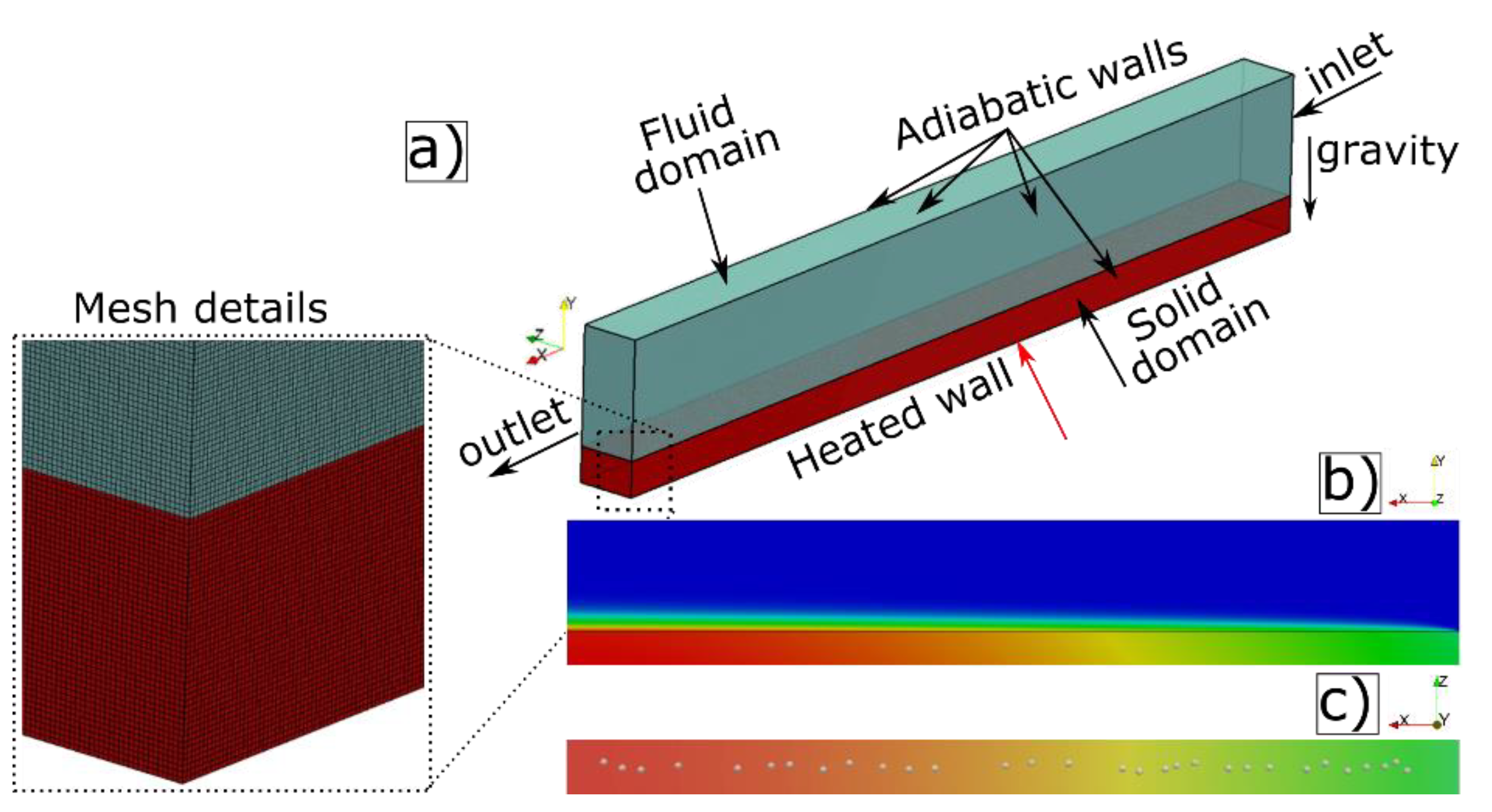
3.1. Computational Geometry and Boundary Conditions

In order to be able to account for conjugate effects, the 3D computational grid has been discretised in a solid and a fluid domain, each of them consisting of uniform, structured, hexahedral elements. The shape of the tested microchannels is rectangular, and the aspect ratio (AR =   W / H ) is set to 0.5 for all the cases. The examined hydraulic diameters D h are 50, 100, 150, and 200 μ m , and the length of the channels is 2.4 mm . Information about the dimensions of the utilised microchannels is shown in Table 1.
A constant heat flux q″ boundary condition is applied at the bottom wall of the solid domain, whereas the other walls of the channels are considered adiabatic. Since the model accounts for conjugate effects, a temperature and heat flux coupling boundary condition is used at the interface of the upper wall of the solid domain and the bottom wall of the fluid domain. A constant velocity boundary condition is applied in the inlet of the fluid domain, and fixed pressure is applied at the outlet. Finally, the volume fraction value was assigned as unity, as saturated liquid only enters from the inlet during the calculations. Detailed description of the boundary conditions can be found in [40].

3.2. Numerical Simulation Set-Up and Process

Figure 1a shows the computational domain, boundary conditions, and mesh details for the present numerical investigation. The simulations consist of two different stages. In the first stage, saturated liquid enters the microchannel, flowing with a specified constant mass flow rate (for all the considered cases, the flow is maintained in the laminar regime). This stage is run up for a few seconds of real flow for all cases presented in this work, aiming to a steady state where the hydrodynamic and thermal boundary layers are fully developed. The fully developed thermal boundary layer is shown in Figure 1b. After that, the second stage is initiated, which leads to the main focus of the present paper, where thirty vapour nuclei (bubble seeds), represented as a half-sphere with a radius of 10 μ m , are patched onto the conjugate heat transfer boundary (interface between the fluid and solid domains) arbitrarily distributed along the channel, as illustrated in Figure 1c. Artificially placing these bubble seeds at this step is necessary to initiate the flow boiling process, since the present model does not account for the boiling inception through the application of existing empirical bubble nucleation sub-models. Since these patched bubble seeds are positioned within a developed thermal boundary layer, where the temperature is greater compared to the saturation temperature T s a t , boiling occurs at the solid/liquid/vapour triple line as well as at the parts of the liquid/vapour interface that is in contact with temperatures greater than T s a t . The working fluid for all the examined cases is ethanol, and the properties used in the setup of the cases are obtained as those of ethanol liquid and vapour at T s a t = 351.05 K at a pressure of 1 bar from [41]. With regard to the solid domain, the properties of stainless steel have been considered for all cases. The physical properties of the ethanol and stainless steel are shown in Table 2 and Table 3, respectively. Finally, the advancing and receding contact angles are 19° and 8°, respectively, for all the simulations. For isolating the exact effect of the microchannel hydraulic diameter, all the fluid and solid properties, as well as the total applied heat transfer rate Q (in W), together with the volumetric flow rate V · (in m 3 / s ), are kept constant. To keep Q and V · values constant, since the hydraulic diameter of each microchannel varies, the applied heat flux q , velocity of the fluid flow U l , and hence the mass flux G (see Equation (16)) vary accordingly with respect to the hydraulic diameter variation.
In order to be able to better understand the phenomena, under different conditions, each of the considered hydraulic diameters are tested for two different values of applied heat flux q″ keeping the heat transfer rate constant at values of Q = 7.20 × 10 3 W and 1.80 × 10 2 W, respectively. The above selected conditions for the simulations are selected to be similar to those reported in experimental investigations of saturated flow boiling within microchannels available in the literature, e.g., [42]. The overall operating conditions considered for the numerical experiments are summarised in Table 4.
In order to have a more realistic case scenario, after the initial nucleation of the thirty bubbles at t = 0 ms , multiple recurring nucleation events of thirty bubbles with constant nucleation frequency of every 0.4 ms and at the same nucleation position, as shown in Figure 1c, have been chosen for the presented simulations. Hence, each nucleation cycle lasts for 0.4 ms , and a total of 10 nucleation cycles are considered (10 × 0.4 ms = 4.0 ms ) for all of the considered D h , heat, and mass fluxes. For the performance of the 3D, transient numerical simulations, a high-performance computing (HPC) cluster has been utilised, and more than 800,000 core-hours were needed for the overall runs of the present paper. The Courant number kept constant at 0.5, whereas the calculation time step was varied automatically ranging from 10−8 up to 10−6 s.
At this point, it should be mentioned that the selected mesh size of the present simulations has been chosen after performing a mesh independence study in order to ensure that the solution is not influenced by the size of the mesh in a previous work by the same authors [40], where the effect of wettability was investigated for the 200 μm channel that is also used in the present investigation.

4. Numerical Simulation Results

4.1. Effect of Hydraulic Diameter for a Single Microchannel

The results from the simulations examining the effect of hydraulic diameter considering a single rectangular microchannel are presented in the following paragraphs. Initially, the cases with constant q = 7.20 × 10 3 W and varying heat fluxes (20, 26.7, 40, and 80 kW / m 2 ) and constant volumetric flow rate of V · = 9.1611 × 10 9 m 3 / s with varying mass fluxes (150, 267, 600, 2400 kg / m 2 ), which correspond to hydraulic diameters of 200, 150, 100, and 50 μ m , respectively, will be presented. In Figure 2, qualitative/macroscopic flow visualisation results of the spatial and temporal evolution of the generated vapour bubbles for all the examined hydraulic diameters are illustrated. A top view and a 3D isometric view are shown for four successive time instants in each case. Overall, from a first analysis of the qualitative data, it can be inferred that the effect of the D h of the channel exerts a significant influence on the resulting two-phase flow regimes, with the diameter of a 100 μ m to be considered as a flow regime transition threshold. For all cases, the initialised bubble seeds on the heated wall grow and merge together, forming large, elongated bubbles, which are transferred downstream by the liquid cross-flow. For the cases of 50 μ m and 100 μ m , after each nucleation cycle, the detachment of the bubbles occurs rapidly, resulting into a churn flow for the former case and into an initially churn flow, during the early time instants (e.g., within the first millisecond), which is quickly transitioned into a slug flow for the 100 μ m case. On the other hand, for the other two cases, bubble detachment lasts a few fractions of a millisecond more, leading to a direct slug flow regime. By observing both top and 3D views of the macroscopic results, it can be seen that, for all cases, there is no contact between the adiabatic top wall and the generated bubbles, whereas a contact between some of the bubbles with the two adiabatic sidewalls can be seen for all the cases, for at least one of the shown time instants. However, it is clear that the generated bubbles for the case of 100 μ m have the least contact with the three adiabatic walls of the microchannel, meaning that no formation of dry patches is seen in these regions in this particular case. This may be attributed to the comparatively thicker liquid film surrounding the vapour slugs compared to the cases with higher hydraulic diameter. With regard to the shape of the vapour bubbles, after detaching from the surface and the leading edge approaches the outlet of the channel, a characteristic symmetric bullet shape nose is observed for all cases. The curvature of the nose increases as the hydraulic diameter decreases, leading to an increment of the evaporation liquid film thickness. Overall, liquid film evaporation is the main heat transfer mechanism for all cases. For the cases of 150 μ m and 200 μ m , the primary heat transfer mechanism during the early stages of the vapour bubbles growth (e.g., 0.5 ms ) is the contact line (meniscus) evaporation due to the delayed detachment of the bubbles from the heated surface. However, for the later time instants, the already generated elongated vapour slugs have detached from the heated surface, making liquid film evaporation the main heat transfer mechanism.
During the second set of simulations, the heat transfer rate for all the cases is increased to Q = 1.80 × 10 2 W by varying the corresponding applied heat fluxes to 50, 66.7, 100, and 200 kW / m 2   for each of the considered channel hydraulic diameters. The volumetric flow rate and mass flux have remained unchanged compared to the previous set of simulations, with the values being V · = 9.1611 × 10 9 m 3 / s and G = 150, 267, 600, and 2400   kg / m 2 s for the cases of D h = 200, 150, 100, and 50 μ m , respectively. Figure 3 shows the qualitative numerical results for four common time instants. With regard to the flow characteristics, it is indicated that the increase in heat flux has resulted in an increased bubble growth rate; hence, more elongated bubbles for the cases of 100, 150, and 200 μ m can be observed, whereas for the 50 μ m microchannel, no significant differences compared to the corresponding D h case of Figure 2 can be observed. Churn flow appears to be the two-phase flow regime for the cases of 50 and 100 μ m ; however, a transition into slug flow is also observed for some cases. Similar to the previous set of simulations, the scaling down of D h increases the curvature of the nose of the bubble(s) and hence the thickness of the liquid film. Finally, contact line evaporation can be considered as the main heat transfer mechanism during the very early stages of the evaporation process (e.g., 0.5 ms ) for the cases of 200, 150, and 100 μ m ; however, for later time instants, the main heat transfer mechanism is liquid film evaporation. For the 50 μ m case, the main heat transfer mechanism is liquid film evaporation.
A quantitative comparison of these cases is conducted in Figure 4 and Figure 5. In Figure 4, the dimensionless time-averaged local Nusselt number N u ¯ x over the dimensionless length of the channel L* for all of the examined hydraulic diameter, heat, and mass flux combinations, together with their reference single-phase stage, is plotted. Subsequently, the percentage difference of the global Nusselt number ( N u g l o b ) between the two-phase simulations compared to the corresponding single-phase is shown in Table 5.
At first glance, examining the resulting curves on Figure 4, it is clear that the increase in D h implies a linear increase in the overall N u ¯ x for both of the considered applied heat transfer rates for the single and two-phase simulations. Additionally, a negligible effect of the increase in the applied heat rate is observed in the single-phase curves for all cases as well as in the two-phase curves for some of the considered hydraulic diameters. In Figure 5, the percentage difference between the single-phase and the corresponding two-phase simulation of the local time-averaged heat transfer coefficient ( Δ h ¯ x = h ¯ x t p h ¯ x s p h ¯ x s p × 100 ) versus the L* is plotted for both examined heat transfer rates Q . It is clear from this figure that the heat transfer coefficient variation is much smoother for the case of D h = 50 μ m compared to the case of 200 μ m . Additionally, it is also clear that the case of 50 μ m shows the greatest increase in h ¯ x , followed by the case of 100 μ m and the cases of 200 μ m and 150 μ m , respectively. This is also evident by observing, where for Q = 7.20 × 10 3 W , the N u g l o b for the 50 μ m two-phase case has been increased by 37.4%, compared to the corresponding single-phase simulation, and that for the 100 μ m case has been increased 25.9%, whereas for the 150 and 200 μ m cases, N u g l o b has been increased by 22.2% for both cases. The increase in the heat transfer rate to Q = 1.80 × 10 2 W seems not to have positively or negatively affected the heat transfer performance of the 50 μ m channel, while for the other cases, a further increase in the N u g l o b is observed.
Based upon the qualitative and quantitative results of the simulations presented so far, the following noteworthy conclusions can be drawn.
  • Smaller elongated bubbles/slugs are observed when the hydraulic diameter is increased.
  • The increase in heat transfer rate Q has resulted in an increase in bubble growth rate and bubble coalescence, resulting in more elongated vapour slugs.
  • The bubbles grow to occupy the entire cross-section with elongated or intermittent vapour slugs within few fractions of a millisecond.
  • For the case of Q = 7.20 × 10 3 W, dry patches are formed only on the adiabatic side walls of the microchannel and mainly for the cases of hydraulic diameter D h = 200 and 150 μ m . For the case of Q = 1.80 × 10 2 W, dry patches are formed mainly on the two side walls of each channel, but also sometimes on the top adiabatic wall, close to the inlet of the channel.
  • A characteristic bullet shape nose can be seen in all cases. The curvature of the nose is increased with the decrease in hydraulic diameter for both examined values of heat transfer rate. An increase in the curvature is also observed by increasing heat transfer rate.
  • For the simulations of low heat transfer rate, churn flow is the developed flow regime for the 50 μ m channel, while churn flow is also seen in the first few milliseconds for the case of 100 μ m , which then transitions into an intermittent vapour slug regime. For the cases of 150 and 200 μ m , due to the comparatively delayed coalescence of the evaporating bubbles, a slug flow regime is developed.
  • Liquid film evaporation is the main heat transfer mechanism for all cases. For the cases of 50 and 100 μ m , this is evident throughout the numerical experiments, whereas for 150 and 200 μ m , contact line evaporation is the main contributing heat transfer mechanism for the first two nucleation cycles and liquid film evaporation for the rest of the simulation.
  • For the simulations of high heat transfer rate, churn flow is the flow regime for the 50 μ m case, while an initial churn flow that transitions into a slug flow is evident for the other three cases. In other words, the increase in heat transfer rate did not affect qualitatively the flow characteristics of the 50 μ m channel, whereas for the other three channels, higher bubble growth rates and comparatively more elongated slugs are observed.
  • The difference in the two-phase flow regimes between the tested cases has also resulted in a different heat transfer performance.
  • Heat transfer is deteriorated by increasing the hydraulic diameter of the channel when comparing the corresponding single and two-phase flow simulations, as shown by the time-averaged heat transfer coefficient difference Δ h ¯ x comparison.
  • The increase in the heat transfer rate indicated that the effect of channel diameter is more evident when the heat transfer rate is lower. Furthermore, when the heat transfer rate was increased a substantial enhancement of the heat transfer could be seen for microchannels of 200, 150, and 100 μ m , whereas no important difference could be seen for the microchannel with the smallest hydraulic diameter.
  • The trend representing the global Nusselt number curve of the single-phase simulations is identical, regardless the hydraulic diameter of the microchannel, and they all increase with the increase in hydraulic diameter. As expected, different trends could be seen when comparing the two-phase simulations.
  • The variation of the time-averaged heat transfer coefficient difference Δ h ¯ x versus the dimensionless length L* is much smoother for the case of small hydraulic diameter compared to the case of 200 μ m .

4.2. Effect of Numbers of Parallel Microchannels

As mentioned earlier, in addition to the effect of channel diameter, researchers have been also focused on the effect of the number of the microchannels in order to see whether the division of a single microchannel with specific D h into greater number of channels with smaller D h , or vice versa, can enhance heat transfer and flow characteristics. In other words, in this subsection, simulations of fully three-dimensional microchannel heat sinks accounting for conjugate effect are conducted, aiming to compare and propose an optimal geometric design where the minimum overall thermal resistance will be used as an objective function. This investigation considers the effect of a number of microchannels by performing numerical simulations of a single microchannel with D h = 200 μ m and four parallel microchannels, each having D h = 50 μ m , totalling D h = 200 μ m . In order to perform a more realistic investigation, both cases are surrounded by solid walls of stainless steel. As in the previous set of simulations, initially, single-phase simulations were run up to a point that the thermal and hydrodynamic profiles are fully developed. Consequently, the time was set to 0 ms , and thirty bubbles, each with a radius of 10 μ m , were patched on the solid–liquid interface at the same position along the channels every 0.4 ms for seven nucleation cycles, up to 3.2 ms . Furthermore, in order to isolate the effect of channel number, all the other parameters, such as the total flow rate, heat flux, as well as the aspect ratio and wall thicknesses around the channels, were kept the same. An applied heat flux of 50 kW / m 2 was uniformly applied at the bottom wall, corresponding to a total heat transfer rate of Q = 1.80 × 10 2 W. The total volumetric flow for the two cases was selected to be V · t o t a l = 9.1611 × 10 9   m 3 / s . Mesh details and boundary conditions for the numerical setups are shown in Figure 6a,b for the single and multiple microchannels cases, respectively. The corresponding geometrical characteristics of the tested microchannels and the fully developed thermal boundary layer at the beginning of the two-phase simulation ( t = 0 ms ) are shown in Figure 6c,d. Finally, a top view of the considered microchannels and the position of the patched bubbles at t = 0 ms (and at the beginning of every nucleation event) are shown in Figure 6e,f.
Flow visualisation results for both microchannels are shown in Figure 7. Initially, it can be observed that changing the design of the microchannel has resulted in a significant difference on the temperature gradient between the two cases. Specifically, for the case of single microchannel, the spatial temperature difference ΔT between the hottest and the coolest spots is ~6.7 K , whereas for the four parallel microchannel case, ΔT is ~3.6 K . The different design also exhibited a difference in the generated two-phase flow regimes. For the case of the single channel heat sink, in the first half towards the inlet of the microchannel, merging of the bubbles occur at such a rate where the detachment of the merged bubbles and their subsequent transformation into small vapour slugs requires approximately a complete nucleation cycle (0.4 ms ). On the other hand, in the second half of the channel, churn flow is observed immediately after boiling incipience for the first four nucleation cycles (1.6 ms ), which are characterised by a highly fluctuating, non-uniform interface between the liquid and the vapour phases. This can be attributed to the high coalescence rate, which is caused by the fast growth rate of each of the patched bubbles in this hotter region of the channel. However, as the temperature of the heated wall is decreased, a transition into slug flow is observed. For the case of the four parallel channels, churn flow is observed throughout the overall numerical experiment within all the parallel microchannels. It is worthwhile mentioning that, in all four microchannels, the developed two-phase flow regimes are quite similar at the earlier stages but have evident differentiation at later stages, especially between the end and middle channels. This is evidence of the effect of the solid domain inertia on the developed boundary conditions at the corresponding conjugate boundaries. Therefore, due to symmetry, the two middle channels and the two outer channels present similar two-phase flow patterns, but comparing the instantaneous two-phase flow pattern of an outer and an inner channel, noticeable differences exist. Additionally, by observing and comparing Figure 3a and Figure 7a, it is evident that, for the latter case, where solid walls surround the microchannels, the developed flow boiling regime is not significantly affected. Dry patches are formed in the side walls of each channel, whereas the top wall has no contact with the bubbles. The main heat transfer mechanism for the bottom and top walls of the four-channel case is liquid film evaporation, with very small contribution of contact line evaporation close to the inlet of each channel. Conversely, due to the significant presence of dry patches, contact line evaporation is the main heat transfer mechanism on the side walls of the same case. For the single channel case, contact line evaporation is the main heat transfer mechanism for the first millisecond of the boiling process. However, as the temperature gradient between the solid surface decreases and the flow regime is transitioned into slug flow, the main heat transfer mechanism is liquid film evaporation.
Figure 8 illustrates the local time-averaged thermal resistance, R ¯ l , of the two examined cases, measured in the solid–fluid interface along the channel for the single channel case and along each channel for the multiple parallel channel case (as shown in Equation (24)). From the results, it is evident that the different heat sink configuration has significantly affected the overall thermal resistance R ¯ l . Even though the trend lines between the single-phase results are similar, the case of the single microchannel has significantly higher R ¯ l compared to the case of multiple channels. For both single-phase lines, the R ¯ l starts at a minimum value in the inlet of the channel and increases linearly along the flow path, reaching a maximum value in the outlet of the microchannel(s). By comparing the dashed lines representing the single-phase simulations in Figure 8, it is clear that the multiple channel case has substantially less thermal resistance compared to the single channel case, meaning that the convection heat transfer is much more efficient in the multiple channel case. This is mainly due to the convective heat transfer coefficient being inversely proportional to the hydraulic diameter of the channels, which, in the single microchannel, is four times greater compared to the multiple channels case. Additionally, this may also be attributed to the fact that, for the four-channels case, the uniformity of the temperature distribution is significantly better compared to the single channel heat sink. As expected, when comparing the two-phase results, the contribution of the flow boiling has resulted in a lower temperature of the conjugate boundary, leading to lower thermal resistance compared to the corresponding single-phase simulations. These results reveal that there is a significant augmentation in flow boiling heat transfer performance in the case of four parallel channels, compared to the case of single channel. Initially, this can be attributed to different flow regimes and the thicker liquid film (either at the corners or walls) formed in the case of the single channel, which results into weaker liquid film evaporation and reduced heat transfer. Another reason for this difference is the fact that contact line evaporation, seen up to 1 ms in the single channel case, may have resulted into partial dry-out and further deterioration of the local heat transfer coefficient. In addition, as noted by Wang et al. [21], the complexity of the flow field is increased by the larger cross-sectional area, which has more space available for thicker liquid films.

4.3. Temperature and Volume Fraction Comparison within Each Microchannel

As noted earlier, for the case of four parallel channels, the flow patterns were similar regardless of the position of each channel within the solid surface. Therefore, it is interesting to observe whether this behaviour is also observed quantitatively or not. Thus, the time-averaged temperature T ¯ at the fluid–solid interface of the bottom heated wall along the flow path, as well as the time averaged vapour volume within each microchannel, has been measured and presented in Figure 9. The T ¯ results L* shown in Figure 9a indicate that the T ¯ values through the flow boiling process remain almost unaffected for the end channels 1 and 4 as well as for the middle channels, channels 2 and 3 (the numbering of the channels can be seen in Figure 8). Furthermore, the trend of the four channels is also identical. As for the vapour volume, this has been plotted over time t and is shown in Figure 9b. From the results, it is noted that curves show similar trends; however, as in the cases of T ¯ , the group of the end channels and the middle channels show comparatively closer quantitative results. The repeating peaks of the curves that are seen every 0.4 ms are attributed to the patched bubbles occurrence frequency. Overall, the difference in the vapour volume between the microchannels can be considered minor. Even though the above findings indicate that the effect of microchannel position on T ¯ and vapour volume is minor, it should be again pointed out that, in the present investigation, the first transient stages of the flow patterns development, is examined. This means that, for more macroscale applications, conjugate heat transfer effects are absolutely necessary to be taken into consideration when performing numerical simulations, as the solid inertia effects can be more significant (also during such early flow boiling stages) when other solid surfaces with different thermophysical properties are examined.

5. Conclusions

A detailed numerical investigation on the effect of microchannel hydraulic diameter as well as on the effect of the number of parallel microchannels within flow boiling microchannel heat sinks is performed. In total, two sets of simulations were performed and analysed separately. In the first set, the effect of microchannel hydraulic diameter on the global heat transfer characteristics is investigated within a single rectangular microchannel for four different hydraulic diameters of 200, 150, 100, and 50. It has been inferred that the hydraulic diameter plays a significant role on both the resulting flow boiling regimes and heat transfer characteristics. Particularly, the values of the time-averaged heat transfer coefficient of the two-phase runs, compared to the corresponding single-phase cases is increased with the corresponding decrease in the channel hydraulic diameter. Additionally, a fluctuating trend is exhibited for the case of higher hydraulic diameter (e.g., 200 μ m ), whereas the fluctuations are diminished as the hydraulic diameter decreases (e.g., 50 μ m ). For the case of the low applied heat transfer rate, an increase of 37.4%, 26.9%, 22.2%, and 22.2% of the global Nusselt number, compared to the corresponding single-phase stage of the simulations, could be seen for the microchannels with hydraulic diameter of 50, 100, 150, and 200 μ m , respectively. Furthermore, for the case of high heat transfer rate, the global Nusselt number increased by 37.2%, 34.7%, 25.4%, and 31.7%, respectively.
In the second set of simulations, a single microchannel with hydraulic diameter of 200 μ m and four parallel microchannels, each with a hydraulic diameter of 50 μ m , are performed. From this comparison, it could be seen that a difference in microchannel configuration results in the development of different flow regimes. The findings revealed that the local time-averaged thermal resistance R ¯ l decreased with the decrease in the hydraulic diameter and the increase in the channel number n . For the single microchannel heat sink, the two-phase thermal resistance R ¯ l is decreased by 5.4% compared to its single-phase stage, whereas for the multiple channels case the thermal resistance is decreased by 23.3% compared to its single-phase stage. The difference in the thermal resistance can be attributed to the thicker liquid film that the case of 200 μ m has compared to the 50 μ m , leading to an increased convection and conduction resistance and hence a decrease in heat transfer performance. Additionally, the liquid film evaporation is higher in the case of thin films.

Author Contributions

Conceptualization, A.G. and M.M.; methodology, K.V.; software, K.V. and M.A.; validation, K.V. and A.G.; formal analysis, A.G.; investigation, K.V., M.A., A.G., M.M.; resources, A.G. and M.M.; data curation, K.V.; writing—original draft preparation, K.V.; writing—review and editing, K.V., M.A., A.G., N.M. and M.M.; visualization, K.V.; supervision, A.G. and M.M.; project administration, A.G.; funding acquisition, A.G., N.M. and M.M. All authors have read and agreed to the published version of the manuscript.

Funding

This research was partially funded through the European Union’s Horizon 2020 research and innovation programme (Marie Skłodowska Curie grant agreement No. 801604), the European Space Agency (ESA MAP CORA projects TOPDESS and ENCOM4), the UK’s Engineering and Physical Science Research Council (grant EP/P013112/1), Advanced Engineering Centre and University of Brighton.

Institutional Review Board Statement

Not applicable.

Informed Consent Statement

Not applicable.

Data Availability Statement

Not applicable.

Acknowledgments

The present research was partially funded through the European Union’s Horizon 2020 research and innovation programme (Marie Skłodowska Curie grant agreement No. 801604), the European Space Agency (ESA MAP CORA projects TOPDESS and ENCOM4) and the UK’s Engineering and Physical Science Research Council (grant EP/P013112/1). Andredaki would like also to thank the Advanced Engineering Centre (AEC) of University of Brighton for the financial support through the Maintaining Continuity research grant scheme. Finally, Georgoulas would also like to thank University of Brighton specifically also for the financial support through the Rising Stars Initiative 2019–2020 Scheme.

Conflicts of Interest

The authors declare that there is no conflict of interest.

References

  1. Kandlikar, S.G.; Grande, W.J. Evolution of Microchannel Flow Passages--Thermohydraulic Performance and Fabrication Technology. Heat Transf. Eng. 2003, 24, 3–17. [Google Scholar] [CrossRef]
  2. Kandlikar, S.G. Fundamental issues related to flow boiling in minichannels and microchannels. Exp. Therm. Fluid Sci. 2002, 26, 389–407. [Google Scholar] [CrossRef]
  3. Qu, W.; Yoon, S.-M.; Mudawar, I. Two-Phase Flow and Heat Transfer in Rectangular Micro-Channels. J. Electron. Packag. 2004, 126, 288–300. [Google Scholar] [CrossRef]
  4. Mehendale, S.S.; Jacobi, A.; Shah, R.K. Fluid Flow and Heat Transfer at Micro- and Meso-Scales with Application to Heat Exchanger Design. Appl. Mech. Rev. 2000, 53, 175–193. [Google Scholar] [CrossRef]
  5. Theodore, D.P.D.; Bergman, L.; Lavine, A.S.; Frank, P. Incropera, Fundamentals of Heat and Mass Transfer, 8th ed.; Wiley: New York, NY, USA, 2017. [Google Scholar]
  6. Agostini, B.; Watel, B.; Bontemps, A.; Thonon, B. Boiling heat transfer in mini-channels: Influence of the hydraulic diameter. In Proceedings of the 21st IIR International Congress of Refrigeration, Washington, DC, USA, 17–22 August 2003; p. 8. [Google Scholar]
  7. Shah, M.M. Applicability of Correlations for Boiling/Condensing in Macrochannels to Minichannels. Heat Mass Transf. Res. J. 2018, 2.
  8. Steiner, D.; Taborek, J. Flow Boiling Heat Transfer in Vertical Tubes Correlated by an Asymptotic Model. Heat Transf. Eng. 1992, 13, 43–69. [Google Scholar] [CrossRef]
  9. Ishibashi, E.; Nishikawa, K. Saturated boiling heat transfer in narrow spaces. Int. J. Heat Mass Transf. 1969, 12, 863–893. [Google Scholar] [CrossRef]
  10. Aritomi, M.; Miyata, T.; Horiguchi, M.; Sudi, A. Thermo-hydraulics of boiling two-phase flow in high conversion light water reactors (thermo-hydraulics at low velocities). Int. J. Multiph. Flow 1993, 19, 51–63. [Google Scholar] [CrossRef]
  11. Tran, T.N.; Wambsganss, M.W.; Chyu, M.C.; France, D.M. A Correlation for Nucleate Flow Boiling in Small Channels; Compact Heat Exchangers for the Process Industries: Illinois, IL, USA, 1997; p. 30. Available online: https://digital.library.unt.edu/ark:/67531/metadc695152/m1/1 (accessed on 28 July 2021).
  12. Kandlikar, S.G.; Steinke, M.E. Predicting Heat Transfer during Flow Boiling in Minichannels and Microchannels. In Proceedings of the ASHRAE Trans., ASHRAE Transactions, Atlanta, GA, USA, 3 July 2003; pp. 667–676. [Google Scholar]
  13. Xu, Y.; Fang, X.; Li, G.; Li, D.; Yuan, Y. An experimental study of flow boiling heat transfer of R134a and evaluation of existing correlations. Int. J. Heat Mass Transf. 2016, 92, 1143–1157. [Google Scholar] [CrossRef]
  14. Fang, X.; Zhuang, F.; Chen, C.; Wu, Q.; Chen, Y.; Chen, Y.; He, Y. Saturated flow boiling heat transfer: Review and assessment of prediction methods. Heat Mass Transf. 2018, 55, 197–222. [Google Scholar] [CrossRef]
  15. Lee, J.; Mudawar, I. Fluid flow and heat transfer characteristics of low temperature two-phase micro-channel heat sinks—Part 1: Experimental methods and flow visualization results. Int. J. Heat Mass Transf. 2008, 51, 4315–4326. [Google Scholar] [CrossRef]
  16. Harirchian, T.; Garimella, S.V. Microchannel size effects on local flow boiling heat transfer to a dielectric fluid. Int. J. Heat Mass Transf. 2008, 51, 3724–3735. [Google Scholar] [CrossRef] [Green Version]
  17. Harirchian, T.; Garimella, S.V. Effects of channel dimension, heat flux, and mass flux on flow boiling regimes in microchannels. Int. J. Multiph. Flow 2009, 35, 349–362. [Google Scholar] [CrossRef] [Green Version]
  18. Harirchian, T.; Garimella, S.V. The critical role of channel cross-sectional area in microchannel flow boiling heat transfer. Int. J. Multiph. Flow 2009, 35, 904–913. [Google Scholar] [CrossRef] [Green Version]
  19. Cooper, M. Heat Flow Rates in Saturated Nucleate Pool Boiling-A Wide-Ranging Examination Using Reduced Properties; Elsevier BV: Amsterdam, The Netherlands, 1984; pp. 157–239. [Google Scholar]
  20. Wang, Y.; Sefiane, K. Effects of heat flux, vapour quality, channel hydraulic diameter on flow boiling heat transfer in variable aspect ratio micro-channels using transparent heating. Int. J. Heat Mass Transf. 2012, 55, 2235–2243. [Google Scholar] [CrossRef]
  21. Wang, Y.; Sefiane, K.; Wang, Z.G.; Harmand, S. Analysis of two-phase pressure drop fluctuations during micro-channel flow boiling. Int. J. Heat Mass Transf. 2014, 70, 353–362. [Google Scholar] [CrossRef]
  22. Chung, P.-Y.; Kawaji, M. The effect of channel diameter on adiabatic two-phase flow characteristics in microchannels. Int. J. Multiph. Flow 2004, 30, 735–761. [Google Scholar] [CrossRef]
  23. Kawahara, A.; Sadatomi, M.; Okayama, K.; Kawaji, M.; Chung, P.M.-Y. Effects of Channel Diameter and Liquid Properties on Void Fraction in Adiabatic Two-Phase Flow through Microchannels. Heat Transf. Eng. 2005, 26, 13–19. [Google Scholar] [CrossRef]
  24. Gunnasegaran, P.; Mohammed, H.A.; Shuaib, N.; Saidur, R. The effect of geometrical parameters on heat transfer characteristics of microchannels heat sink with different shapes. Int. Commun. Heat Mass Transf. 2010, 37, 1078–1086. [Google Scholar] [CrossRef]
  25. Sahar, A.M.; Wissink, J.; Mahmoud, M.; Karayiannis, T.G.; Ishak, I.D.M.S.A. Effect of hydraulic diameter and aspect ratio on single phase flow and heat transfer in a rectangular microchannel. Appl. Therm. Eng. 2017, 115, 793–814. [Google Scholar] [CrossRef]
  26. Sathishkumar, D.; Jayavel, S. Effect of Channel Confinement and Hydraulic Diameter on Heat Transfer in a Micro-channel; Springer Gabler: Berlin, Germany, 2018; pp. 441–448. [Google Scholar]
  27. Leng, C.; Wang, X.-D.; Wang, T.-H.; Yan, W.-M. Optimization of thermal resistance and bottom wall temperature uniformity for double-layered microchannel heat sink. Energy Convers. Manag. 2015, 93, 141–150. [Google Scholar] [CrossRef]
  28. Wang, Z.-H.; Wang, X.-D.; Yan, W.-M.; Duan, Y.-Y.; Lee, D.-J.; Xu, J.-L. Multi-parameters optimization for microchannel heat sink using inverse problem method. Int. J. Heat Mass Transf. 2011, 54, 2811–2819. [Google Scholar] [CrossRef]
  29. Hedau, G.; Dey, P.; Raj, R.; Saha, S.K. Experimental and numerical investigation of the effect of number of parallel microchannels on flow boiling heat transfer. Int. J. Heat Mass Transf. 2020, 158, 119973. [Google Scholar] [CrossRef]
  30. Lee, W.H. A Pressure Iteration Scheme for Two-Phase Flow Modeling. In Multiphase Transport Fundamentals, Reactor Safety, Applications; Hemisphere Publishing: Washington, DC, USA, 1980. [Google Scholar] [CrossRef]
  31. Dai, H.; Chen, W.; Cheng, Q.; Liu, Y.; Dong, X. Analysis of thermo-hydraulic characteristics in the porous-wall microchannel with microencapsulated phase change slurry. Int. J. Heat Mass Transf. 2021, 165, 120634. [Google Scholar] [CrossRef]
  32. Georgoulas, A.; Koukouvinis, P.; Gavaises, M.; Marengo, M. Numerical investigation of quasi-static bubble growth and detachment from submerged orifices in isothermal liquid pools: The effect of varying fluid properties and gravity levels. Int. J. Multiph. Flow 2015, 74, 59–78. [Google Scholar] [CrossRef] [Green Version]
  33. Georgoulas, A.; Andredaki, M.; Marengo, M. An Enhanced VOF Method Coupled with Heat Transfer and Phase Change to Characterise Bubble Detachment in Saturated Pool Boiling. Energies 2017, 10, 272. [Google Scholar] [CrossRef] [Green Version]
  34. Teodori, E.; Pontes, P.; Moita, A.; Georgoulas, A.; Marengo, M.; Moreira, A. Sensible Heat Transfer during Droplet Cooling: Experimental and Numerical Analysis. Energies 2017, 10, 790. [Google Scholar] [CrossRef] [Green Version]
  35. Georgoulas, A.; Vontas, K.; Andredaki, M.; Nikas, K.S.; Marengo, M. Numerical Investigation of Droplet Impact on Smooth Surfaces with Different Wettability Characteristics: Implementation of a dynamic contact angle treatment in OpenFOAM. In Proceedings of the ILASS–Europe 2017. 28th Conference on Liquid Atomization and Spray Systems; Universitat Politecnica de Valencia, Valencia, Spain, 6–9 September 2017; pp. 1–8. [Google Scholar]
  36. Vontas, K.; Boscariol, C.; Andredaki, M.; Georgoulas, A.; Crua, C.; Walther, J.H.; Marengo, M. Droplet Impact on Suspended Metallic Meshes: Effects of Wettability, Reynolds and Weber Numbers. Fluids 2020, 5, 81. [Google Scholar] [CrossRef]
  37. Brackbill, J.U.; Kothe, D.B.; Zemach, C. A continuum method for modeling surface tension. J. Comput. Phys. 1992, 100, 335–354. [Google Scholar] [CrossRef]
  38. Hardt, S.; Wondra, F. Evaporation model for interfacial flows based on a continuum-field representation of the source terms. J. Comput. Phys. 2008, 227, 5871–5895. [Google Scholar] [CrossRef]
  39. Kistler, S.F.; Wetting, I.H.O.; Berg, i.J.C. (Eds.) Wettability; Dekker: New York, NY, USA, 1993; pp. 311–429. [Google Scholar]
  40. Vontas, K.; Andredaki, M.; Georgoulas, A.; Miché, N.; Marengo, M. The effect of surface wettability on flow boiling characteristics within microchannels. Int. J. Heat Mass Transf. 2021, 172, 121133. [Google Scholar] [CrossRef]
  41. Lemmon, E.W.; Huber, M.L.; McLinden, M.O. NIST reference fluid thermodynamic and transport properties-REFPROP V 7.0, 23. Natl Std. Ref. Data Series 2002, 155. [Google Scholar]
  42. Karayiannis, T.; Mahmoud, M. Flow boiling in microchannels: Fundamentals and applications. Appl. Therm. Eng. 2017, 115, 1372–1397. [Google Scholar] [CrossRef]
Figure 1. (a) Computational domain, boundary conditions, and mesh details. (b) Developed thermal boundary layer at the end of the first stage of simulations (single-phase). (c) Position of the 30 patched bubble seeds that has been used for all the numerical simulations at the beginning of the second stage (referred as initial time t = 0 ms).
Energies 14 06641 g001
Figure 2. Numerical flow visualisation results for constant Q = 7.20 × 10 3 W and V · = 9.1611 × 10 9 m 3 / s . Four common time instants are shown for all cases, whereas at the top of each column, the heat flux, mass flux, and hydraulic diameter is shown, for each examined case (ad).
Energies 14 06641 g002
Figure 3. Numerical flow visualisation results of hydrophilic cases for constant q = 1.80 × 10 2 W and V · = 9.1611 × 10 9 m 3 / s . Four common time instants are shown for all cases, whereas at the top of each column, the heat flux, mass flux, and hydraulic diameter, for each examined case (ad) is shown.
Energies 14 06641 g003
Figure 4. Influence of hydraulic diameter on time-averaged local Nusselt number on both single and two-phase simulations on constant heat transfer of 7.20 × 10 3 W (a) and 1.80 × 10 2 W (b) and constant volumetric flow rates and varying heat and mass fluxes.
Energies 14 06641 g004
Figure 5. Effect of hydraulic diameter on time-averaged heat transfer coefficient difference Δ h ¯ x   over the dimensionless length L* between the corresponding single and two-phase simulations for the examined hydraulic diameters with constant heat transfer and volumetric flow rate and varying heat and mass fluxes.
Energies 14 06641 g005
Figure 6. Left—case with single microchannel ( D h = 200 μ m × 1 channel). Right—case with four parallel microchannels ( D h = 50 μ m × 4 channels). (a,b) Computational domain and mesh details, (c,d) 3D angled view of the microchannel(s) and fully developed thermal boundary layer at t = 0 ms , (e,f) top view and patched bubbles position at t = 0 ms .
Energies 14 06641 g006
Figure 7. Top view and 3D side view comparison between the four parallel channels (a) and single case channel (b) for constant q = 1.80 × 10 2 W and V · = 9.1611 × 10 9 . Four common time instants are shown.
Energies 14 06641 g007
Figure 8. Time-averaged thermal resistance R ¯ l comparison of single and two-phase simulations between single channel of D h = 200 μ m and four parallels channels, each having D h = 50 μ m .
Energies 14 06641 g008
Figure 9. For q = 50 kW / m 2 and G = 600 kg / m 2 s . (a) Comparison of time-averaged temperature T ¯ measured in the meniscus along each channel over L*. (b) Comparison of the volume vapour of each channel over time t.
Energies 14 06641 g009
Table 1. Dimensions of the considered microchannels and total number of cells for the solid (s) and fluid (f) domains.
Case D h / μ m   H f / μ m   W f / μ m   H s / μ m   W s / μ m   No. of Cells (×106)
SolidFluid
I507537.59037.51.01253.375
II10015075.09075.02.02506.750
III150225112.590112.53.037513.125
IV200300150.090150.04.050013.500
Table 2. Ethanol properties at saturation temperature.
T s a t / K P s a t / P a ρ l / k g / m 3 ρ v / k g / m 3 v l / m 2 / s v v / m 2 / s λ l / W / m K λ v / W / m K
351.05100,000736.781.636.01 × 10−76.37 × 10−60.1530.02
Table 3. Steel properties.
ρ s / k g / m 3 c p s / J / k g K λ s / W / m K
784050016.2
Table 4. Operating conditions of the microchannels.
D h / μ m V · / m 3 / s U l / m / s G / K g / m 2 s R e / q / k W / m 2 Heat Transfer Rate Q (kW) q / k W / m 2 Heat Transfer Rate Q (kW)
50 9.1611 × 10 9 3.262400271 q = 807.20 × 10 6 q = 200 1.80 × 10 5
1000.81600135 q = 40 q = 100
1500.3626790 q = 26.67 q = 66.67
2000.2015067 q = 20 q = 50
Table 5. Comparison of the and percentage difference between single-phase and two-phase results for the examined Q and D h .
For Q = 7.20 × 10 3 W and V · = 9.1611 × 10 9   m 3 s For Q = 1.80 × 10 2 W and V · = 9.1611 × 10 9   m 3 s
D h ( μ m ) Single-Phase N u g l o b ( ) Two-Phase N u g l o b ( ) % Difference (%)Single-Phase N u g l o b ( ) Two-Phase N u g l o b ( ) % Difference (%)
501.8512.54237.41.8512.53937.2
1003.0873.88725.93.0914.16334.7
1504.4435.42722.64.4725.60925.4
2005.8667.16822.26.0117.91231.7
Publisher’s Note: MDPI stays neutral with regard to jurisdictional claims in published maps and institutional affiliations.

