1. Introduction
States with extensive continental territory pay focused attention to development and consolidation of armored troops as one of the most efficient means of defensive technologies.
After the appearance of increasingly perfected weapons, a single combat vehicle has become, in a definite sense, a sensitive target. This aspect isespecially acute in the conditions of long-range combat—at a distance of 3000 m or more, when the combat vehicle on a cross-country track of irregular complicated relief does not have the possibility to timely detect the enemy’s presence, on the one hand, and, at the same time, spends significant time on the collection, treatment and transition of the navigation information to the control system.
Of equal importance, and sometimes even the crucial factor in combat tactics is the fact that the enemy is out of the zone of direct visibility and that is why its defeat is made difficult by the necessity of shooting at the ballistic trajectory “over the collar”.
The efficiency of the enemy’s defeat increases significantly by a skillful combination of two operations—fire maneuvering and movement maneuvering (along the line of the front and inside). The first is in the creation of maximally thick concentrations of fire efficiency of the vehicles on the chosen target, providing the necessary accuracy of hits. Additionally, the base of the complete information of the target indication—the azimuth (bearing), the angle of the place, the distance, and the second operation will ensure the correction of the movement of the subordinate vehicles, and in some cases even whole units. In the first turn, with the implementation of force-majeure (French), when the combat vehicle movement is realized in a veryshort period of time and, at the same time, with maximal gradient an increase in the engine power [
1].
It allows not only detecting, but also classifying without errors the type of the weapon system, making an immediate transition of this information to the subordinate vehicles, and, finally, realizing the search and the detection of the target by the operator-executor.
An indisputable doctrine of any battle is the principle: “Stupefy means win”. In this sense, the top-priority task is imagining the task of ensuring either the absolute masking of the combat vehicle, or its limited visibility. The second, not less important task, is ensuring the maximal speed of movement maneuvering and, at the same time, concentration of the fire efficiency of the combat vehicles on one, operator-pointed, target. The surprise of maneuvering is fulfilled by formation of the force-majeureengine mode of the combat vehicle and acquires a special meaning, in particular, in the case of asymmetric combat actions, when there is no clearly expressed line of the front.
Fire maneuvering is made by the operator of the lead vehicle by the information of the means of space-basing, sub-orbital hyper-sound spy gliders patrolling over the given square of the territory and playing the role of a “lidlesseye”, or by terra aerodynamic systems.
Modern hyper-sound spy gliders are used with the means of detection and powerful calculating on-vehicle equipment, that allows, in particular, practically momentarily forecasting and transmitting to the operator, for example, the information about the ballistic weapons of destruction—maximal height of their flight, time of the flight, close grouping (TERRA-tory or AQUA-tory in the case of the coastal water bodies) and distance of flight.
The danger level of modern weapons of destruction is such that they can be neutralized in less than 10–20 s from the moment of their detection; it follows therefore that combat vehicles require the quickness of redisposition and fire promptness.
Increasing engine power inevitably leads to increased CO2 emissions and environmental pollution.
Gasoline, diesel, biodiesel, bioethanol and their mixtures can be used as fuel for internal combustion engines. The study of the influence of the composition of the fuel mixture determines the possibility of improving engine performance and reducing emissions into the environment [
2].
Decheng Li, Xiumin Yu et al. in their work investigated the possibility of using aqueous ethanol in the production of aqueous ethanol-gasoline [
3]. The main idea of the authors was to study the effect of the volume fraction of water in the mixture on the composition of combustion products and engine characteristics. Studies were performed on the volume fraction of water ω 0, 5, 10, 15, 20% vol. The engine used a system of a combined direct injection of water ethanol and gasoline ports (HEDI + GPI). Aqueous ethanol has been shown to increase flame development and duration, and to reduce maximum temperature and pressure. With the right timing of the injection, this does not significantly affect the stability of the engine. Compared to the use of gasoline/anhydrous ethanol, the torque and braking efficiency increased. The composition of the exhaust gases was enriched with HC, the values of CO and NOx decreased. Total emissions decreased by 24 and 34% (depending on the volume fraction of water).
The influence of changing the parameters of diesel fuel by introducing CNT and Ag nanoparticles into the fuel combustion quality and engine characteristics was studied [
4]. Nanoparticles were formed using ultrasonic radiation and introduced into the biodiesel-diesel mixture. An increase in the peak gas pressure in the cylinders and its growth rate was experimentally established. There was also an intensification of the diffusion combustion phase and a decrease in the duration of combustion. The proposed mixture increased the maximum rate of pressure rise and heat release rate by 23 and 28% and reduced ignition delay.
Additionally, Aram Heidari-Maleni et al. conducted a study aimed at determining the feasibility of using nanoparticles of graphene quantum dots on the performance of the diesel engine and the quality of exhaust gases in a mixture of ethanol and biodiesel [
5]. A mixture of B10 with biodiesel with the introduction of nanoparticles with a total concentration of 30 particles per 1,000,000 was used as the investigated substance. A number of frequencies of 1800, 2100 and 2400 rpm were used in the experiment. The results showed that the addition of GQD nanoparticles to the fuel increased power by 28.18% and torque by 12.42%. There was also a decrease in SFC, CO and UHC by 14.35, 29.54 and 31.12%, respectively, compared to D100 fuel.
Ways to optimize the composition of fuel mixtures has a number of disadvantages. First, the processing time of petroleum products increases. Second, there is a need to revise processing technologies and increase the requirements for fuel quality control. Third, there are no works that would determine the effect of different mixtures on each other, as in the process of refueling vehicles in different locations it will not be possible to ensure the uniformity of the fuel composition. Combustion of fuel in the engine systems of combat vehicles emits large amounts of CO
2, which pollutes the environment and affects the process of global warming. To limit the increase in global temperature by 2 °C or more, the Paris Agreement proposed to reduce CO
2 emissions [
6]. There are a large number of CO
2 capture technologies, including chemical cycle technology, chemical cyclic combustion and chemical separation with oxygen separation for heat/electricity generation, as well as chemical loop reform, chemical cyclic gasification and a chemical loop in combination with water splitting for the production of synthesis gas/H
2 [
5].
In addition to ways of reducing CO
2 emissions, there are also approaches that are designed to reduce the amount of CO
2 already emitted by human use of energy transport and conversion. One approach to this is the use of microorganisms that can capture CO
2 and use it as a source of carbon power [
7]. Itzel Y. López-Pacheco et al. consider the possibility of using microalgae to compensate for CO2 emissions of anthropogenic and non-anthropogenic origin. An area in Mexico City (MCMA) was selected as the study site, where the amount of emissions was calculated and the amount of algae biomass (94,847 tons) was calculated to ensure a zero emission balance. This technology can be used in all major locations to rapidly reduce CO
2 concentrations around the world.
Technological methodsand chemical reactions can be used to process CO
2, the optimization of which, by modeling, will make it possible to determine the best solutions with maximum efficiency. In the work of Cheng-Ting Lee et al. 15 ways of processing CO
2 were considered, including the deep analysis of physical properties, a choice of perspective ways, and modeling a course of process [
8]. Ecological, technical, and economic assessments were analyzed.
Given the peculiarities of the movement of combat vehicles it is very difficult to limit their location and therefore the purification of air from CO2 by stationary methods should not be considered, as emissions will not be concentrated in one place. Therefore, the best way to reduce emissions is to optimize the combustion process and the design of the exhaust system.
The object of the research is the process of extreme burning of fuel material in the combat vehicles’ engines, ensuring, according to the technical possibilities of the engine, the implementation of the force-majeuremode of the combat vehicle on the whole.
This work makes an analysis and evaluation of the stability of the force-majeuremode of the engine in combat conditions. The quantitative and qualitative criteria of fullness of fuel material burning in the engine are chosen as the basis for the evaluation of reaching the force-majeuremode. The “flat noise” of the efflux is chosen as the basis of this evaluation. It deals with the constancy of the level of the efflux sound, on the one hand, similar to the energetic input of all the frequencies of the range of exit gases. Notably the correspondence of these parameters to the structure of the “flat noise” will confirm the use of all technical reserves of the engine construction for the force-majeureimplementation.
The force-majeureforming in the engine may be implemented only during the extremely limited period of time when very powerful electrical discharge bursts take place, which ensure a momentary and absolute initiation of the combustion, without rest, that is in the working volume of the cylinder. Consequently, the energy of the burning fuel material turns into the kinetic energy of the progressive movement of the engine piston system. Needless to say, the engine power (which must be extremely high for execution of the force-majeurefunctions) is necessary in order to ensure thatthe exhaust efflux is constant to the level of noise, and that all frequenciespresent in the burning process contribute their energies similarly equally in the burning process.
Figuratively speaking, the working volume of the engine cylinders may serve the analogue of the “forge bellows”and the “vehicle respiratory system”, ensuring the technological process of the internal-combustion engine, which is why the presence of the non-changed “flat noise”and presence of all frequencies of the process prove that all the reserves of the engine are fully used. That is why, at the control of the engine operability, it is enough to have a confirmation of the “flat noise” forming in the baffler efflux.
The rotor system from two coaxial flat disks—non-movable (stator) and movable (rotor)—was chosen as the subject of the research. Both disks were provided with radial rectangular windows. However, such windows’ execution is not uniquely possible.
The gas efflux from the burnt fuel material comes to the non-movable stator and, thanks to the radial windows, it is modulated by its windows in the form of the set number of flat streams formed by the stator radial windows. Passing further, these streams mount the rotating rotor with the set number of the radial windows.
The windows of the rotating rotor, traversing the flat streams, modulate the sound to a certain frequency and level, which allow, as a result, evaluation of the degree of the noise in the baffler to the stochastic flat noise.
It concerns the requirement of the flat noiseforming, as on the contrary, the minimal level of noise of the set frequency range, for example, for creation of the minimal engine noise in travel. It is important asanecessity of relocation of the combat vehicles in the combat area.
The goal of the research is the implementation of the force-majeuremode in the combat vehicles with the aid of a rotor system from two flat disks with radial windows, installed in the baffler. To form the “flat noise” in the engine, a method of residual cyclical quadratic chain code is used that allows the building of the stochastic process of the fuel material burning in the engine [
9].
Presence of the “flat noise” will confirm the efficiency and the quality of full burning of the fuel material and, therefore, maximal output of this burning in favor of the increase of power of the combat vehicle engine without the use of additional technical and energetic means ensuring its and, as a consequence, natural, increase of maneuverability.
Tasks of the researches:
Building of a simulation model of the two-disk dynamic rotor system of the baffler;
Justification of the choice of the parameters of the “windows” of the system stator and rotor for getting of stochastic structure of the exhaust efflux;
Definition of the function of the rotor system modulation;
Solution of the task of optimization in the building of the “flat noise” in the baffler.
Domestic and foreign literature reflects fully enough the achievements of the science in the struggle with the noise of low and middle intensity (not higher than 130 dB) [
10,
11,
12,
13]. Additionally in general, with regard to the elements of the aircrafts constructions what concerns studying the characteristics of the constructions at the influence of acoustic fields of high intensity (160…180 dB), when they are analyzed in a few publications [
14,
15,
16].
The work [
17] has reviewed a simplified mathematical modulation of the sources of noise in the field of non-isothermal shear turbulent flow, based on the real physical notions about processes taking place in the zone of mixing of the efflux and making an approximate evaluation of the spectral characteristics of the noise. The research [
18] has stopped on the consideration of physical characteristics of acoustic sources of one-way radiation (SOWR), used at the construction of active sound attenuation systems. A physical model and methodology of calculation of aero-acoustic parameters of non-isothermal turbulent flow in the bafflers of the noise of the internal-combustion engines exhaust is known [
19]. The methodology is founded on Lighthill’s acoustic analogy, on the model of local sources and equations of gas dynamics of the turbulent flow. Problems of weakening of the noise of low capacity internal-combustion engines, with the help of different bafflers’ configurations and noise weakening methods are reviewed [
20]. It is known that resistance to the flow increases as the noise decreases. As a result, the most efficient method of attenuation of the low capacity internal-combustion engine has been stated. Comparative experimental data of single-cylinder diesel modelling with the use of GT-Power software are proposed. It is proposed to use the parameters in the diesel engines with rotations 1000 and 2000 rpm with methanol and diesel fuel. On the base of the received results, the modelling of the developed vehicle shows that modelling with the use of GT-Power software allows successful checking of all parameters of the vehicle data up to 90% [
21]. The work [
22] has studied the influence of five different kinds of valves, including three kinds of the inlet valve closing synchronization (IVC) and two kinds of repeated “breath” (i.e., second opening of the inlet/outlet valves during the processes of outlet/inlet, called 2IVO and 2EVO) with characteristics of burning and exhaust at different low loads for the heavy diesel engine. The researchers [
23] review a new theory of the diesel engine exhaust baffler based on the antiphase counteraction and divided gas release. The exhaust noise and its specters in the single-cylinder diesel engine CG25 were measured. In [
24] a new theory of the diesel engine exhaust baffler on the base of the antiphase counteractions was proposed. A mathematical model was presented and experimental researches were made. A theory of the diesel engine exhaust baffler on the base of the antiphase counteractions was proved. The article [
25] proposes a new design of the elements of the sound attenuation for dissipative laminated bafflers. The work gives definitions of acoustic and aerodynamic characteristics of noise attenuators with new elements of sound absorption. Recommendations on use of the dissipative laminated bafflers with developed elements of sound attenuations for gas-air canals are given. In the work [
26], the authors use dynamic analysis and review methods of designing of combustion turbines exhaust bafflers with the use of acoustic baffles. Problems of traditional bafflers with low characteristics of the noise decrease in the low-frequency range and with high resistance of exhaust gases were solved. A new theory of the diesel engine exhaust baffler was proposed [
27]. The article [
28] represents an imitative model of the engine plant in the waves with the accent on modelling of two-tact diesel engine, the base of construction of such a model and its mathematical descriptions. Comparative analysis of the model with the given data of measurements was made, and sensibility analysis for the diesel engine transfer characteristics was made. Results of modelling of the system in different waves conditions are analyzed in order to understand physical processes and to compare efficiency for different cases.
Nowadays, in the engineering practice of sound insulation of the high intensity fields the same methods and means are used that are for acoustic fields of the middle and low levels. However, the efficiency and the uniqueness of these methods is rather low. So, for example, passive methods have a whole range of essential defects, and perspective compensative methods were not developed at all [
29].
Meanwhile, high-power acoustic load leads to a qualitatively new state of many constructions, electronic equipment and devices of command-and-measurement complexes. Some of them are in the state of alternating reverse deformations, others endure loads exceeding the admissible values, the third ones—in general cannot function in the nominal mode. Dissipation of the sound energy in the constructions elements at the fluctuations of mechanical systems leads to breakage of acoustic stability.
The available experience of experimental researches of products for acoustic resistance, including the onboard equipment, allows systemizing of the technique of carrying out the experiment and formulating the test methodology.
The construction of testing facilities should include the sound source, the acoustic chamber, and the complex of measuring and registering equipment.
Certainly, it is practically impossible to reproduce fully the field acoustic load of the construction elements in laboratory conditions. That is why they limit themselves by modelling the most important parameters of the sound field, to which you should refer spectral density and spatial-time correlation of sound pressures.
Devices for carrying out tests in acoustic chambers are known, representing ringing, standing waves, running waves, and anechoic structures in different technical performances [
30,
31]. However, they cannot satisfy requirements imposed on the creation of, first of all, intensive sound field with necessary specter of distribution of the sound radiation by frequency. Moreover, the specificity of the operation also advances a set of requirements on placement, fixation and so on of the tested units in the acoustic chamber.
To summarize the characteristic of anechoic chambers and chambers of running and standing waves, we note that reverberation chambers obtained the widest circulation, the advantage of which is in the possibility of receiving the diffusion field at a relatively flat spectrum of the noise. Big volumes of chambers, better with irregular forms, are needed to reach satisfactory reverberation conditions.
Nowadays at tests of sonic endurance, the following noise sources are used: air jets, wind tunnels, engine blasts, airscrews, loudspeakers, and horns. Thus, rotor systems (discreet and wideband) allowing the creation of acoustic pressure of 160…180 dB with a high enough coefficient of useful pressure—from 4 to 40%, obtained the widest circulation.
2. Materials and Methods of Research
We will illustrate the rotor system operation on the example of its known technical implementation [
32]. The mechanical model represents two coaxial disks with radial windows, one of which—the rotor—is movable, and the second one—the stator—is immovable and is firmly fixed to the inside surface of the baffler body (
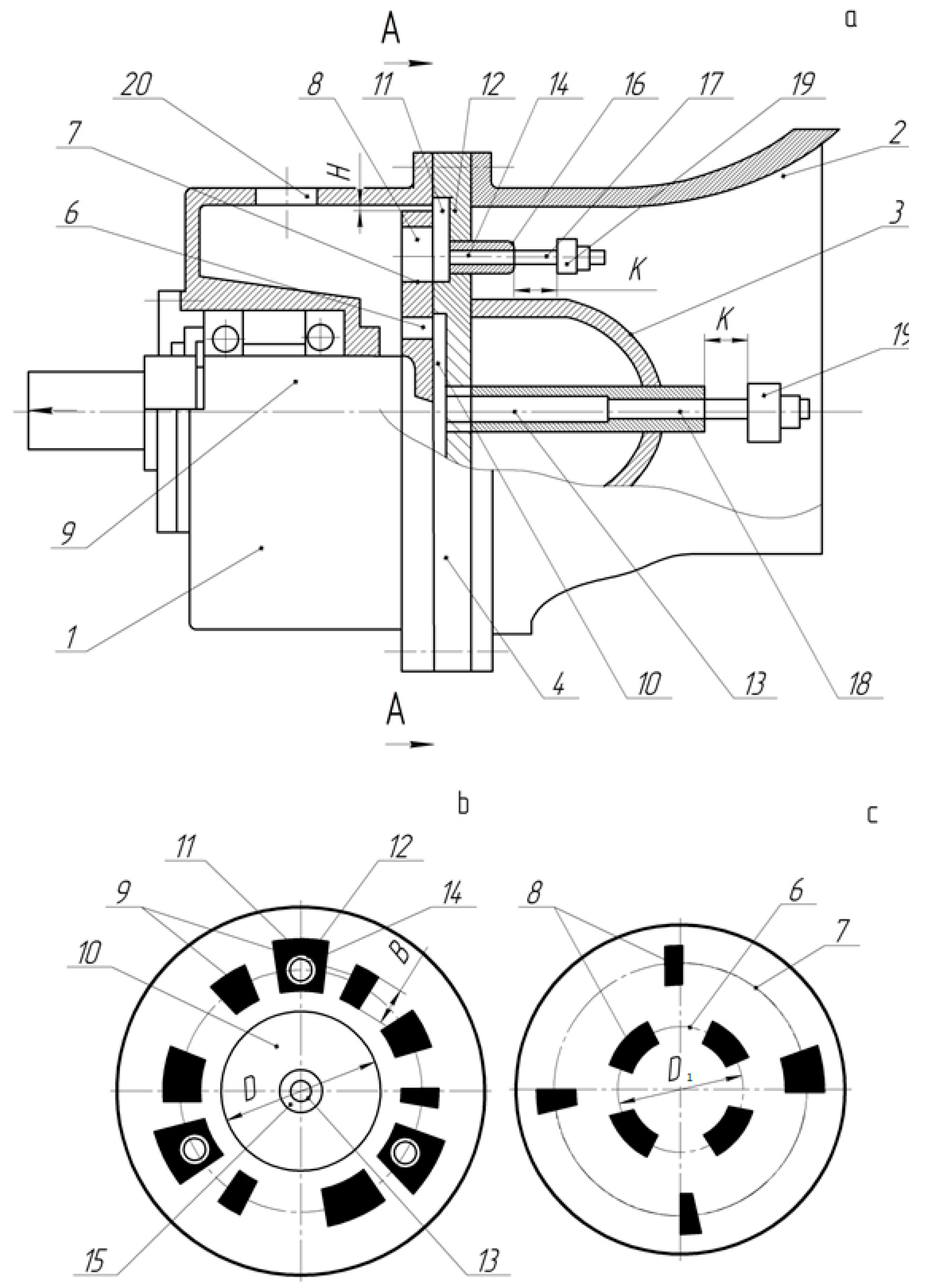
Figure 1). The exhaust gases flow under pressure and enter from the engine through the pipeline in the inner cavity of the baffler. The stator prevents the further movement of the exhaust gases flow from the engine, breaking them into separate components in the form of flat flows, formed by the stator windows. Going further, these flows mount the rotating rotor disk, which, while traversing them, creates the radiation of a certain frequency spectrum width (
Figure 1).
The rotor system consists of the body 1, to which the voice tube 2 with the hollow neck 3 and the stator 4 is fixed. In the body 1, the disk rotor 5 with two rows 6 and 7 of windows
B is installed. The stator 4 has one row of windows 9 and is provided with the groove 10 of the diameter
D (
Figure 1b) made on its inner face, and with the radial slots 11 in the walls of the groove 10 and the slots 11. The gas-jet whistles 14 and 15 are fixed, respectively, with the help of the through-holes 12, 13 made in them. Thus, the diameter
D of the groove 10 is made bigger than the diameter
D1 (
Figure 1c) of the adjacent to its axis set of the windows 6; and the slots 11 are situated in the lintels between the windows 9 of the stator 4, with the length
B and jump the radial gap
H between the body 1 and the rotor disk 5. The sizes and the order of placement of the stator and rotor windows depend on the structure of the expected spectrum of sound fluctuations; they are defined with the help of temporary function of the airflow modulation. The gas-jet whistles 14 and 15 of the sound fluctuations have a known construction; and each of them consists of the blast nozzle 16, in which the stem 17 is fixed with a gap relating to the nozzle edges. The reinforced part of the stem has the slotted holes 18 for the air coming through the nozzle, and on the thinned part, the resonator 19 is fixed with the help of a screw and a check-nut. The resonator 19 can be united with the nozzle and the plug with adjusting nuts (they are not shown/instead the stem 17). The parameters of the initiated sound by the whistles depend on the diameters of the nozzle, the stem and the resonator, as well as on its depth and distance
K from the nozzle to the resonator. These sizes are chosen constant and regulated at the designing of the whistles under the known methodologies, or they are defined experimentally. The rotor system operates in the following way. The pressed air comes to the rotor system body though the hole 20. Having received the directed movement, the air is divided into three flows and comes to the loudspeaker, and then into the environment. One airflow goes through the windows 8 of the rotor from the stator window and, being periodically interrupted by the rotating rotor, coming from the stator windows, generates sound fluctuations of the given power and content. The second airflow goes through the gap
H between the rotor and the rotor system body, comes to the slots 11 of the stator and goes out in the loudspeaker through the whistles 14, which generate the additional sound. The third airflow through the row 6 of the rotor windows enters the circular groove 10 of the stator and through the whistle 15 goes out in the loudspeaker, and the whistle generates the sound. The sound fluctuations, generated by the whistles 14 and 15, are combined with the fluctuations from the pulsation of the air-jets coming out from the stator windows and increase the total sound power of the rotor system. Changing the distance
K between the faces of the nozzles and the resonators of the whistles 14 and 15, you can change the structure of the spectrum of the sound fluctuations emitted by the whistles.
Withthe disks sizes small comparative to the wavelength, we can consider the acoustic process the one that subordinates to the linear equations.
With the taken geometry of the windows the airflow modulation function
f(
t) will practically repeat the rotor windows geometry and, that is why, it may be represented in this case as a periodical quasi-trapezoidal function (
Figure 2) with the period
T = 2
π/
ω. Here
ω is rotor rotational rate in s
−1. The unit impulse time length (
t0 +
t1) is defined by the equation (
t0 +
t1) =
T/
m, where
m is the number of equal sectors (places), on which the rotor circle is divided. Therefore, the unit impulse time length will define the minimal size of the rotor window.
In principle, the modulation function form can take another form and is defined in each certain case experimentally, as here, among other things, also parameters of the engine compressor system of the combat vehicle play an important role [
33]. So, for example, the modulation function can have the form of the commuted sinusoid, of the triangular form, conjugate arcs of parabolas, as well as other, more complicated, configurations.
At the same time, during the rotor system operation, simultaneous air output is unfailingly possible not only through one, but also through several windows. This will influence the pressure of the jet going through the rotor window.
It is natural that for implementation of the force-majeuremovement of the combat vehicle, realization of full and efficient, time-sensitive, burning of the fuel in the working engine chamber is needed. Presence of the “flat noise” will confirm the fulfillment of these requirements. Therefore, in order to ensure the realization of the “flat noise” in the engine baffler, it is necessary to ensure the stochastic nature of the rotor disk distribution. Residual cyclical quadratic chain code may serve as an efficient means of this solution. The definition of the windows location on the rotor can take place in such a way that two windows or more will be able to locate nearby, and the others, on the contrary, may be absent. On those districts where the windows are placed, the meaning of the modulation function is defined by the equation f(t) = λk f0(0 ≤ λk ≤ 1, k is the number of the district), where the windows are absent—the modulation function will be equal to zero.
In order to receive the required form of the modulation function it is enough to ensure the pressure in the coming jet is not less than 2…3 atm.
Let us take for simplicity the modulation function
f(
t) even and periodical, i.e.,
f(
t) =
f(
t +
T). In this case, it can be represented as a trigonometric-series expansion
with coefficients
where
n is the number of the harmonic curve;
f0 is the pulse height; π = 3.14.
Not considering those districts where the modulation function is equal to zero, i.e.,
f(
t) = 0 and, making summing only on the districts with the pulses, where the windows are present, we will receive
where
p is the number of the single pulses during the period
T, that is why 1 <
p ≤
m; the sum
means that the meanings of
k parameter are taken not in succession, but only for the districts with the pulses, i.e.,
f(
t) =
λkf0;
t1 is the time of forming of the pulse front.
Therefore, the modulation function will have the form
The Formula (2) is fair for the case when there is only one single radial window on the stator. Let us mark on the stator
s windows of the same size, equidistant from the stator disk center and removed relating to the basic axis at the angle
φi (
Figure 3). Then, the modulation function of the whole exhaust gases flow going through the rotor system will be equal to the sum of the modulation functions of all the windows (
Figure 4 and
Figure 5). The modulation function can be represented by trapezoidal (
Figure 4) or triangular (
Figure 5).
The marked example above allows for writing the modulation function in the form of [
34]:
where
ti =
φi/
ω.
Therefore, the integrated modulation function, taking into account (3), will be defined by the equation
where
s is the windows number.
In the final form the modulation function may be represented by the equation
Having marked,
we can calculate the amplitudes
of the spectrum harmonic curves, having used the well-known Parseval equality [
35]
Let us define the rotor system spectrum, having supposed to be specific, that on the stator 8 same radial windows are placed equally, in π/4 rad, the sizes of which are equal to the smallest across the width rotor window and to the biggest one across the height (
Figure 6). Let us take the number of places
m on the rotor equal to, for example, 59.
We divide the rotor disk circular curve into 59 equal parts (number of places m = 59). In the open interval of numbers 0…59 we calculate the perfect squares: 0, 1, 4, 9 and so on.
Further, we define the rests from subtraction from each number from this row the summand m = 59.
According to the residual cyclical quadratic chain code, it will ensure the random nature of the distribution of the windows on the rotor disk.
Having carried out the mentioned procedure, we can define that the windows on the rotor disk must be at 0, 1, 3, 4, 5, 7, 9, 12, 16, 17, 19, 20, 21, 22, 25, 26, 27, 28, 29, 35, 36, 41, 45, 46, 48, 49, 51, 53 and 57 intervals (
Figure 7). Therefore, the windows number on the rotor is equal to 15.
Let us introduce a notation
and define the spectrum content of the generated by the rotor system noise for the following numerical values of the parameters: ω = 300 s
−1 (
n = 3·10
3 rpm), φ
1 = 0, (
t0 +
t1) = 1.77·10
−4 s.
Let us first review a simpler case when λ1 = λ2 = … = λp = 1, that means that the height of all the rotor windows is the same.
As the numerical analysis shows, the rotor system spectrum with the places number
m = 59 has irregular frequency characteristics with several “peaks” (
Figure 8). It is evident that the average process performance is distributed here unevenly by frequency. So, two spectral bands—
n = 25…35 and
n = 50…55 have amplitudes two times bigger than the spectral components
n = 35…50 and
n = 55…65 have, and in 3…4 times bigger that the other components of the spectrum. Concerning forms with numbers higher than 95 are practically absent in the rotor system spectrum.
The taken mechanical and mathematical models of the rotor system, as is seen, confirm the possibility of generating of the sound radiation by the chosen technical implementation. The given analytical dependencies allow carrying out of the numerical analysis of the amplitudes of the rotor system spectrum frequency components in the function of the set values of the construction parameters and quantitative researches as to the evaluation of the rotor system abilities for formation of the sound influence of the wished structure.
This approach is used to model rotating dynamic systems that have local damage and additional sources of excitation [
36]. This confirms the assumption about the possibility of using the presented model to analyze the influence of the characteristics of the rotor system on the parameters of the fuel combustion process.
3. Result and Discussion
Let us review the task of forming the wide-band sound waves spectrum in the form of flat noiseon the exit of the baffler. The sound waves come to the baffler through the pipeline from the engine in the jet of the engine combustion product.
For this goal, let us install inside the baffler on its exit two coaxial similar disks—an immovable stator and a movable rotor, coaxial—with it. Both have the given number of radial reach-through “windows” on their surface. To be specific, let us limit the frequency bandwidth by the number of forms equal to 100, i.e., let us suppose that the number of forms n = 100.
The task of optimization in this case resolves itself into the analysis of dependency
Let us define at what values of m, λk and φi the amplitude of the spectral components of the generated noise will be constant by value.
Let us illustrate the solution of the set task at the example of the modulation function in the form of rectangular pulses, represented analytically by the equation:
from where it is easy to define the amplitude of the spectrum components
As the further calculations show, the change of quasi-trapezoid form of the modulation function for a rectangular one does not make principal differences in the evaluation of the spectrum structure, i.e., it is taken as an even function in the form of the cosine . At the same time, a significant simplification of the mathematical apparatus of the solved task is reached.
On the other hand, to define the acoustic radiation performance not only the modulation function form is important, but also the maximum flow value [
37]. Taking into account the Equations (9) and (10), the Formula (8) takes the form:
Here m is the number of equal districts on which the rotor circle is divided; f(t) = λkf0 (0 ≤ λk ≤ 1, k is the district number) is the modulation function on those districts where the windows are marked; f0 is the pulse height; φi is the angle for which the equidistant from the center stator disks of the window are replaced relating to the basic radial line; the sum means that the values of k parameter are taken not evenly, but only for the districts with pulses; p is the number of single pulses during the period T, that is why 1 < p ≤ m.
From the Formula (11), you can see that the equality to zero will be fulfilled at the condition
as the rest factors are positive beforehand. Hereof it follows that the constancy of the amplitude value of the acoustic radiation spectrum generated by the rotor system, does not depend on the height of the “windows”
and the geometry of the placing of the windows on the stator disk
φi, but it depends only on the number of places
m on the rotor. In other words, it is necessary that the following conditions were satisfied
or
Let us first review the Equation (13), having represented the function sin(2π
n/m) in the form of the exponential series:
(15)
Let us suppose
n = 150. Let us take only the first expansion term in the series (15). Then
From here
m = ∞. Having left in the equation only two first expansion terms
we find that
m = 276, and for the three first terms
we will receive
m1 = 275.
The Equation (14), given in the form of the exponential series, has the solution
m = ∞ at the limitation of expansion by only two first terms:
Let us take three first expansion terms of the function
tg (π
n/
m):
This equation has radicals m1 = 0 and m2 = −39.15.
For the four first expansion terms
According to Moivre formula
and the module of this number
Therefore, the found optimal value of the number of places m, like in the above case, will be equal to 276. Considering this, let us define, using the Formula (10), the amplitudes of the rotor system spectrum with the number of places on the rotor m = 276.
The optimization of the content and structure of the rotor system spectrum is presented in the form of a program with use of the programming module of the computer algebra system PTC MathCad Prime 5.
The program listing is given in
Figure 9. The results of the programming are shown in
Figure 10.
The program is a classic version of procedural programming using cycles with a known number of repetitions, which allows you to scale the calculation process by substituting the required number of harmonics (
Figure 9). The result of the program is the derivation of the spectrum of the rotor system, which for given parameters is a distribution with almost linear increase in amplitude (
Figure 10).
The results of the numerical analysis are given in
Figure 11, thusfor simplicity it is supposed that
λ1 =
λ2 =
… =
λp = 1. The diagram shows the centered values of the amplitudes values, i.e.,
As you can see, when the number of places on the rotor disk is equal to
m = 276, the rotor system spectrum practically resembles the “flat noise” (
Figure 12). For comparison, in
Figure 13 a rotor system spectrum with quasi-trapezoidal modulation function is shown. The coincidence of the diagrams is satisfactory.
Therefore, at m = 276, the rotor system generates the sound waves with wide-band frequency band approaching the flat noise. The level of the acoustic pressure is proportional to the value f0 and, naturally, may be increased or decreased on the account of the change of the “window” height.
As noted in [
38], the generation of the spectrum of such a frequency composition has a positive effect on the characteristics. The conducted researches confirm the fact of the possibility of increasingthecharacteristics of the system under conditions of realization in the uniform distribution of amplitudes of fluctuations in the set range.
Having used the residual cyclical quadratic chain code, we can show the system rotor disk at
m = 276 (
Figure 14). The windows on the rotor disk are put in the intervals 1, 3, 4, 9, 12, 13, 16, 24, 25, 36, 48, 49, 52, 64, 69, 72, 73, 81, 85, 93, 96, 100,105, 108, 117, 121, 124, 133, 141, 144, 156, 165. 177, 184, 193, 208, 213, 216, 220, 225, 232, 253, 256, 261, 265. The total number of windows is equal to
46 (some windows are situated nearby, forming wider slots on the disk).
Therefore, the task of optimization of the rotor system spectrum in a comparatively wide range of frequencies has been solved (n = 150). Such harmonic spectral components are proportional to the radial size of the rotor windows, as well as invariant to the number and mutual corner position of the windows on the stator disk. The constancy of the radiation level is defined only by the number m.
The real rotor system spectrum for the optimal number m = 276 will have the content taking the intermediate place between two modulation functions—quasi-trapezoidal and triangular. On the other hand, if putting a shutter with the given geometrical configuration of the windows behind the stator, then you can receive the wished spectrum according to the solved task.
The carried out analysis enablesmaking a conclusion about the possibility of change of the spectrum and the intensity of the rotor system sound field by way of a different combination of the modulation functions—trapezoidal, triangular or other forms. This is confirmed by the results presented in [
39].
Continuing to analyze the abilities of the proposed disk system, taking into account the perspective of its use on the base of the residual cyclical quadratic chain code, we set out the perspectives of a more detailed study of the proposed method for further use. In particular, dealingwiththe use of other forms of the “windows”, of more complicated forms (a star), or of their combination (commuted sinusoids).


