Article

CO2 Recycling in the Iron and Steel Industry via Power-to-Gas and Oxy-Fuel Combustion

1
Escuela de Ingeniería y Arquitectura, Universidad de Zaragoza, María de Luna 3, 50018 Zaragoza, Spain
2
Graduate School of Creative Science and Engineering, Waseda University, Tokyo 169-8555, Japan
3
Department of Mechanical Engineering, Khalifa University, Abu Dhabi P.O. Box 127788, United Arab Emirates
*
Author to whom correspondence should be addressed.
Energies 2021, 14(21), 7090; https://doi.org/10.3390/en14217090
Submission received: 27 September 2021 / Revised: 20 October 2021 / Accepted: 22 October 2021 / Published: 29 October 2021

Abstract

:
The iron and steel industry is the largest energy-consuming sector in the world. It is responsible for emitting 4–5% of the total anthropogenic CO2. As an energy-intensive industry, it is essential that the iron and steel sector accomplishes important carbon emission reduction. Carbon capture is one of the most promising alternatives to achieve this aim. Moreover, if carbon utilization via power-to-gas is integrated with carbon capture, there could be a significant increase in the interest of this alternative in the iron and steel sector. This paper presents several simulations to integrate oxy-fuel processes and power-to-gas in a steel plant, and compares gas productions (coke oven gas, blast furnace gas, and blast oxygen furnace gas), energy requirements, and carbon reduction with a base case in order to obtain the technical feasibility of the proposals. Two different power-to-gas technology implementations were selected, together with the oxy blast furnace and the top gas recycling technologies. These integrations are based on three strategies: (i) converting the blast furnace (BF) process into an oxy-fuel process, (ii) recirculating blast furnace gas (BFG) back to the BF itself, and (iii) using a methanation process to generate CH4 and also introduce it to the BF. Applying these improvements to the steel industry, we achieved reductions in CO2 emissions of up to 8%, and reductions in coal fuel consumption of 12.8%. On the basis of the results, we are able to conclude that the energy required to achieve the above emission savings could be as low as 4.9 MJ/kg CO2 for the second implementation. These values highlight the importance of carrying out future research in the implementation of carbon capture and power-to-gas in the industrial sector.

1. Introduction

The iron and steel sector is one of the most energy- and carbon-intensive in the world. Iron and steel making processes are still mostly coal-based and thus highly dependent on fossil fuels, releasing a substantial amount of CO2 [1]. According to the Intergovernmental Panel on Climate Change (IPCC), the steel industry accounts for 4–5% of the total world CO2 emission. It is the second largest consumer of industrial energy, consuming around 616 Mtoe (25.8 EJ) [2].
The iron and steel industry has a complex structure. However, only a limited number of processes are used worldwide that use similar energy resources and raw materials. Globally, steel is produced using two main routes, the blast furnace–basic oxygen furnace route (BF-BOF) and the direct scrap smelting route (electric arc furnace (EAF)). The BF-BOF route uses mainly iron ore, and depending on the facility, up to 30% scrap. The EAF route mainly uses scrap, and depending on the facility, up to 30% iron and iron ore [2,3,4].
Another fundamental difference between the two routes is the nature of the energy input. In the case of the BF-BOF, mainly coke is used as fuel, while the EAF route produces steel using mainly recycled steel and electricity. The overall process of the two main steel production routes is depicted in Figure 1.
The BF-BOF route consists of several processes: sintering, coke oven, blast furnace, basic oxygen furnace, and the final stage of casting and rolling. The sintering is used to agglomerate iron ore. The coke oven allows for the obtaining of coke from coal by pyrolysis. In the BF, the iron ore is reduced by coke obtaining pig iron, then the BOF lowers the carbon content of the iron thus obtaining steel, and finally the hot metal passes through casting and rolling to obtain the final desired form. Along this processes, different waste exhaust fuel gases are obtained, which can be used in the steel plant (coke oven gas (COG), blast furnace gas (BFG), and basic oxygen furnace gas (BOFG)). All of them contain CO2, which is emitted into the atmosphere unless the waste gas is recycled and/or treated.
A third iron and steel production route, the direct reduced iron (DRI)-EAF route, uses natural gas or coal-based syngas as reducing agent in combustion-free reactors to directly reduce the iron ore into metallic iron, which is processed in EAFs to produce steel. DRI processes differ in terms of the iron source (fine ore or pellets) and reactor type (fluidized bed, fixed bed, or shaft furnace). Among them, the commercially available Energiron and Midrex concepts, which use iron pellets in shaft furnaces with countercurrent moving beds, are the best options from an environmental point of view. Although representing significantly smaller steel production market shares than either the BF-BOF or EAF routes, DRI-EAF has the potential for significant carbon abatement.
Aiming for solutions that substantially reduce CO2 while providing additional benefits, power-to-gas (PtG) stands out as a promising candidate [5]. The PtG concept converts renewable electricity into valuable gases using an electrolysis stage and uses CO2 that may come from industrial processes. Conventionally, the conversion of electricity is carried out by water electrolysis, which produces H2. The consumption of this H2 together with CO2 (or CO), through the Sabatier reaction (Equation (1) or Equation (2)), produces methane, water, and heat [6].
CO 2 + 4 H 2   CH 4 + 2 H 2 O   H 298 K = 164.9   kJ / mol
CO + 3 H 2   CH 4 + H 2 O   H 298 K = 206.4   kJ / mol
When the electrolyser is fed from a renewable energy source, the obtained synthetic natural gas (SNG) can be considered neutral in CO2 emissions. The amount of CO2 that is emitted by this SNG is the same as that is required for its own formation [7]. To make the most of this technology, one can use it with oxy-fuel combustion, since it produces a pure stream of CO2 for the methanation, while electrolysis provides pure O2 for the oxy-fuel combustion [7,8,9,10].
In the case of the iron and steel industry, electrolysis can be performed as usual on water to produce H2 or on the CO2 emissions of the industry to obtain syngas (CO2 electrolysis). Both the syngas and the H2 produced can be used in a methanation process to obtain methane (power-to-methane) [11].
Power-to-H2 can be integrated in ironmaking in two ways. The first method consists in injecting the H2 as auxiliary reducing agent in conventional BFs to reduce the carbon content of the fossil reducing gas, while the second technique uses the H2 as reducing agent in DRI reactors. Studies assessing the injection of H2 in BFs show the potential of reducing CO2 emissions by approximately 20%, barely affecting the overall energy demand of the process. In this case, the injected flow of H2 should be around 30 kg H2/t pig iron, to not significantly modify the operating conditions inside the furnace. Regarding the second method, i.e., DRI, integration of power-to-H2 has the potential to lead to the low energy consumption (3.5–3.7 MWh/t steel) and net-zero CO2 emissions (if carbon-free electricity is used, corresponding to 97–100% emission reduction). Still, to make the power-to-H2-DRI route competitive, carbon allowances should reach approximately EUR 62 per t CO2 and electricity price should be below EUR 40 per MWhe [11]. The subsequent process following the DRI, i.e., the EAF, can also benefit from power-to-methane integrations, as partial substitution of electrical energy by natural gas in EAF may be beneficial for CO2 reduction, thanks to the increment in the efficiency of the process [12].
Since 95% of the world’s iron production is coal-based, it is important to focus on the BF-BOF route, which is the focus of this study. Power-to-syngas and power-to-methane can supply a useful fuel to be injected in a conventional BF, acting as a renewable reducing agent (recycled CO2) [11]. Recent studies have concluded that CO2 emission reduction in power-to-syngas, compared to conventional ironmaking, could be in the range of 11% to 22%, with typical electrolysis capacities of 100–900 MW. In the case of power-to-methane, the CO2 reduction would be between 13% and 19%, requiring water electrolysis power capacities of about 880 MW [11,13].
The objective of this paper was to study a novel concept that integrates power-to-gas technology in the iron and steel industry, together with oxy-fuel combustion and top gas recycling. Two types of integration, which differ in the source of the H2 (water electrolysis or COG), were studied and compared to a reference iron and steel plant in terms of energy requirement and emission reduction. The main novelty of the study relied on the reduction of energy penalties thanks to the combination of power-to-gas and oxy-fuel combustion, which has not been quantified so far in the literature specifically for the iron and steel industry.

2. Description of Case Studies

Three case studies were undertaken to evaluate the energy requirements and carbon emission reductions of power-to-gas (PtG) integrated with blast furnace-basic oxygen furnace (BF-BOF) plants relative to a conventional reference BF-BOF process. The reference plant is described in Section 2.1. The proposed power-to-methane integration in ironmaking with oxy-fuel combustion and top gas recycling (TGR) is described in Section 2.2, and methanation of coke oven gas (COG) integration in ironmaking with oxy-fuel combustion and TGR in Section 2.3.

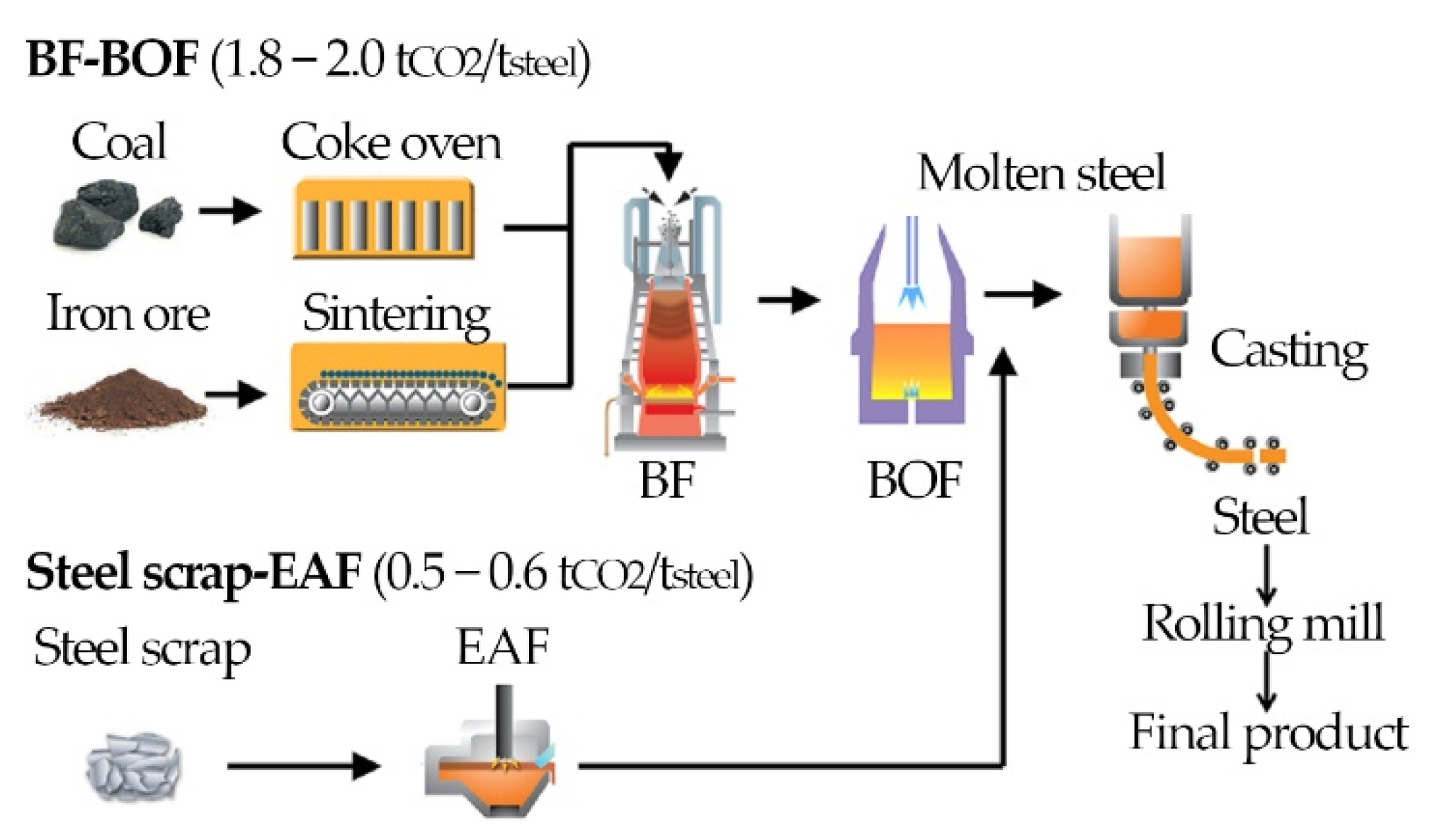
2.1. Case 0: Reference Plant for BF-BOF Ironmaking

The plant consists of a sintering process, coke oven, hot stoves, BF, air separation unit (ASU), BOF, and casting and rolling. The block diagram of the reference ironmaking plant is shown in Figure 2, for which an average production of 2.8 million tsteel/year (7.7 kt/day) was assumed [14]. For the sake of simplicity, secondary processes were neglected (e.g., material recirculation in sintering), such as in similar studies [15,16]. The relevance of these processes to this study is minor since the objective was to conduct a first assessment of the novel integration under overall energy and mass balances.
The main input mass flows were iron ore, coal (converted to pure C in the coke oven), and air (for combustion in BF and for oxygen production in the ASU), as shown in Figure 2. Regarding the inputs to the BOF, we assumed that only pig iron was used (without scrap metal), as in others studies [3,4,15,16]. Those processes requiring heat at high temperature were supplied with thermal energy by consuming part of the fuel gases by-produced in the coke oven, BF and BOF (Table 1) instead of using additional fossil fuels.
In addition, there was a power plant for the utilization of the remaining COG, BFG, and BOFG, as well as for gas streams at high temperature coming from cooling processes (sinter, slag, and coke cooling).

2.2. Case 1: Power-to-Methane Integration in Ironmaking with Oxy-Fuel Combustion and TGR

The modified ironmaking plant integrated with power-to-methane in Case Study 1 is depicted in Figure 3. The BF was here operated under oxy-fuel regime, and coke input to the BF was partially replaced by synthetic methane (stream 140, Figure 3). Part of the blast furnace gas (BFG) (stream 157) was recirculated (top gas recycling (TGR)), and the other was diverted to the power-to-gas plant (stream 157). Here, the emissions of the BF were used to obtain synthetic methane again by combining them with the H2 from a low temperature electrolyser (stream 182). Thus, a continuous recycling of CO2 was established. Moreover, the O2 from the electrolyser (stream 183) was used for the oxy-fuel combustion in the BF, which allowed us to significantly reduce the ASU energy consumption. In addition to the above new equipment necessary for the power-to-gas integration, new preheating blocks (O2 + BFG preheating and CH4 preheating) were also included.
The oxy-blast furnace chosen for this case study ran in a nitrogen-free atmosphere. A pure stream of oxygen was introduced through the tuyeres instead of hot air, in order to obtain exhaust gases that were also nitrogen-free (composed only of CO2 and CO). This concept is closely related to the top gas recycling. The TGR technology consists of recirculating the exhaust gases (mainly CO2, CO, and H2) back to the BF to reduce the coke (and consequently the air) consumption, which made the final BFG contain less N2. In the present case, both oxyfuel and TGR technologies were simultaneously applied. The reason for applying TGR was that introducing a reducing gas (CO) diminished the coke consumption, while separating CO and CO2 would have an energy penalization. The selected proportion between O2 and CO2 in the oxy-blast furnace was 40% O2–60% CO2.
The gas introduced in the methanation reactor was BFG, since it contains no nitrogen and large proportions of CO, which reduced the methanator H2 requirement.

2.3. Case 2: Methanation of COG Integration in Ironmaking with Oxy-Fuel Combustion and TGR

The modified ironmaking plant for power-to-methane integration for Case Study 2 is depicted in Figure 4. In this case, the ironmaking worked in the same oxy-fuel regime with TFG as in Case 1, but here the COG (stream 114/382) was used as H2 source in the methanation process instead of pure H2. Since COG does not contain nitrogen, and has large contents of CH4, H2, and CO, it completely avoided the need for an electrolyser and its associated investment cost, unlike in Case 1. The rest of the operating conditions and assumptions remained the same as in the Case Study 1.
In summary, in terms of produced gas utilization, Case 1 recycled BFG to the methanator and SNG to the BF, while Case 2 recycled both BFG and COG to the methanator and SNG to the BF.

3. Methodology

The modelling assumptions common to the analyses of Cases 0–2 plant concepts included steady-state conditions, ideal gases, and adiabatic reactions. Further case-specific assumptions are documented in Section 3.1.
The modelling methodology is based on overall mass balance (Equation (3)) and energy balance (Equation (4)) in steady state, applied to each equipment in Case 0, Case 1, and Case 2 plant layouts (Figure 2, Figure 3 and Figure 4).
0 = m i m o
0 = Q W + m i h i m o h o
where m is the mass flow, h the specific enthalpy, W the network, and Q the net heat transfer. Enthalpy can be written as Equation (5), where f h T r e f is the enthalpy of formation at the reference temperature and c p is the temperature-dependent specific heat.
h i = f h i T r e f + T r e f T c p , i d T
When necessary, data from the literature were used. The specific assumptions for the subsystems (ironmaking, power plant, and power-to-gas) are described in the following subsections.

3.1. Iron and Steel Plant

For Case 0, in the ironmaking process (BF), instead of fixing the input mass flows of iron ore (Stream 1, Figure 2), coal (Stream 11, Figure 2), and hot blast (Stream 20, Figure 2), we calculated them from the mass balance by assuming a final composition of the steel and the BFG, taken from [17] and [3], respectively. The mass fraction of iron was set at 96% in pig iron and 99.7% in steel, with carbon as the remaining component (other elements such as Si or Mn were neglected) [17]. The mole fraction of the BFG was fixed according to data from [3] in Table 1. The mass flows of the pig iron (Stream 31, Figure 2), BFG (Stream 26, Figure 2), and slag (Stream 27, Figure 2) were also calculated in the BF’s mass and energy balances. The air for the hot blast was heated to 1200 °C by means of COG (Stream 22, Figure 2) [18].
The coal added to the sintering process was set at 5 wt % of the amount of iron treated [19]. The temperature of the sintered iron at the exit of this sintering process was assumed at 800 °C (Stream 3, Figure 2), which was later reduced to 150 °C (Stream 4, Figure 2) [16]. The amount of BOFG (Stream 9, Figure 2) and the cooling air (Stream 5, Figure 2) were calculated with the mass and energy balances for each block.
The coke produced in the coke oven was assumed as pure carbon, and the mole fraction of the COG was fixed as shown in Table 1. The coke temperatures before and after the coke dry quenching (CDQ) were 1100 °C (Stream 13, Figure 2) and 150 °C (Stream 13, Figure 2), respectively [2]. The mass flow of COG was calculated in a mass balance between the input coal and the output coke. The self-consumed COG and the inert gas needed for the CDQ were calculated in mass and energy balances for each block.
Regarding the air separation unit required for the BOF, we assumed that it produced pure streams of O2 (Stream 33, Figure 2) and N2 (Stream 34, Figure 2). The electricity consumption of the ASU was set at 1440 kJ per kilogram of oxygen produced [20]. The pure stream of oxygen was heated up to 1650 °C [3] by burning COG (Stream 37, Figure 2).
In the BOF, the amount of hot steel produced was assumed as a unit reference (1 kg of steel). The composition of the BOFG was again fixed according to Table 1, and the mass flows of slags (Stream 40, Figure 2), BOFG (Stream 39, Figure 2), and O2 (Stream 35, Figure 2) were calculated by a mass and energy balance in the BOF.
For Cases 1 and 2, the assumptions and methodology explained for Case 0 were the same, with some minor changes. In the BF’s mass balance, not only the iron ore, coal, BFG, and pig iron mass flows were calculated, but also the O2 (Stream 130, Figure 3), CH4 (Stream 140, Figure 3), and BFG (recirculated) (Stream 175, Figure 3). The O2 demand for the BOF remained the same (Stream 195, Figure 2), but the amount of O2 produced by the ASU was lower (Stream 192, Figure 2), since a by-product stream of O2 from the electrolyser was used (Stream 183, Figure 3) (only for Case 1).

3.2. Power Plant

This plant produces electricity for self-consumption from the energetic gases of the steel plant (i.e., COG, BFG, BOFG) and from heat streams from other heat recovery processes (i.e., coke dry quenching and slag cooling). An overall efficiency of 17.9% was assumed for the power plant [16], because of the low temperatures of the heat recovery flows, the gas treatment before entering the boiler, and the limited calorific value of the gases (due to the high CO2 content and the dilution in the N2 present in the air).

3.3. Power-to-Gas Plant

In Case Study 1, the H2 was produced from water electrolysis, while in Case Study 2, the H2 came from the COG, which was directly diverted to methanation. The COG contained enough H2 to produce all the necessary methane, but lacked CO2. Therefore, some BFG was also diverted to methanation to fulfil the stoichiometric requirements of reactions (1) and (2). It is important to note that in Case 2, no electrolyser was needed. The methanation plant worked at 300 °C and 30 bar [7].
For the sake of simplicity, the electrolyser was assumed to produce pure streams of O2 and H2, while the methanation was set to produce a pure stream of methane. By these assumptions, as well as reactions Equations (1) and (2), we can easily solve the mass balance. Regarding electricity, the energy consumption of the low-temperature electrolyser was fixed at 4.5 kWh/Nm3 [7,8,21].

4. Results and Discussion

The modelling results obtained for Cases 0, 1, and 2 are presented and discussed in Section 4.1, Section 4.2 and Section 4.3, respectively. In addition, the corresponding stream data for each Case are presented in the Appendix A.

4.1. Case 0: Reference Plant for BF-BOF Ironmaking

The mass flows of Case 0 are summarized in Table 2, where the main calculated variables are compared to data from the literature [3,11,15,16,17]. All results lay within reasonable limits, thus validating the results of the reference case, which was the basis for the rest of the analyses. As already stated in the methodology section, the input streams were calculated as a function of a desired steel output composition.
The total electricity consumption of the ironmaking process was 874 MJ/t steel, and the electricity produced by the power plant was 1260 MJ/t steel (Table 3); therefore, the overall process was self-sufficient (typical power productions were about 1300 MJ/t steel in on-site power plants [15]). Regarding the thermal energy consumption, the BF was the largest consumer, representing 55% of the overall process when the air heating was accounted for (in the literature, the energy consumption of the blast furnace (BF) process can reach 70% of the total plant [3]). The heat removed by cooling the stoves of the BF was fixed at 1260 MJ/t pig iron, according to [22].
The percentage of utilization of COG, BFG, and BOFG by type of process is presented in Table 4, together with their energy density and mass flow production. In overall terms, the 46.5% energy content of these gases was used in internal processes of the plant, while the rest was used in the power plant (Figure 5). The total CO2 emissions of the plant were 1718 kg/t steel (Figure 6), with BFG as the major emitting source (1368 kg/t steel). According to the literature, BF CO2 emissions may range between 1270 and 1550 kg/t steel, and total emissions up to 2200 kg/t steel [16,23].

4.2. Case 1: Power-to-Methane Integration in Ironmaking with Oxy-Fuel Combustion and TGR

In Case 1, the installation included an oxygen blast furnace with top gas recycling and a power-to-gas (PtG) plant. The latter converted the CO2 emissions into synthetic methane to be reinjected in the blast furnace, thus replacing some fossil fuel. The power capacity of the power-to-gas plant was sized to produce a SNG amount enough to replace 50 kg coke/t steel. According to the simulation, the replacement ratio was 1.3 kg SNG/kg coke, and therefore the necessary H2 was 27 kg H2/t steel. Assuming a steel production of 7.7 kt/day, we found the electrolysis power capacity to be installed was 431.9 MWe if working continuously (4.5 kWh/Nm3 H2 electricity consumption). Currently, the world’s largest planned electrolyser farm has a power capacity of 100 MW [24], which is within the same order of magnitude as the PtG capacity required for the proposed case study.
The total electricity consumption of the overall plant was 6.1 MJ/t steel, which means an increment of 702% with respect to the base case scenario (Table 3). The electricity demand of those processes already existing in the base simulation was kept constant [15], and the new electricity consumptions corresponding to the PtG plant were added (the production of H2 represents 81% of the total electricity consumption). Despite the power plant now producing 14.5% more power (1.4 MJ/t steel), the overall process is no longer self-sufficient. The remaining electricity (4.7 MJ/t steel) should come from renewable sources to avoid further emissions. Within this framework, a renewable facility working continuously of 417 MWe is required to satisfy this electricity demand.
Regarding thermal energy consumption (Table 3), the largest consumer is still the blast furnace (60.3% of the total needs). Its energy consumption increased by 9.4% due to oxy-fuel combustion. However, the coke oven consumption decreased by 11.6% due to the reduction of fossil fuel input. In the air heating furnace, we had to heat CO2 for the oxy-combustion instead of air, resulting in a slight reduction of the thermal energy consumption.
In this integration, BFG was used in top gas recycling and methanation, and therefore the percentage of utilization of fuel gases by type of process remarkably changed (Table 4). Here, only 35.7% of the energy content of these gases was used in the internal processes of ironmaking and 21.4% in the power plant (Figure 5). The remaining was mostly recirculated to the blast furnace (36.1%), and a small fraction was diverted to methanation (4.7%).
Regarding CO2, the BF was still the larger emitting source, producing 1255 kg/t steel. In total, the CO2 emissions were 1582 kg/t steel, which was 8% less than in the reference case (Case 0, Figure 6). Thus, 136 kg CO2/t steel were avoided by consuming 5079 MJ/t steel additional electrical energy, and a saving of 3.34 MJ/kg CO2 by means of coke reduction was achieved, which means a CO2 avoidance penalization of 34 MJ/kg CO2. Comparing this penalization with those in other processes, such as power-to-syngas (4.8–10.8 MJ/kg CO2 [11]) and amine scrubbing (3–4 MJ/kg CO2 [25,26]), indicates that Case 1 configuration does not present any energy advantage.

4.3. Case 2: Methanation of COG Integration in Ironmaking with Oxy-Fuel Combustion and TGR

In this case, the ironmaking process worked under oxy-fuel regime with top gas recycling as in Case 1. However, here, the H2 source for the methanation process was the coke oven gas instead of pure H2.
The total electrical consumption of this plant was 1382 MJ/t steel. This was well below Case 1 (77% lower) since electrolysis was no longer used, but still above Case 0 (58% higher) because of the gas compression in the methanation process and the production of O2 for the oxy-fuel blast furnace. Moreover, since COG was here used in methanation, the power plant only produced 652 MJ/t steel (47% of the total electricity consumption, i.e., not self-sufficient). To supply the missing electricity, we required a renewable facility of 65 MWe working continuously, assuming a steel production of 7.7 kt/day. Regarding thermal energy consumption, the requirements are the same than those of Case 1 (Table 3).
In terms of gas utilization (Table 4), the COG was used entirely in methanation instead of in internal plant processes. For this reason, 43.6% of the BFG had to be allocated to this end. The BOFG was also used in the internal processes of the plant (as in the two previous cases). With this implementation, 36.8% of the energy from these gases was used in the internal processes, 4.5% in the power plant, 22.6% in methanation, and 36.1% in top gas recycling (Figure 5).
Regarding emissions, the CO2 that was avoided remained the same as for Case 1 (136 kg CO2/t steel) because the same amount of methane was produced, and therefore the amount of CO2 that was recycled in closed loop did not change. Then, total emissions were 1582 kg/t steel (the BF accounted for 1405 kg CO2/t steel, while the coke oven barely emitted CO2 because COG was used in methanation). Since the electricity consumption increased by 1116 MJ/t steel, the CO2 avoidance penalization was 4.9 MJ/kg CO2. This penalization is in the range of other processes such as power-to-syngas or amine scrubbing, and therefore is energetically competitive.

4.4. Discussion

Figure 7 depicts a Sankey diagram of the energetic gases of the steel industry for the three scenarios: Case 0, Case 1, and Case 2. It can be seen that the energy flow to the power plant was increasingly reduced for each case, thus explaining why a renewable facility is needed. The internal energy use increased in Cases 1 and 2 due to the blocks that were added to the diagram (e.g., CH4 heating). In the methanation section, the same energy was consumed in both Cases 1 and 2, and therefore the main difference was the H2 source, either an electrolyser or the COG. The TGR was not changed in the two integrations, obtaining the energy from the BFG.
Although integrating oxy-fuel combustion in the BF is an interesting option in terms of CO2 mitigation, the technology is not commercial yet (current TRL is 6–7) [27]. Thus far, Zuo and Hirsch [28] reported experimental results from a 9 m3 TGR-BF, combined with a vacuum pressure swing adsorption carbon capture method for removing CO2 of the top gas. They found 24% savings in carbon consumption and 76% reduction in CO2 emissions when assuming underground storage of the corresponding captured CO2 [29]. On average, the carbon input decreased from 470 kg/t pig iron to 350 kg/t pig iron [27]. It is worth mentioning that oxy-fuel combustion is already applied commercially in secondary processes in ironmaking plants, such as during the preheating of ladles and converter, or during the steel reheating and heat treatment. Since the oxy-fuel technology is familiar to the industry, its adoption in BFs is a reasonable option [11]. In fact, the topic is being studied widely in the literature to solve remaining technical issues related to the smoothness of operation (non-linear behavior of the feedback induced by the top gas recycle) [30].

5. Conclusions

A novel concept integrating power-to-gas technology in the ironmaking process, together with oxy-fuel combustion and top gas recycling, was presented. Two integration options were analyzed, differing in the source of H2 for the methanation process (H2 from water electrolysis, Case 1, or syngas from the coke oven, Case 2). In both cases, synthetic natural gas from methanation was injected into the blast furnace to reduce the coke consumption, thus recycling CO2 in a closed loop. The power-to-gas plant was sized to reduce the coke content by 50 kg/t steel. Both Cases 1 and 2 were compared with a conventional ironmaking process (Case 0).
The base case simulation included the sintering process, coke oven, hot stoves, blast furnace, air separation unit, basic oxygen furnace, casting, and power plant. For the power-to-gas (PtG) integrations, an electrolyser (only in Case 1) and methanation plant were added to the simulation, and the blast furnace was run under oxy-fuel conditions with top gas recycling. Mass flows, compositions, and thermal and electricity consumptions were calculated through mass and energy balances.
Savings in CO2 emissions with either of the two PtG implementations were 8%, with a reduction in coal fuel of 12.8%. The energy required to avoid these emissions was 34 MJ/kg CO2 for Case 1 and 4.9 MJ/kg CO2 for Case 2. This remarkable difference was because the first PtG integration required a 431.9 MW electrolyser to produce the H2, while the second used the H2 content of coke oven gas (COG) and therefore an electrolyser was not needed. Under this framework, the only competitive option is Case 2, whose energy penalization is in the range of conventional amine carbon capture [31]. Moreover, it has the advantage of reducing the fuel consumption and reducing geological storage, which are additional benefits regarding economic costs compared to conventional carbon capture and storage.
The energy content of the gases generated in the industry (COG, BFG, and BOFG) are normally used in internal processes, but mainly in the production of electricity. The implementation of the PtG implies a greater consumption of these gases in the internal processes of the plant, as well as in the methanation and recirculation processes. This means that only a small percentage of the gases are diverted to the thermal power plant, making necessary a renewable facility to fulfil the electricity demand (in Case 1 and Case 2, the plant is no longer self-sufficient). Case 1 requires a renewable-based power production 5.2 times larger than Case 2 (417 MW vs 65 MW), due to electrolysis.
This study shows good technical prospects for the future in terms of reducing steelmaking industry emissions. An economic analysis of the proposed alternative processes will be performed in future work.

Author Contributions

Conceptualization, J.P., M.B., L.M.R. and B.P.; methodology, J.P. and M.B.; model, J.P. and M.B.; validation, J.P. and M.B.; formal analysis, J.P.; writing—original draft preparation, J.P. and M.B.; writing—review and editing, V.E.; visualization, J.P. and M.B.; supervision, M.B., L.M.R., B.P. and V.E.; project administration, M.B., L.M.R., B.P. and V.E.; funding acquisition, M.B., L.M.R. and V.E. All authors have read and agreed to the published version of the manuscript.

Funding

The work described in this paper has been supported by both the University of Zaragoza under the project UZ2020-TEC-06 and Khalifa University project CIRA-2020-080. This work has also received funding from the European Union’s Horizon 2020 research and innovation program under the Marie Sklodowska-Curie grant agreement no. 887077.

Institutional Review Board Statement

Not applicable.

Informed Consent Statement

Not applicable.

Data Availability Statement

Not applicable.

Conflicts of Interest

The authors declare no conflict of interest.

Abbreviations

ASUair separation unit
BATbest available technology
BFblast furnace
BFGblast furnace gas
BOFbasic oxygen furnace
BOFGbasic oxygen furnace gas
CDQcoke dry quenching
COcoke oven
COGcoke oven gas
PtGpower-to-gas
SNGsynthetic natural gas
TGRtop gas recycling

Appendix A. Stream Data

Table A1. Specific heat, mass flows, and temperatures for Cases 0, 1 and 2.
StreamcpmTStreamcpmTStreamcpmT
(kJ/kg.K)(kg/kgsteel)(°C) (kJ/kg.K)(kg/kgsteel)(°C) (kJ/kg.K)(kg/kgsteel)(°C)
10.4731.42625490.9070.085251804.180.0895525
20.8350.0713251010.4731.426251814.180.241425
30.4731.4268001020.8350.07132518214.340.0270125
40.4731.4261501030.4731.4268001830.9140.214425
51.0050.6232251040.4731.4261501842.2390.0650625
61.1260.62326501051.0050.6232251854.180.101625
71.1260.47626501061.1260.62326501864.182.66525
81.1260.1476501071.1260.47626501874.182.66580
91.4260.08527251081.1260.1476501901.0050.777225
101.0120.23745001091.4260.08527251911.0380.593825
110.8350.5238251101.0120.23745001920.9140.180325
120.8360.419111001110.8350.4568251930.9140.394725
130.8360.41911501120.8360.365411001940.9140.0887325
149.0350.104813501130.8360.36541501951.1790.088731650
151.0050.668251149.0350.0913613501961.1170.0402625
169.0350.04969251151.0050.4562251971.0050.0591425
171.0120.74085001161.1170.3105251981.0120.104600
181.0380.3646251171.0120.80215002000.9070.08525
191.1780.36468001181.0380.318252010.7490.0851650
201.0051.278251191.1780.3188002021.0050.0618325
211.2081.27812001300.9140.3059252031.1540.06183800
229.0350.05062251311.1420.305912002040.7490.085460
231.0050.6805251320.8420.5324252051.4260.13461650
241.0120.75473001331.3230.532412002060.511650
250.9070.283251341.1170.4782252071.4120.0479525
261.4122.0842001351.0050.7025252081.0050.0826925
270.7490.28312001361.0121.2356002091.0120.1335850
280.7490.2834601371.0370.53252100.5125
291.0050.1754251381.2540.5312003341.4120.478225
301.1540.17548001402.2390.06506253351.0050.702525
310.481.03912001415.6320.0650612003361.0121.235600
321.0050.3825251421.1170.1019253421.4120.101925
330.9140.08873251431.0050.1498253431.0050.149825
341.0380.2922251441.0120.26336003441.0120.2633600
351.1790.0887316501500.9070.283253741.4120.0138425
361.0050.07301251510.7490.28312003761.0981.05925
379.0350.00543251520.7490.2834603829.0350.0910625
381.0120.080966001531.0050.1754253854.180.0088325
391.4260.134616501541.1540.17548003864.180.871425
400.7490.08516501550.481.03912003874.180.871480
410.7490.0854601561.1172.1862003901.0051.70125
421.0050.0847251571.0982.136253911.0381.325
431.1540.08478001584.180.05031253920.9140.394725
440.5116501594.182.352253961.4120.0402625
450.51251604.182.352803971.0050.0591425
461.4260.04795251741.0980.1389253981.0120.104600
471.0050.08269251751.0981.06225
481.0120.13358501761.0980.934325

References

  1. Huitu, K.; Helle, H.; Helle, M.; Kekkonen, M.; Saxén, H. Optimization of steelmaking using fastmet direct reduced iron in the blast furnace. ISIJ Int. 2013, 53, 2038–2046. [Google Scholar] [CrossRef] [Green Version]
  2. Quader, M.A.; Ahmed, S.; Ghazilla, R.A.R.; Ahmed, S.; Dahari, M. A comprehensive review on energy efficient CO2 breakthrough technologies for sustainable green iron and steel manufacturing. Renew. Sustain. Energy Rev. 2015, 50, 594–614. [Google Scholar] [CrossRef]
  3. He, K.; Wang, L. A review of energy use and energy-efficient technologies for the iron and steel industry. Renew. Sustain. Energy Rev. 2017, 70, 1022–1039. [Google Scholar] [CrossRef]
  4. Ariyama, T.; Takahashi, K.; Kawashiri, Y.; Nouchi, T. Diversification of the Ironmaking Process Toward the Long-Term Global Goal for Carbon Dioxide Mitigation. J. Sustain. Metall. 2019, 5, 276–294. [Google Scholar] [CrossRef]
  5. Lisbona, P.; Bailera, M.; Peña, B.; Romeo, L.M. Integration of CO2 capture and conversion. In Advances in Carbon Capture; Rahimpour, M.R., Farsi, M., Makarem, M.A., Eds.; Woodhead Publishing: Cambridge, UK, 2020; pp. 503–522. ISBN 9780128196571. [Google Scholar]
  6. Gao, J.; Wang, Y.; Ping, Y.; Hu, D.; Xu, G.; Gu, F.; Su, F. A thermodynamic analysis of methanation reactions of carbon oxides for the production of synthetic natural gas. RSC Adv. 2012, 2, 2358–2368. [Google Scholar] [CrossRef]
  7. Bailera, M.; Lisbona, P.; Romeo, L.M. Power to gas-oxyfuel boiler hybrid systems. Int. J. Hydrog. Energy 2015, 40, 10168–10175. [Google Scholar] [CrossRef] [Green Version]
  8. Romeo, L.M.; Bailera, M. Design configurations to achieve an effective CO2 use and mitigation through power to gas. J. CO2 Util. 2020, 39, 1–10. [Google Scholar] [CrossRef]
  9. Bailera, M.; Hanak, D.P.; Lisbona, P.; Romeo, L.M. Techno-economic feasibility of power to gas–oxy-fuel boiler hybrid system under uncertainty. Int. J. Hydrog. Energy 2019, 4, 9505–9516. [Google Scholar] [CrossRef] [Green Version]
  10. Eveloy, V. Hybridization of solid oxide electrolysis-based power-to-methane with oxyfuel combustion and carbon dioxide utilization for energy storage. Renew. Sustain. Energy Rev. 2019, 108, 550–571. [Google Scholar] [CrossRef]
  11. Bailera, M.; Lisbona, P.; Peña, B.; Romeo, L.M. A review on CO2 mitigation in the Iron and Steel industry through Power to X processes. J. CO2 Util. 2021, 46, 101456. [Google Scholar] [CrossRef]
  12. Kirschen, M.; Risonarta, V.; Pfeifer, H. Energy efficiency and the influence of gas burners to the energy related carbon dioxide emissions of electric arc furnaces in steel industry. Energy 2009, 34, 1065–1072. [Google Scholar] [CrossRef]
  13. Rosenfeld, D.C.; Böhm, H.; Lindorfer, J.; Lehner, M. Scenario analysis of implementing a power-to-gas and biomass gasification system in an integrated steel plant: A techno-economic and environmental study. Renew. Energy 2020, 147, 1511–1524. [Google Scholar] [CrossRef]
  14. Steelmaking Technologies. CISDI Ingeniering CO. LTD. Available online: http://www.cisdigroup.com/4-steelmaking.html (accessed on 15 September 2021).
  15. He, H.; Guan, H.; Zhu, X.; Lee, H. Assessment on the energy flow and carbon emissions of integrated steelmaking plants. Energy Rep. 2017, 3, 29–36. [Google Scholar] [CrossRef]
  16. Wu, J.; Wang, R.; Pu, G.; Qi, H. Integrated assessment of exergy, energy and carbon dioxide emissions in an iron and steel industrial network. Appl. Energy 2016, 183, 430–444. [Google Scholar] [CrossRef]
  17. Geerdes, M.; Chaigneau, R.; Lingiardi, O.; Molenaar, R.; van Opbergen, R.; Sha, Y.; Warren, P. Modern Blast Furnace Ironmaking an Introduction; IOS Press: Amsterdam, The Netherlands, 2020; ISBN 978-1-64368-123-8. [Google Scholar]
  18. Ariyama, T.; Sato, M.; Nouchi, T.; Takahashi, K. Evolution of blast furnace process toward reductant flexibility and carbon dioxide mitigation in steel works. ISIJ Int. 2016, 56, 1681–1696. [Google Scholar] [CrossRef] [Green Version]
  19. Fisher, L.V.; Barron, A.R. The recycling and reuse of steelmaking slags—A review. Resour. Conserv. Recycl. 2019, 146, 244–255. [Google Scholar] [CrossRef] [Green Version]
  20. Darde, A.; Prabhakar, R.; Tranier, J.P.; Perrin, N. Air separation and flue gas compression and purification units for oxy-coal combustion systems. Energy Procedia 2009, 1, 527–534. [Google Scholar] [CrossRef] [Green Version]
  21. Rönsch, S.; Schneider, J.; Matthischke, S.; Schlüter, M.; Götz, M.; Lefebvre, J.; Prabhakaran, P.; Bajohr, S. Review on methanation—From fundamentals to current projects. Fuel 2016, 166, 276–296. [Google Scholar] [CrossRef]
  22. Biswas, A.K. Principles of Blast Furnace Ironmaking. Theory and Practice; Cootha Publishing House: Brisbane, Australia, 1981. [Google Scholar]
  23. IAE—Iron & Steel Roadmap. 2020. Available online: https://www.iea.org/reports/iron-and-steel-technology-roadmap (accessed on 24 October 2021).
  24. ITM Power to study feasibility of 100 MW P2G energy storage. Fuel Cells Bull. 2018, 2018, 11. [CrossRef]
  25. Arasto, A.; Tsupari, E.; Kärki, J.; Pisilä, E.; Sorsamäki, L. Post-combustion capture of CO2 at an integrated steel mill—Part I: Technical concept analysis. Int. J. Greenh. Gas Control 2013, 16, 271–277. [Google Scholar] [CrossRef]
  26. Tobiesen, F.A.; Svendsen, H.F.; Mejdell, T. Modeling of blast furnace CO2 capture using amine absorbents. Ind. Eng. Chem. Res. 2007, 46, 7811–7819. [Google Scholar] [CrossRef]
  27. Keys, A.; van Hout, M.; Daniels, B. Decarbonisation Options for the Dutch Steel Industry; PBL Netherlands Environmental Assessment Agency: The Hague, The Netherlands, 2019.
  28. Zuo, G.; Hirsch, A. The trial of the Top Gas Recycling Blast Furnace at LKAB’s EBF and Scale-Up. Rev. Métallurgie 2009, 2, 255. [Google Scholar] [CrossRef]
  29. Danloy, G.; Berthelemot, A.; Grant, M.; Borlée, J.; Sert, D.; van der Stel, J.; Jak, H.; Dimastromatteo, V.; Hallin, M.; Eklund, N.; et al. ULCOS—Pilot testing of the low-CO2 Blast Furnace process at the experimental BF in Lulea. Rev. Metall. Cah. D’Inform. Technol. 2009, 106, 1–8. [Google Scholar] [CrossRef] [Green Version]
  30. Zhang, W.; Dai, J.; Li, C.; Yu, X.; Xue, Z.; Saxén, H. A Review on Explorations of the Oxygen Blast Furnace Process. Steel Res. Int. 2021, 92, 202000326. [Google Scholar] [CrossRef]
  31. Bailera, M.; Lisbona, P.; Peña, B.; Romeo, L.M. Energy Storage; Springer International Publishing: Cham, Switzerland, 2020; ISBN 978-3-030-46526-1. [Google Scholar]
Figure 1. Main routes of steel production [4].
Energies 14 07090 g001
Figure 2. Block diagram of the reference ironmaking plant (Case 0).
Energies 14 07090 g002
Figure 3. Block diagram of the integration of power-to-methane in ironmaking with oxy-fuel combustion and TGR (Case 1).
Energies 14 07090 g003
Figure 4. Block diagram of the integration of COG methanation in ironmaking with oxy-fuel combustion and TGR (Case 2).
Energies 14 07090 g004
Figure 5. Use of the energy content of the total gases (COG, BFG, and BOFG) by type of process for each plant layout (i.e., Case 0–2).
Energies 14 07090 g005
Figure 6. CO2 emissions by process for each plant layout (i.e., Case 0–2).
Energies 14 07090 g006
Figure 7. Sankey diagram of the change in the energy utilization inside the ironmaking plant of the energetic gases COG, BOFG, and BFG: (a) Case 0, (b) Case 1, and (c) Case 2.
Energies 14 07090 g007
Table 1. Elemental composition considered for the fuel gases produced as by-products in the ironmaking plant (vol %), according to the ranges reported in [3].
Natural GasCOGBFGBOFG
H205641.5
CH41003000
CO0102566.5
CO2052020
O20102
N2055110
Table 2. Mass flows (kg/t steel) of the main streams calculated for Case 0, Case 1, and Case 2. Bibliographic data were taken from [3,11,15,16,17]. * Input data for solving mass and energy balances.
StreamBibl.Case 0Case 1Case 2
Raw materialsIron ore1550143014301430
Coal560520460460
Coke ovenCOG901109090
Blast furnace (BF)Sinter1550143014301430
Coke400420370370
Air (hot blast)12101280--
O2 (hot blast)--310310
BFG (hot blast)--10601060
CH4 (hot blast)--6565
BFG2420208021902190
Slag280 *280280280
Pig iron1040 *104010401040
Basic oxygen furnace (BOF)O270909090
Steel1000100010001000
Slag80 *808080
BOFG130 *130130130
Power-to-gas (PtG)O2--210-
H2--27-
BFG--13914
COG---91
CH4--6565
Table 3. Main energy streams (MJ/t steel) calculated for Case 0, Case 1, and Case 2. * From: [15].
ProcessCase 0Case 1Case 2
Thermal energy consumptionSintering523523523
Coke oven163114421442
Air (hot blast)1814--
O2 + BFG (hot blast)-12391239
CH4 (hot blast)-431431
Blast furnace291539003900
O2 heating170170170
BOF122812281228
Casting, rolling300300300
Total858192339233
Electricity consumptionSintering *180180180
Coke oven *424242
Blast furnace *376376376
ASU128252568
BOF *128128128
Electrolyser-4991-
H2 compressor-9632
CO2 compressor-5136
Other *202020
Total87461361382
Electricity productionPower plant12601443652
Table 4. Mass flow, energy content, and use of the fuel gases produced in the ironmaking process.
Case 0Case 1Case 2
COGBFGBOFGCOGBFGBOFGCOGBFGBOFG
Mass flow (kg/t steel)1102080130902140130902140130
Energy content (MJ/kg)40.02.76.340.05.76.340.05.76.3
Utilization of the
energy content of the gases by type of
process (%)
Internal use99.1099.0042.299.0043.699.0
Power plant0.91001.01001.61.00.36.01.0
Methanation---06.5099.70.60
TGR---049.70049.70
Publisher’s Note: MDPI stays neutral with regard to jurisdictional claims in published maps and institutional affiliations.

