Abstract
This paper presents a method for reducing the cogging torque for a sloping notch with two notches applied on the stator teeth. The accuracy of FEA was confirmed by a comparison with a previous model using an asymmetric notch for the experiment data and 3D FEA results, followed by a comparison of the cogging torque of a two notches model and a sloping notch model. The sloping notch model was modified to a step-sloping notch model in consideration of a potential manufacturing process. The optimal design for minimizing the cogging torque was developed considering the sloping degree, angle, position, and size of the notches. As the optimal design result, the cogging torque on the optimal model was reduced. Finally, the analysis and optimal design results were confirmed by FEA.
1. Introduction
Recently, the concerns regarding the depletion of fossil fuel and environment degradation have highlighted the importance of saving energy. In line with that, the development of motors has also focused on high efficiency. Accordingly, high-performance rare earth permanent magnets have emerged, making it possible to improve the performance of motors, such as the torque, power density, and efficiency [1].
BLDC motors have the disadvantage that a cogging torque is generated by the influence of permanent magnets. The shape design is essential to reduce the cogging torque that causes vibrations and noise [2,3]. The cogging torque can be reduced in many ways, but shape modifications of the rotor and stator, which are easy to apply and relatively inexpensive in terms of manufacturing cost, are the most widely considered method. The application of notches is also one of the methods to use the shape change of the rotor and stator, and the method of selecting and applying the location and size, as well as the notch as variables have been studied [4,5,6].
In this paper, two different notches were applied to the stator teeth to reduce the cogging torque differently from the traditional method.
The two notches used sloping notches with diagonal lines of different angles in different asymmetric positions, i.e., sloping notches. In this case, however, it is difficult to manufacture motors with sloping notches, which reduces the advantage of using the notch. The step-sloping notch is applied to divide the slope angle and make it easier to manufacture. Optimization to minimize the cogging torque was performed considering the notch location, size, and angle. The accuracy of the 3D-FEA analysis for the proposed step-sloping notch model was verified by the cogging torque experimental results compared to the 3D-FEA analysis results of an earlier model with two straight notches [7]. After that, it was confirmed that the cogging torque could be reduced by applying the sloping notches [8]. The validity of this paper was verified by comparing the characteristics analysis of an earlier model, the sloping notch model, with the optimized step-sloping notch model.
2. Characteristic of a Single-Phase BLDC Motor
In the case of a BLDC motor, a permanent magnet is used for generating a magnetic field, which inevitably has a cogging torque as shown in Figure 1. Cogging torque stand for the force generated to return to the balanced state when the position of the core and the magnet moves to the position where the magnetic field is unbalanced while the motor rotates. ①–⑤ in Figure 1a shows a number according to the passing of time. The cogging torque acts as a torque that hinder with the generation of torque in the desired rotational direction in both the motor that operates when is supplied of electric power and the generator that generates power when the rotor rotates. Thus, the cogging torque causes vibration and noise.
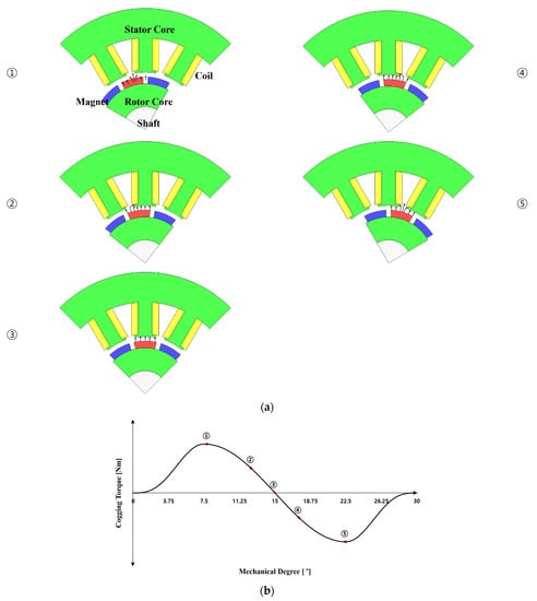
Figure 1.
Cogging torque generation mechanism (a) distribution of magnetomotive force due to permanent magnet rotation of motor (①–⑤ timeline) (b) cogging torque due to permanent magnet rotation of motor.
Three-phase motors can be initially start-up by generating a rotating magnetic field. However, in the case of single-phase BLDC motor, when the poles and slots are symmetrically designed as shown in Figure 2, the rotor is aligned at the position where the force is balanced, so even if it is excited, the initial start is unstable. Therefore, it is common to design the shape of the stator or rotor asymmetrically in order to align the initial rotor position to the position where torque can be generated. However, design to minimize cogging torque that torque and efficiency maintain aim is essential in case of if it is designed stator (or rotor) asymmetrical. This is because, due to the change in air-gap energy distribution as shown in the Equations (1)–(7), important characteristics of the motor such as torque, cogging torque, efficiency, and so forth are affected.
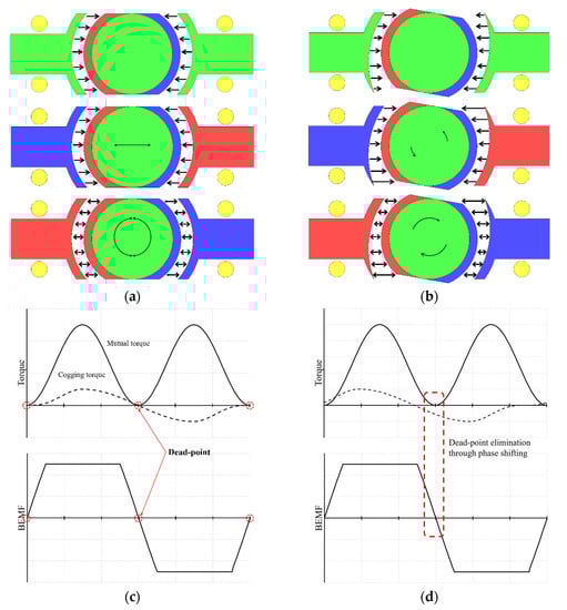
Figure 2.
Torque mechanism of single-phase BLDC motor symmetry and asymmetric air-gap (a) symmetrical air-gap (b) asymmetrical air-gap (c) dead-point for symmetry air-gap of single-phase BLDC motor (d) dead-point for asymmetric air-gap of single phase BLDC motor.
3. Specification of Single-Phase BLDC Motor and Reduction Method of Cogging Torque
The Table 1 lists the specifications of a single-phase BLDC motor and Figure 3 presents the shape of the motor. The ratio of the pole and slot in a single-phase BLDC motor should be 1:1. Therefore, a structure of eight poles and eight slots was selected to secure sufficient winding space and efficiency. The size and material were selected considering the application to a ventilation system and the unit cost of pro-duction.

Table 1.
Specifications of the single-phase BLDC motor.
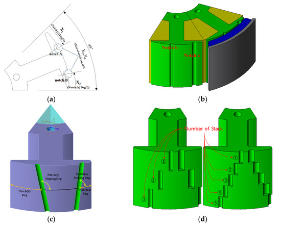
Figure 3.
Shape of sloping notch model and step-sloping notch model (a) design variables and cross section of stator of earlier model (b) sloping notch model (c) step-sloping notch model.
The cogging torque is the amount of energy variations according to the amount of rotor rotation and can be expressed using (1).
is the cogging torque, is the magnetic energy of the machine, and is the position angle of the rotor:
For the surface permanent magnet type of the BLDC, most of the energy changes occur on the air-gap part. Therefore, only the energy on the air-gap part is considered when calculating the cogging torque. The air-gap energy is expressed as (2), and was calculated from the air-gap magnetomotive force function and air-gap permeance function as follows:
where is the length of the air-gap; and is the permeability of a vacuum. In addition, is the flux density function and is the relative air-gap permeance function.
is the stack length. and can be calculated using a Fourier series expansion used in (3) as follows:
where is the number of stator slots, is the number of rotor poles and is the least common multiple of and , which affects the frequency component, , by the orthogonality of the trigonometric functions. Therefore, the air-gap energy obtained by substituting (4) and (5) for (3) can be expressed as follows:
The final cogging torque can be represented as (6) by differentiating the air-gap energy obtained from (7) according to (1) with the rotation angle of the rotor.
If the notch is applied to the stator teeth, the shape changes, and as the number of effective slots (the sum of the actual slots number and notches number) changes, the value, which is a relative air gap function. Therefore, when the notch will apply to the stator teeth so that can design to reducing cogging torque. In addition, if the space of the stator shoe is sufficient, two or more notches can be applied. The sloping notches have shaped an oblique structure along the stacking direction as shown Figure 3c unlike existing models of parallel along the stacking direction. When application an asymmetrical stator shape, it is most effective to comprise the application of the notch asymmetrically [9]. Moreover, it is more effective to reduce the cogging torque by asymmetrically different sloping notches angles, respectively. Therefore, applying the sloping notch is clearly different from the existing skewed model.
We need as many molds as the position of the notch changes depending on the characteristic that the position of the notch changes according to the height for manufacture the stator core applied sloping notches. That means that among the reasons for using the notches for the cogging torque reduction methods, meritless the cost reduction and ease of manufacturing, so it cannot be put to practical use. Therefore, in order to overcome the disadvantages, we try to apply the step-sloping notch method that applies the notch at different angles for each regular stacking section as shown in Figure 3d. The number of molds required for manufacturing varies according to Number of stack (NoS), so the fewer the NoS, the better advantageous. So, it is important to determine the fewest NoS that can minimize the cogging torque and satisfying the specifications.
4. Cogging Torque Reduction Method Using Step-Sloping Notches
4.1. Optimization of the Step-Sloping Notch Geometry to Minimize the Cogging Torque
Characteristic analysis of a single-phase BLDC motor was performed using finite element analysis. At this point, the position of the notches varies along the stacking direction. Accordingly, it must be analyzed by 3D modeling, which takes more time to analyze a single model than 2D-FEA. Therefore, it is virtually impossible to compare after analyzing all the combinations according to the number and range of variables, such as the slope degree, size, and position of notches, suitable for minimizing the cogging torque using an optimization technique.
Figure 4 shows the process of performing the optimal design of the proposed model. The method of finding the sample points is called the Design of Experiments (DOE). The goal is to extract the points that can achieve the optimal effects with a minimum number without overlapping according to the number and range of variables. Figure 5 shows the various DOEs and their corresponding deployment of experimental points. The objective function for optimization is cogging torque minimization. Torque and efficiency are important characteristics that affect the performance, so they need to be set as constraints. Various methods of DOE are available, and in this paper, among general sampling methods, the sampling point was found using an Orthogonal Array (OA) method. The larger the number of samples, the better the optimization results, but more analysis time is required. Therefore, finding an appropriate number of sampling points is the important part of the optimization process. Basically, the combination is taken to three-levels (three values as minimum, middle, and maximum, depending on the variable range), as shown in Figure 5a. In this paper, 63 sampling points were extracted and analyzed by FEA. The shape design was optimized to analyze the sample points found in DOE, producing metamodels using the results, and the optimal design point was found using an optimization technique. Metamodels use the kriging method, which is a method of direct passing the values used to make a model. The generated metamodels take the place of a characteristic analysis solver. The metamodels takes little time to obtain the result for the input. The genetic algorithm was used to find and optimize the optimal points of the design variables, and the results were then examined by FEA.
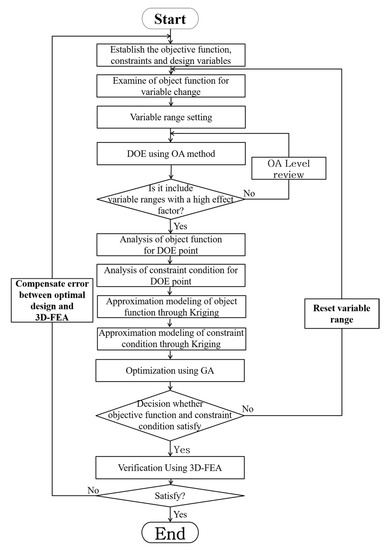
Figure 4.
Flow chart of optimal design.
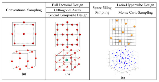
Figure 5.
Arrangement method of experiment points according to DOE’s technique (a) 3 level (b) 5 level (c) random.
4.2. OA Level Settings for DOE
Method of DOE is varied number of combinations in accordance with design variables and ranges. We should be taken a sample by experiments and simulations for DOE analysis first. We can get better optimization results as the number of samples more increases, but it requires more time to analyze the samples. Therefore, it is necessary to select and the appropriate number of samplings as applicable the spare time and circumstances. In general, the combination selects in three levels as shown Figure 5. However, it is better to include the range of a variable with an influential if it is prehensible the tendency according to the change in the range of the variable. Therefore, first, one notch was applied as shown in Figure 6 to analyze the influence of the notch, and the results are shown in Table 2. Figure 7 shows the trend for the part of the results that includes the two point where the cogging torque is minimum. It can be seen that the cogging torque waveform of the one notch model changes predictably according to the position of the notch, and the points with the smallest cogging torque were 7° and 40°. However, these points are not included in the 3-level combination of the OA level, and the approximate point is included in the 5-level combination. Therefore, the OA Level of the DOE was set to 5 levels.
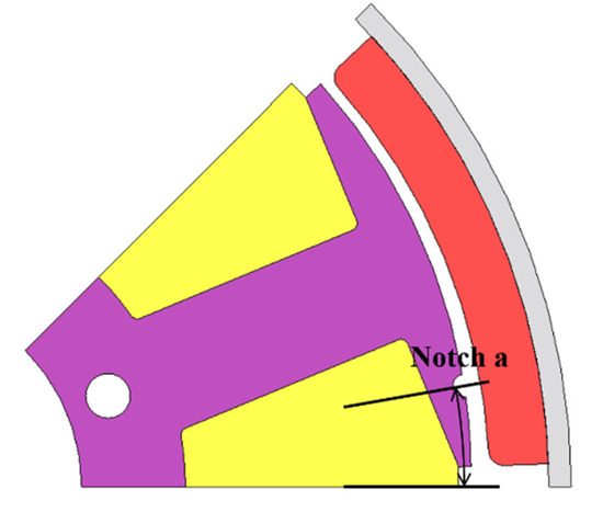
Figure 6.
1 notch model for trend analysis.
Table 2.
Cogging torque result of 1 notch model.
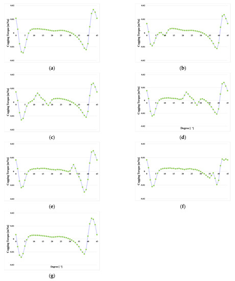
Figure 7.
Trend analysis of cogging torque for notch position (a) 2°; (b) 7°; (c) 15°; (d) 25°; (e) 35°; (f) 40°; (g) 43°.
A DOE including the optimal point was performed. Table 3 shows the sampling results for the 63 samples and the finite element analysis results for each sample for verification. Results for cogging torque, efficiency, and torque should be analyzed for each sample. The cogging torque is a no-load analysis. So, efficiency and torque are load analysis with current analyses are needed to extract the results for one sample and 3D analysis must be performed due to the notch shape at different locations for each stack. As a result, it took approximately 1 h to analyze each model (There may be some differences depending on the condition settings such as the element division method and step division of the analysis time period). Because it takes so much time, it is advantageous to use an optimization technique if there is not enough time to analyze all the desired cases.
Table 3.
Specifications of the single-phase BLDC motor.
4.3. Design Variables and Objective Functions
Figure 3 presents the design variables for minimizing the cogging torque; the size, position, and sloping angle of the notches were determined as design variables (X1∼X7).
The notches size variable range (X2, X4) was selected in consideration of the thickness of the stator shoe. If the size of the notches is too large, an abnormal hole may be drilled near the end of the shoe, so the maximum value was selected as 3 mm. The minimum value was selected as 0.5 mm, which is a realizable size while affecting the cogging torque. The position of notches for variable range (X1, X3) is the value at the midpoint of the stacking height as shown Figure 3a,c. The angle per slot is 45° and it is set to 20° considering that two notches are applied. The sloping of notches for variable range(X5, X6) was selected as the maximum value of 10° and the minimum value of −10°. Because it is an angle that does not overlap each other by encroaching on area when the position variables X1 and X3 are intermediate positions based on 10°.
Therefore, the range of design variables for optimal design is as follows:
| - Design variables | ||||
| · 2° | ≤ | X1 (Notch (a) Angle) | ≤ | 20° |
| · 0.5 mm | ≤ | X2 (Notch (a) Size) | ≤ | 3 mm |
| · 2° | ≤ | X3 (Notch (b) Angle) | ≤ | 20° |
| · 0.5 mm | ≤ | X4 (Notch (b) Size) | ≤ | 3 mm |
| · −10° | ≤ | X5 (Notch (a) Sloping Angle) | ≤ | 10° |
| · −10° | ≤ | X6 (Notch (b) Sloping Angle) | ≤ | 10° |
| · 1 | ≤ | X7 (Layer of Stek) | ≤ | 15 |
The objective function aims to minimize the cogging torque and the constraints were set considering the design specifications as follows:
- −
- Objective functionReduce the cogging torque
- −
- Constraint’s conditionEfficiency ≥ 70%Torque ≥ 390 mN·m
Constraints were set to 390 mN·m ≤ T for torque and 70% ≤ η for efficiency according to the design specifications as shown in Table 1 in consideration of the errors between simulation and experiments inasmuch as torque and efficiency are critical characteristics which affects performance.
5. Optimal Design Results
Figure 8 shows the convergence of the objective function and the constraints for the optimization simulation of each design variable. Table 4 lists the optimal design results using the genetic algorithm. In addition, Figure 9 shows the stator shape for the optimal results.
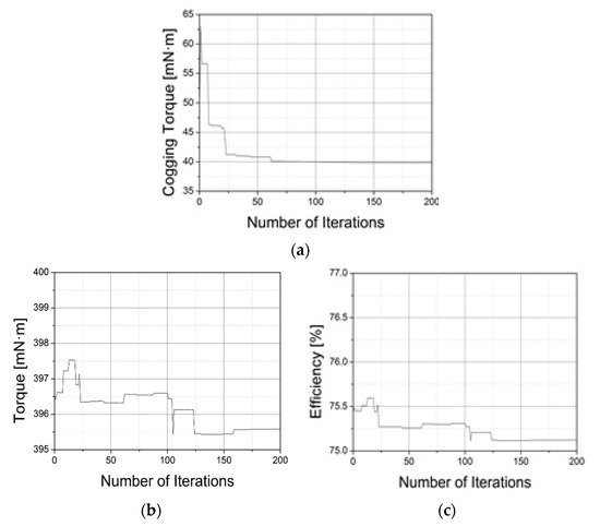
Figure 8.
Convergence progress of the objective functions and constraints (a) cogging torque (b) torque (c) efficiency.
Table 4.
Results of optimal design.
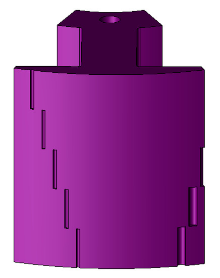
Figure 9.
Optimal design model applied step-sloping notch.
As a result, of the optimal design, the size and position angle of notch (a) were 2° and 1.2162 mm, respectively, and those of notch (b) were 11.0925° and 0.5 mm, respectively. The FEA was used to verify the optimal design results. The results of cogging torque analysis were 43 mN·m for the cogging torque of the 2 notches model, and 22 mN·m for that of the optimum model, which was similar to the optimal design results. In addition, the efficiency and torque met the design specifications while reducing the cogging torque by 51% compared to the two notch model.
Moreover, the result of the constraint on the optimization result needs to be confirmed. Figure 10 analyzes the characteristics of the optimization model using FEA.
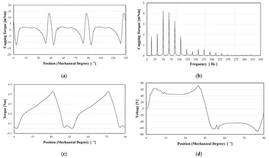
Figure 10.
Optimal design results (a) cogging torque (b) FFT of cogging torque (c) torque (d) voltage.
6. Conclusions
This paper reported a method to reduce the cogging torque of a single-phase BLDC motor. The earlier model had two notches with a straight along the stacking direction of asymmetric positions and sizes to reduce the cogging torque. The step-sloping notch model has the advantage of having a skew effect by constructing a slope along the stacking direction differently from the earlier model.
Cogging torque optimization was performed using the size, position, and sloping angle of the notches as variables to demonstrate the cogging torque reduction effect of the proposed step-sloping notch method. The results of the optimization were verified by FEA and compared with the straight two notch model. As a result, the cogging torque was reduced by more than 50% compared to the earlier model, demonstrating the excellence of the step-sloping notch method.
Author Contributions
Conceptualization, D.-k.K.; methodology, Y.-w.P.; software, Y.-w.P.; validation, D.-k.K. and J.-s.K.; formal analysis, Y.-w.P.; investigation, Y.-w.P. and J.-s.K.; resources, D.-k.K.; data curation, Y.-w.P. and J.-s.K.; writing—original draft preparation, Y.-w.P. and D.-k.K.; writing—review and editing, D.-k.K.; visualization, Y.-w.P.; supervision, D.-k.K.; project administration, D.-k.K.; funding acquisition, D.-k.K. All authors have read and agreed to the published version of the manuscript.
Funding
This research received no external funding.
Institutional Review Board Statement
Not applicable.
Informed Consent Statement
Not applicable.
Data Availability Statement
Not applicable.
Acknowledgments
This work was supported by the Gwangju Jeonnam local Energy Cluster Human Resources Development of the Korea Institute of Energy Technology Evaluation and Planning (KETEP) grant funded by the Korea government Ministry of Knowledge Economy (No. 20214000000560).
Conflicts of Interest
The authors declare no conflict of interest.
References
- Rahman, M.A.; Little, T.A. Dynamic performance analysis of permanent magnet synchronous motors. IEEE Trans. Power Appar. Syst. 1984, PAS-103, 1277–1282. [Google Scholar] [CrossRef]
- Fazil, M.; Rajagopal, K.R. A novel air-gap profile of single-phase permanent-magnet brushless dc motor for starting torque improvement and cogging torque reduction. IEEE Trans. Magn. 2010, 46, 3928–3932. [Google Scholar] [CrossRef]
- Chung, D.W.; You, Y.M. Cogging torque reduction in permanent-magnet brushless generators for small wind turbines. J. Magn. 2015, 20, 176–185. [Google Scholar] [CrossRef]
- Bentouati, S.; Zhu, Z.Q.; Howe, D. Influence of design parameters on the starting torque of a single-phase PM brushless DC motor. IEEE Trans. Magn. 2000, 36, 3533–3536. [Google Scholar] [CrossRef]
- Kang, G.H.; Son, Y.D.; Kim, G.T.; Hur, J. A novel cogging torque reduction method for interior-type permanent-magnet motor. IEEE Trans. Ind. Appl. 2009, 45, 161–167. [Google Scholar] [CrossRef]
- Schlensok, C.; Gracia, M.H.; Hameyer, K. Combined numerical and analytical method for geometry optimization of a PM motor. IEEE Trans. Magn. 2006, 42, 1211–1214. [Google Scholar] [CrossRef]
- Park, Y.U.; Cho, J.H.; Kim, D.K. Cogging torque reduction of single-phase brushless DC motor with a tapered air-gap using optimizing notch size and position. IEEE Trans. Ind. Appl. 2015, 51, 4455–4463. [Google Scholar] [CrossRef]
- Park, Y.U.; So, J.Y.; Woo, K.I.; Kim, D.K. Cogging Torque Reduction Method of a Single-Phase BLDC Motor using Asymmetric Sloping Notch. Trans. Korean Inst. Electr. Eng. 2017, 66, 1569–1574. [Google Scholar]
- Park, Y.U.; So, J.Y.; Chung, D.H.; Yoo, Y.M.; Cho, J.H.; Ahn, K.S.; Kim, D.K. Optimal design of stator shape for cogging torque reduction of single-phase BLDC motor. Trans. Korean Inst. Electr. Eng. 2013, 62, 1528–1534. [Google Scholar] [CrossRef][Green Version]


Publisher’s Note: MDPI stays neutral with regard to jurisdictional claims in published maps and institutional affiliations. |
© 2021 by the authors. Licensee MDPI, Basel, Switzerland. This article is an open access article distributed under the terms and conditions of the Creative Commons Attribution (CC BY) license (https://creativecommons.org/licenses/by/4.0/).