Abstract
In the present work, a methodology that allows optimizing the permanent magnet synchronous generator (PMSG) design by establishing limit values of magnet radius and length that maximize efficiency for the nominal parameters of the wind turbine is developed. The methodology consists of two fundamental models. One model calculates the generator parameters from the radius of the magnet base, and the other optimization model determines two optimum generators according to the optimization criteria of maximum efficiency and maximum efficiency with minimum weight starting from the axial length and the radius of the magnet base. For the optimization, the numerical method of the golden section was used. The model was validated from a 10 kW PMSG and the results of two optimum generators are presented according to the optimization criteria. In addition, when the obtained results are compared with the reference electric generator, an increase in efficiency of 1.15% and 0.81% and a reduction in weight of 30.79% and 39.15% of the optimized generators are obtained for maximum efficiency and minimum weight, respectively. Intermediate options between the maximum efficiency generator and the minimum weight generator allows for the selection of the optimum dimensioning for the electric generator as a function of the parameters from the wind turbine design.
1. Introduction
The permanent magnet synchronous generator (PMSG) used for wind systems should have low weight [1,2] and high efficiency [3,4]; therefore, the PMGS geometry has been modified to reduce the volume of the materials for its production [4,5,6,7,8].
For the PMSG optimization, the magnetic model and the equivalent circuit are generally used to obtain the parameters at their nominal operation point [5,7,8,9,10]. To solve these models the finite analysis methods, genetic algorithms, or analytical calculations are used [9,11,12]; however, the differences in the results from these methods are minimal. Some researchers also consider the properties of the materials for the PMGS construction and its geometry [6,13] and then their theory is validated with experimental prototypes [8,9,14,15].
The input parameters for the electric generator dimensioning are usually obtained from the output parameters of the wind turbine rotor design [15,16,17], which are also obtained from the statistical model of Weibull or Raleigh [11,15,18].
The statistical models are also used for the estimation of the annual energy production (AEP) [11,12,19] and then the energy produced by the wind turbine at each wind speed is obtained from the simulation of the wind turbine rotor coupled to the PMSG [16,17,19], including the data of the maintenance and the emplacement.
Obtaining the highest AEP from the emplacement is commonly a criterion for wind turbine optimization for the fastest economic recovery [11,12,18,19]; H. Li, z. Chen et al., 2009 [12] optimized a PMSG design using a genetic algorithm and compared it to a 500 kW generator to demonstrate the effectiveness of the optimization, the wind turbine rotor dimension, and the AEP.
Another criterion used for the PMSG optimization is the reduction of the cogging to use the low wind speeds [8,10,14,20]; Potgieter et al., 2012 [7] proposed a method to identify the low pair of the cogging region through the variation of the magnet geometry of the PMSG.
The reduction of the PMSG weight is also an optimization criterion for its application on wind turbines to minimize the fixed and variable losses and to maximize the PMSG efficiency [21,22,23,24]; Chen et al., 2021 [24] simulated a cross-flow PMSG to reduce the volume of the magnetic poles using the finite element method and the magnetic equivalent circuit. In this work, they reported the yield improvement of the machine with a low volume of the magnetic poles and high-power density.
The relation of the weight of the PMSG with the cost is another criterion used for the wind turbines design where the goal is to reduce the energy and the wind turbine cost [16,23,25,26]; as Machado et al., 2016 [16], reported a multi-disciplinary optimization (MDO) of 55 kW PMSG to reduce the cost. This work included the cost models and the power converter losses and they obtained three options which simplified to one when the phase angle was considered in the power converter [16].
Maximizing the PMSG efficiency is another criterion used for wind turbines optimization [10,16,22,27,28]; with this goal, Tapia et al. [27] modified the stator geometry and obtained the PMSG losses with the equivalent circuit which was validated with the construction of a 10 kW prototype.
Generally, the research works related to the PMSG optimization for wind turbines have obtained only a design as the result of the criteria used for the optimization [14,24,25,29,30]. This contribution aims to develop an optimization methodology for the PMSG dimensioning to be coupled to wind turbines regarding the wind resource, the turbine rotor, and the power converter; also the PMSG dimensioning involves two optimization criteria where for each radius of the magnet base (Rbi), the generator was optimized based on maximum efficiency and later the obtained optimal generator for maximum efficiency that had the minimum weight was searched but the optimization process based on minimum weight was not carried out. Finally, two designs of the electric generator were obtained and compared with a commercial prototype of 10 kW used as reference.
In contrast with the reviewed previous works, the present study establishes a procedure that allows one to obtain in a practical way dimension of an optimal PMSG for maximum efficiency with a method that defines the limits of maximum efficiency and minimum weight for maximum efficiency. This avoids PMSG solutions with greater weight and lower efficiencies and gives design options that guarantee the combination of both requirements depending on the design parameters of the wind turbine.
2. Materials and Methods
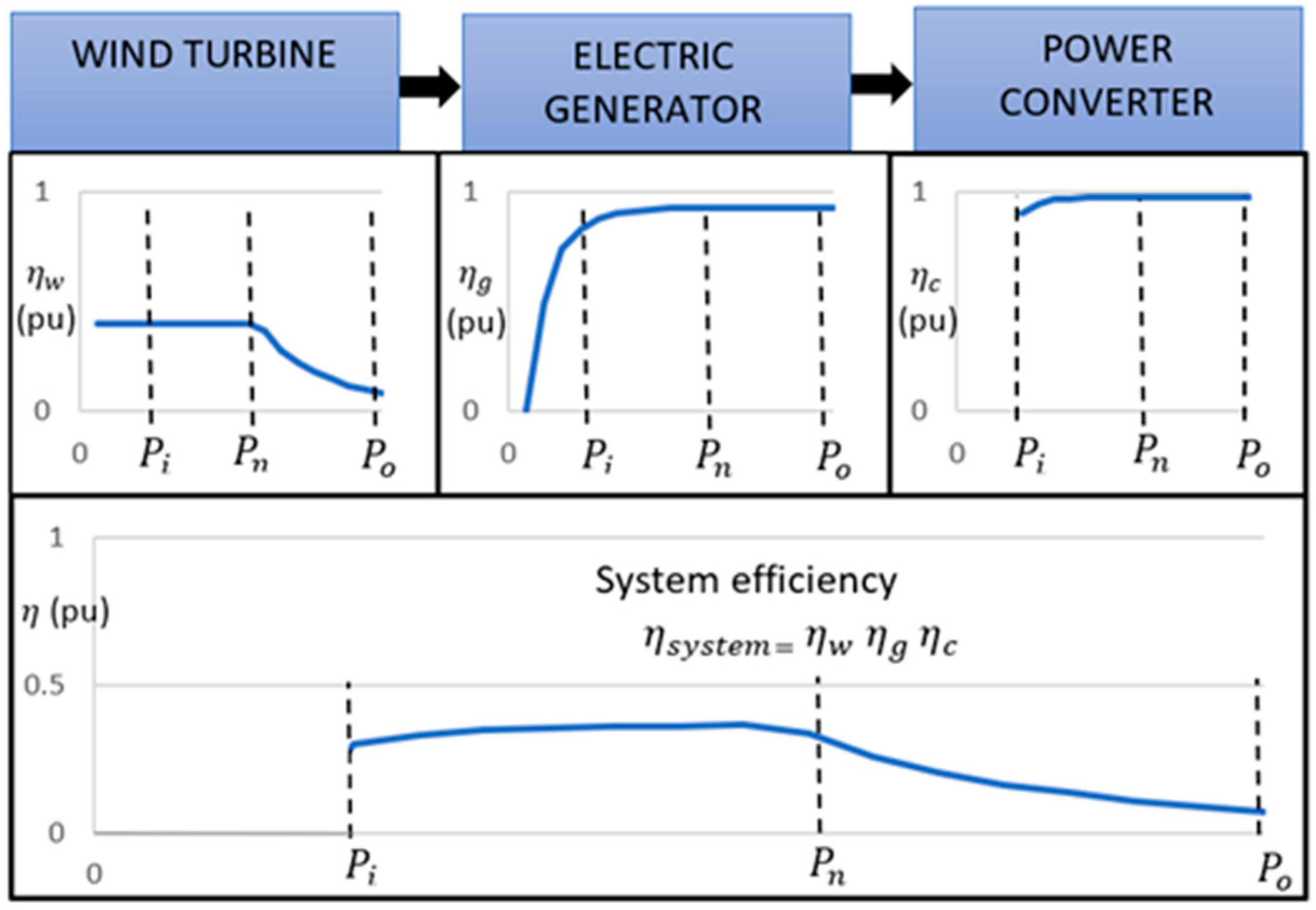
The output power of a wind turbine depends on the efficiency of each component (Figure 1). To maximize the efficiency of the system, the efficiency of the PMSG for wind turbines must be the maximum in the operation range which depends on initial power (pin) and the output power (pout).
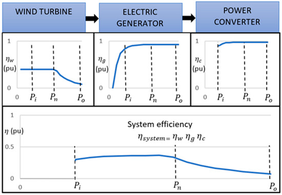
Figure 1.
Efficiencies of the direct drive wind turbines components (obtained from own simulations).
2.1. Mechanical Power
The maximum mechanical power used by the turbine rotor from the available wind is given in Equation (1) [16].
where Cp is the power coefficient, ρ is the air density, A is the cross-section area of the turbine rotor, v is the wind speed, Tm is the mechanical torque from the turbine rotor to the PMSG shaft, and ωm is the angular speed of the shaft.
2.2. Design Conditions
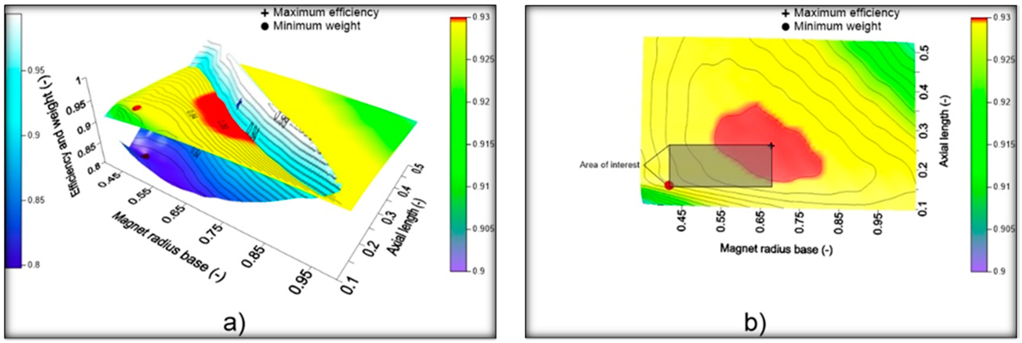
The maximum efficiency and the lowest weight of the PMGS are generally the criteria for the PMSG design for wind turbines applications. Figure 2a shows the typical behavior of the weight PMSG increases for lower values of Rbimin and Lmin and similar efficiencies with lower weights can be obtained at lower values of de Rbimax y Lmax to higher values, as Figure 2b shows. These limits also imply an area that represents the radio options and the possible lengths for the PMSG design for direct shaft wind turbines.
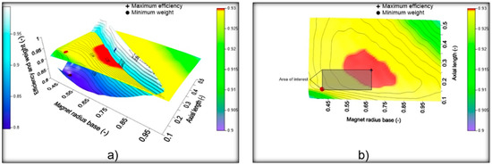
Figure 2.
(a) Efficiencies behavior and weights of the electric generator with different dimensions. Area of the analysis delimited by the maximums and minimums points; (b) Interest area from the superior view (obtained from own simulations).
2.3. PMSG Design
The fundamental equations used for the PMSG design were obtained from the analytic analysis of the magnetic circuit of the permanent magnet synchronous motor [31]. These equations are resumed as follows:
2.4. PMGS Efficiency
The PMSG efficiency (η) depends on the process losses from the mechanical power conversion to electrical power as in Equation (2) [15,17,27,28,31].
where Pmec is the mechanical power from the turbine rotor and Pelec is the electrical power which depends on the copper losses Pcu, the iron core losses PFe, and other losses Po.
2.5. Copper Losses
The copper losses depend on the ohmic resistance (Rph) of a single-phase coil, the phase current (Iph) through the conductor, and the number of phases of the PMSG (Nph) [17,18,27,29,31] as in Equation (3).
2.6. Iron Core Losses
The iron losses depend on the electrical properties and the stator volume (Volest) [13,15,17,18,22,23,31], as in Equation (4).
where fe is the electrical frequency, Bm is the maximum flux density of the iron; Kh, ke, and Kc are the losses constants due to the properties of the iron alloy known as hysteresis loss, Eddy current loss, and coupling loss respectively [13,17,22,32]. The Volest of the radial flow PMSG was calculated with Equation (5)
where Rso is the stator outer radius, Rsi is the stator inner radius, Ns is the number of splines, As is the spline area, Kst is the stacking factor, and L is the PMSG axial length.
2.7. Other Losses
These losses involve the mechanical losses due to the bearing friction and the internal turbulence produced by the rotor of the electric generator. The Eddy currents losses in the rotor core are not considered because they are subjected to a continuous magnetic field [9,18,21].
2.8. Geometric Parameters of the PMSG
The rotor outer radius (Rer) is determined by Rbi and the magnet height (Ai) as Equation (6):
The inner stator radius (Rsi) is determined by Rer and the air gap (g) as Equation (7):
The outer stator radius (Rso) is calculated by Rsi, the total spline depth (ds), and the width of the stator back iron (wbi) as Equation (8):
2.9. Electrical Parameters
To determine the electrical parameters these were the considerations: a unity power factor, a parallel magnet surface to the inner stator surface, a square wave shape of the electrical sign which generates a pair of poles, and then the electromotive force (Erms) is equal to the maximum (Emax) as Equation (9)
where L is the axial length of the PMSG (which is the same for the rotor and the stator) Rro is the rotor outer radius, Bg is the field density of the airgap, Nm is the number of magnetic poles, ns is the number of turns per slot, Nspp is the number of slots per poles per phase, and Kd, Kp, Ks are the engine characteristic constants [31].
The PMSG current density (Is) is determined from the mechanical torque (Tm) as Equation (10).
The phase electric current (Iph) is the relation between the Is and the number of splines (Ns) and the number of the PMSG phases (Nph) as in Equation (11).
The phase voltage (Vph) is the argument of the vector calculated from the equivalent circuit of the one-phase PMSG and its phasor diagram.
Equation (13) shows the balance of the PMSG power.
2.10. Methodology Development
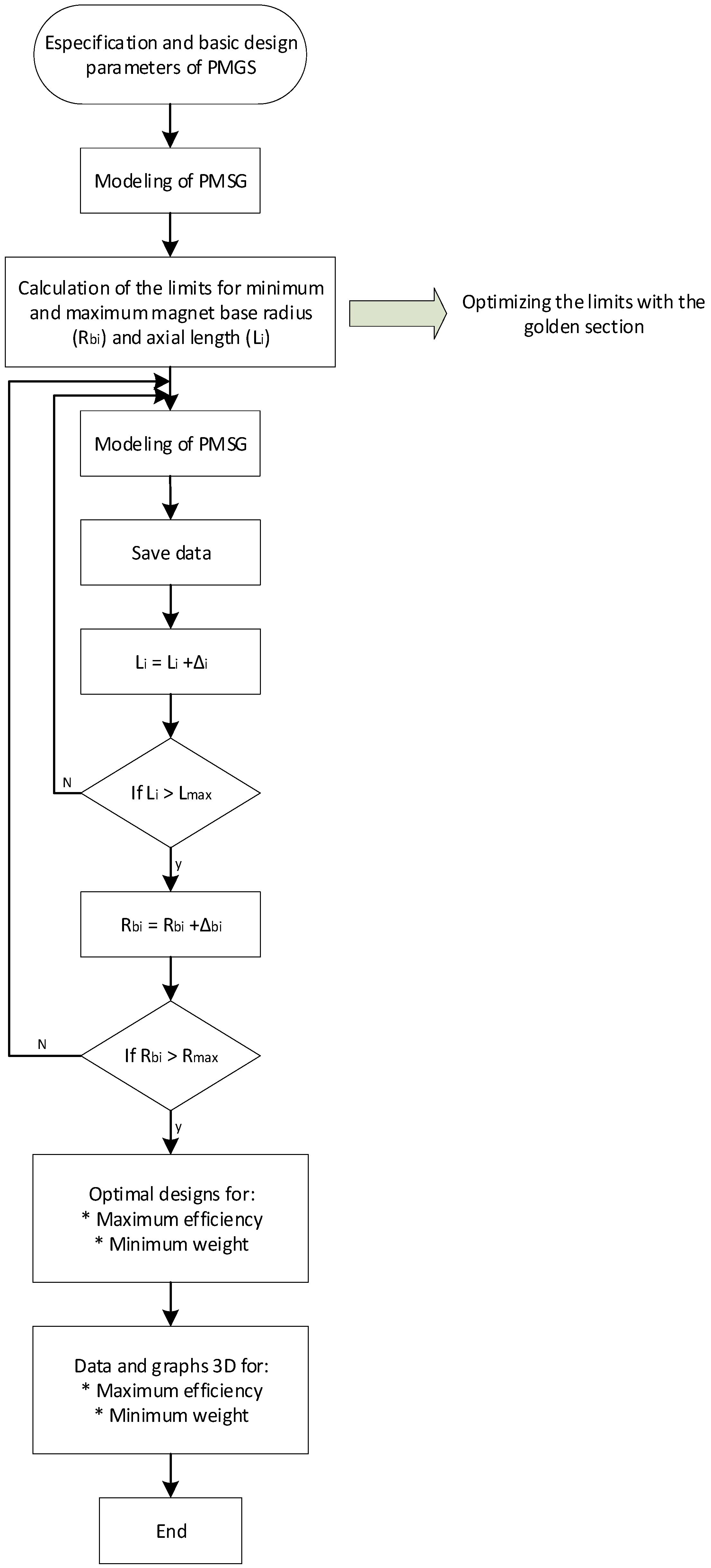
The methodology developed for the optimization is shown in the diagram of Figure 3 where the characteristics of the materials used are considered from the beginning as well as the design specifications for the PMSG (Pm, ωm, Rbimax, Rbimin, and others) which were obtained from the nominal wind speed of the turbine rotor.
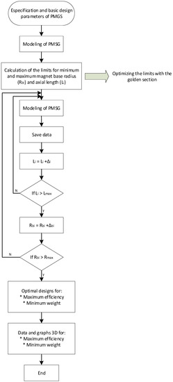
Figure 3.
General flow diagram of the PMSG optimization.
First, the PMSG parameters for each optimization criterion are determined through a simulation process, in this way the Rbi and L values for each optimization criterion that define the limits used for the implementation of the methodology are obtained using the numerical method of the golden section (Steps 1–3).
Later, an analysis is carried out within the optimization limits to present alternatives of PMSG dimensioning to obtain a better option that couples to the components of the wind turbine. Two optimal dimensioning based on each criterium and the general mapping within the limits are obtained.
Figure 4 shows the PMSG sizing procedure where the input variable Rbi is related to fixed parameters such as volume of magnets, number of poles, number of slots, number of phases, and magnetic fraction. It then calculates the height and length of the magnet that maximizes efficiency to obtain the geometry of the PMSG and to determine the output parameters such as efficiency, current, voltages, power, phase resistance, copper losses, iron losses, power density, weight, and others.
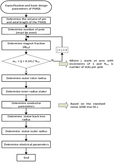
Figure 4.
Flow diagram for the dimensions of the PMGS.
Finally, the simulations of the wind turbine are carried out to determine the power and efficiency curves using the method of the reference [17] and with these curves the energy produced from the Weibull distribution that characterizes the site is determined.
3. Results and Discussion
The methodology was validated using data from a PMGS prototype as a reference to calibrate the dimensioning software. This PMSG prototype of 10 kW was designed and fabricated by a specialized company. The material considered for the stator core was the JFE50JN400, Nd-Fe-B grade 35 for the permanent magnets and copper for the coils. These values are shown in Table 1.

Table 1.
Calibration parameters for the PMSG dimensioning program.
The input fixed parameters used for the validation are shown in Table 2.
Table 2.
Fixed parameters for the PMSG design.
The proposed optimization methodology is applied and as a result, two optimal PMSG dimensioning is obtained in conformity with each optimization criterion; the fundamental parameters are compared with the reference PMSG as shown in Table 3.
Table 3.
Comparison of the results for the different simulated optimization criteria.
The optimal PMSG for maximum efficiency presented 1.06% more efficiency than that of the reference PMSG and the optimal PMSG for minimum weight showed a 0.75% increase of efficiency and a decrease of 32.1 kg of weight. For this study, the reference PMSG is out of the limits proposed by the methodology for the 3-D analysis, and therefore, it is not considered for the following analysis.
Machado et al., 2017 [16] optimized a PMSG and reported a maximum efficiency of 94.2% and a power density of 182.5 W/kg for a 50 kW commercial wind turbine; the generator efficiency increase was 2.9%.
The general graphic of the efficiency behavior for the defined limits by the geometry dimensioning of the lower weight and major efficiency is shown in Figure 5. The radius of the magnet base varies from 21 to 26 cm and the axial length from 6 to 7 cm. Figure 5 shows the geometric limits with respect to the efficiency and there is a variation of 0.4% of the efficiency.
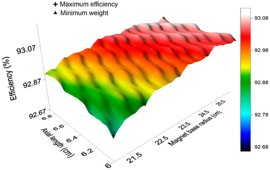
Figure 5.
PMSG efficiency behavior as a function of the design limits (obtained from own simulations).
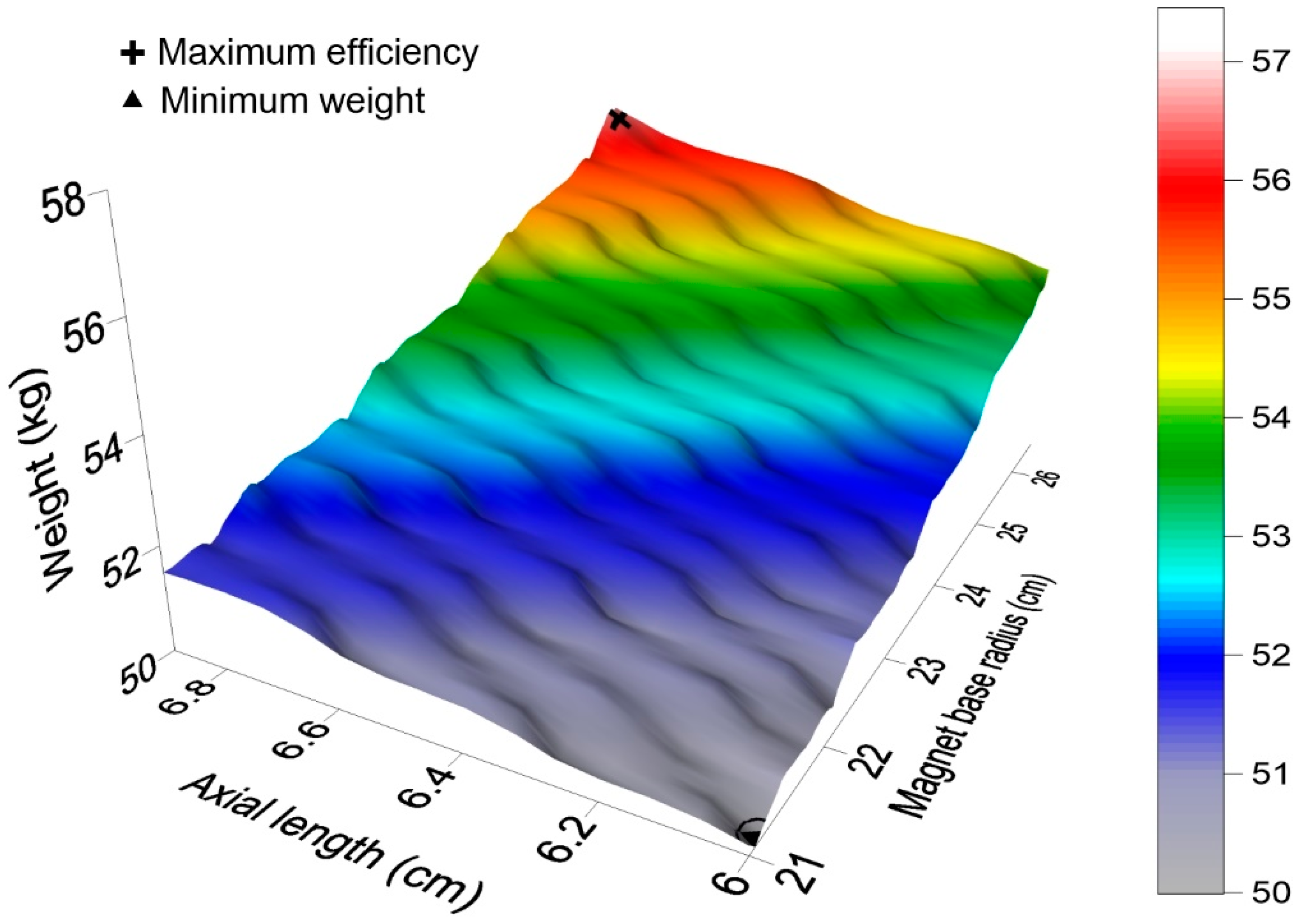
The general graphic of the weight behavior for the same limits established is shown in Figure 6. From this figure can be observed that the weight difference between the PMSG of the maximum efficiency and the PMSG of the minimum weight is 6.86 kg, which implies a difference of 12.16%.

Figure 6.
Behavior of the PMSG weight as a function of the design limits (obtained from own simulations).
The data for the coupling analysis of the optimum PMSG and the PMSG reference to the wind rotor for a specific emplacement are shown in Table 4.
Table 4.
Emplacement parameters.
The parameters of the wind rotor for a 10 kW wind turbine are shown in Table 5.
Table 5.
Wind rotor parameters.
Simulation of a Wind Turbine Using the Optimal PMSG Designs
For the coupling simulation, the power coefficient is considered constant since it is also considered that the wind rotor works with the constant specific speed, and it is the same for all simulations. It is considered that the order of variation of the voltages and powers between the PMSGS is very small compared to the order of variation of voltage and power of the converter efficiency curve and therefore its influence on the total efficiency of the system is minimal. In this way, the differences obtained are mainly caused by the PMSG.
The PMSG is simulated using the equations for the losses Equations (3) and (4), the equivalent electrical circuit model, and the power curve of a commercial inverter of the same power.
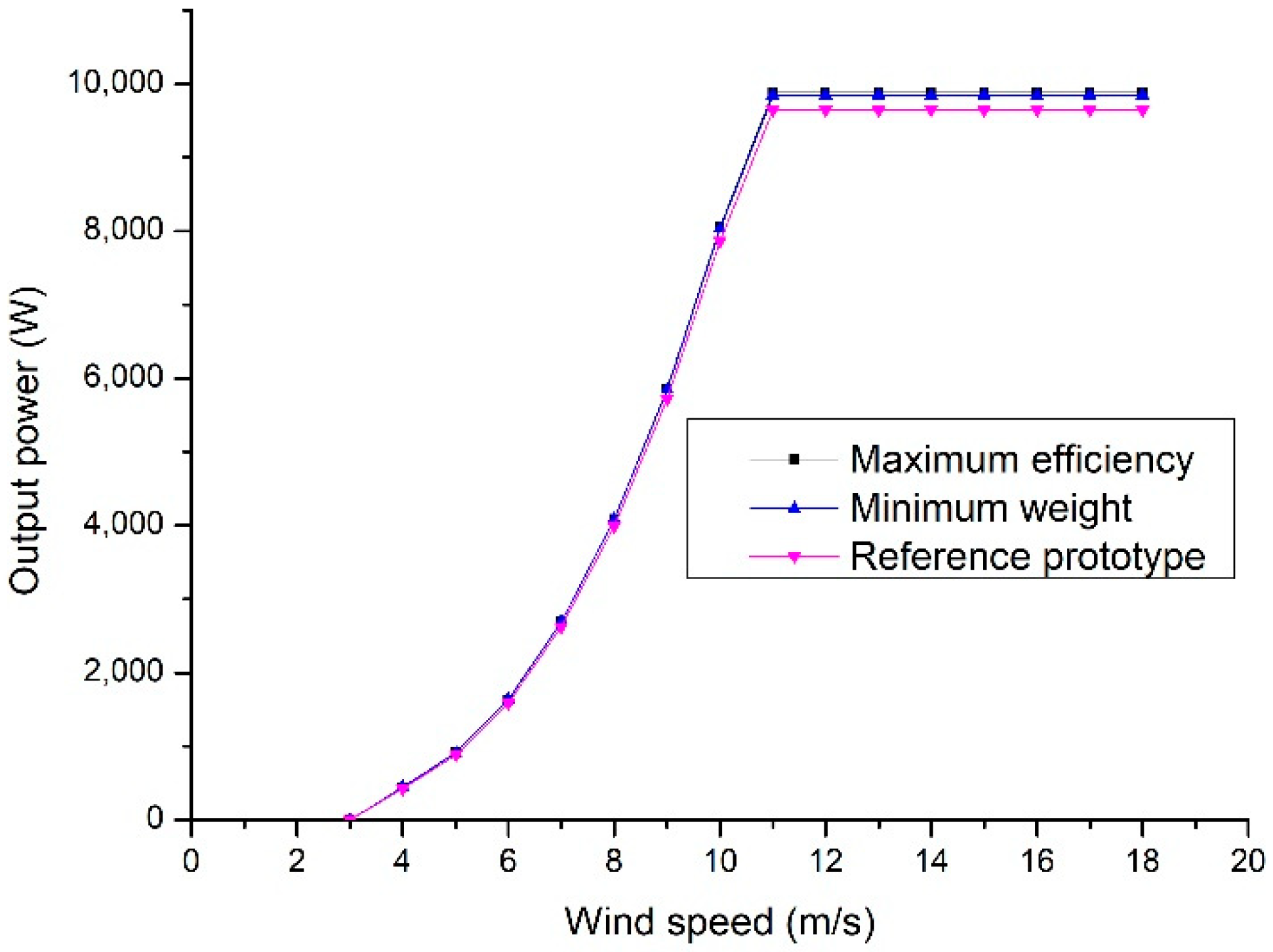
Figure 7 shows the power curves of the simulated PMSG. A nominal power increase of 2.03% for the optimum lower weight PMSG and 2.37% for the optimum maximum efficiency PMSG to the reference PMSG are observed.

Figure 7.
Power output of the analyzed PMSG.
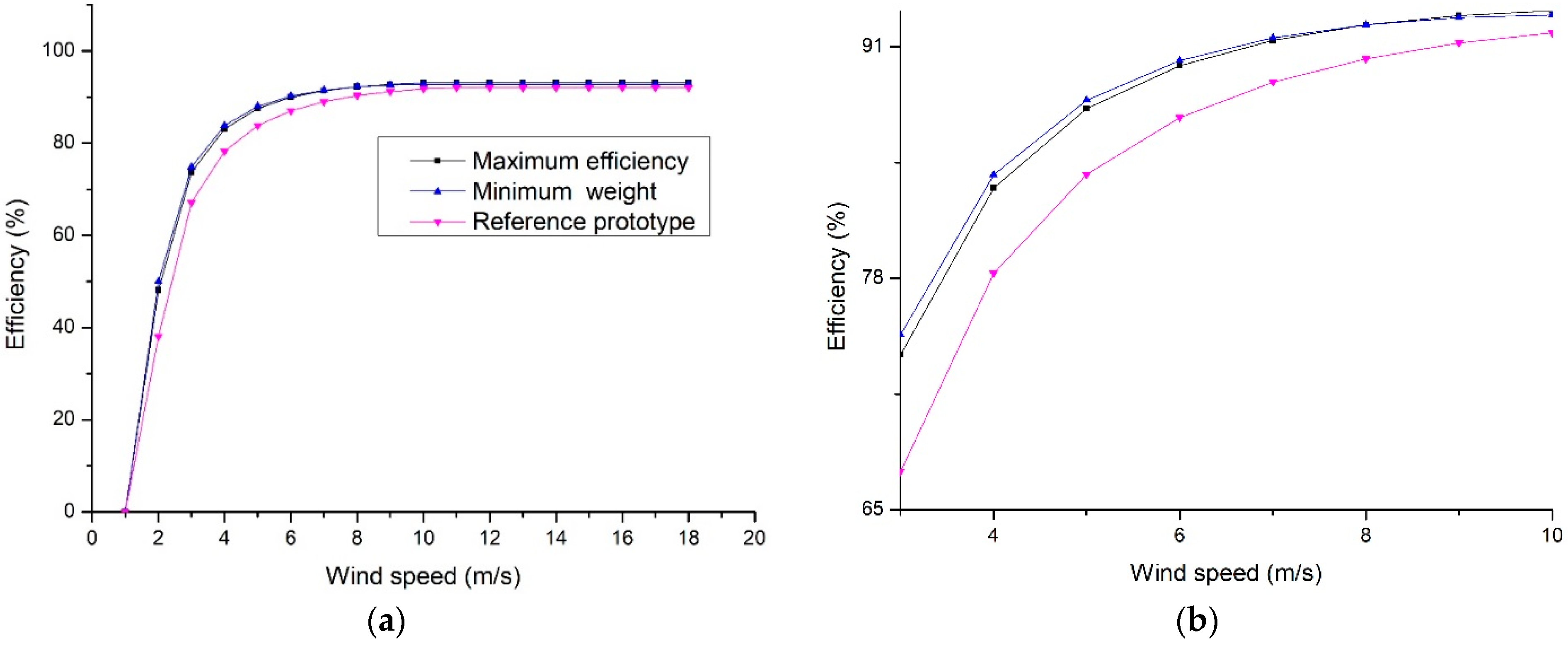
Figure 8a shows the performance of the efficiencies of each PMSG design, and Figure 8b shows the comparison of the reference generator with the optimized generators. It can be observed that from initial speed to nominal speed there is a difference of approximately 10% while at its nominal design speed this difference is 1%. This presumes an important improvement on the PMSG design for its application in wind turbines due to the improvement in the power extraction from the lower speeds as compared to the nominal wind speed.
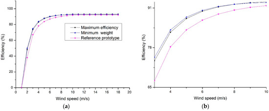
Figure 8.
(a) PMSG efficiency as a function of the wind speed; (b) Approach to the variable operating zone.
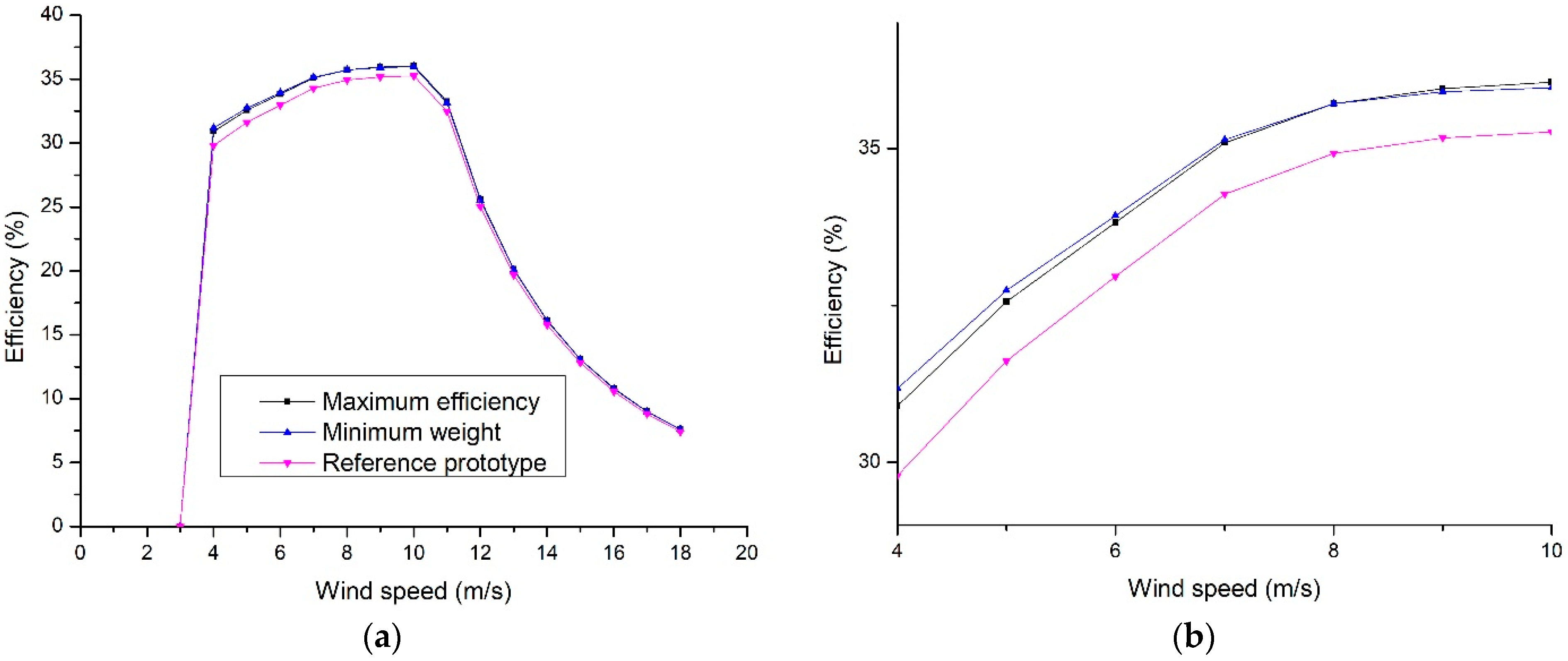
The total efficiency behavior of the wind turbine is shown in Figure 9a. This is obtained from the multiplication of their component’s efficiencies, namely generator, wind rotor, and inverter. Figure 9b showed that the efficiencies of wind turbines with the optimized PMSGs are higher than that of the reference PMSG for the nominal speed. These efficiency differences are 0.75% and 0.64% higher for the maximum efficiency optimized PMSG and the minimum weight-optimized PMSG respectively and the difference between them is 0.11%. The PMSG of minimum weight has higher efficiency for low wind velocities and therefore the energy use is improving.
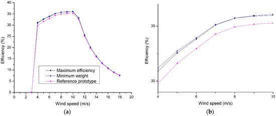
Figure 9.
(a) Total efficiency of the system; (b) Approach to the variable operating zone.
To calculate the AEP the data of Table 1 and the PMSGs power curves were used. The results in Table 6 demonstrate the possibility of obtaining a design for higher AEP as compared to that obtained from the prototype. This difference is 794 kWh, and the difference between the minimum weight-optimized PMSG and the maximum efficiency optimized PMSG is 62 kWh.
Table 6.
Annual energy production for each PMSG design.
4. Conclusions
In the current work, a method that restricts the useful dimensioning options for direct axis wind turbines to a range of magnet radius and lengths (Rbi, L) is developed. This range of Rbi and L values is limited by the points of both maximum efficiency and maximum efficiency with minimum weight, neglecting the rest of the options that imply lower efficiencies and higher weights. In this way, it is established that all the options work with maximum efficiency.
The application of this methodology demonstrated the viability of maximizing the efficiency, reducing the PMSG weight, and improving the AEP and the wind turbines yield at all working speeds of their power curve.
The methodology was validated with a 10 kW wind turbine and two optimum generators were obtained. The results indicated that when they were compared with the reference electric generator results, an increase in efficiency of 1.15% and 0.81% and a reduction in weight of 30.79% and 39.15% of the optimized generators were obtained for maximum efficiency and for minimum weight, respectively. The AEP was estimated from simulation for each generator design and the generator designed for the minimum weight showed higher efficiency compared to the reference generator and the highest energy production was obtained with the design of the generator of maximum efficiency. It is important to highlight that a greater efficiency value was obtained in the region of low wind velocities of the system efficiency curve for the case of the PMSG with minimum weight.
Author Contributions
Conceptualization, J.A.E.S., O.L.D., G.I.D., J.E.C.D., A.V.A., Q.H.E., J.P.E., L.V., G.H.G., R.D.P. and A.-J.P.-M.; methodology, J.A.E.S., O.L.D., G.I.D., J.E.C.D., A.V.A., Q.H.E., J.P.E., L.V., G.H.G., R.D.P. and A.-J.P.-M.; writing—original draft preparation, J.A.E.S., O.L.D., G.I.D., J.E.C.D., A.V.A., Q.H.E., J.P.E., L.V., G.H.G., R.D.P. and A.-J.P.-M.; writing—review and editing, J.A.E.S., O.L.D., G.I.D., J.E.C.D., A.V.A., Q.H.E., J.P.E., L.V., G.H.G., R.D.P. and A.-J.P.-M. All authors have read and agreed to the published version of the manuscript.
Funding
This research received no external funding.
Institutional Review Board Statement
Not applicable.
Informed Consent Statement
Not applicable.
Data Availability Statement
The data presented in this study are available on request from the corresponding author.
Acknowledgments
The authors would like to thank CONACYT and the IIER of UNICACH for their support of the PhD project “Optimization of low power wind turbines”.
Conflicts of Interest
The authors declare no conflict of interest.
References
- Leung, D.Y.; Yang, Y. Wind Energy Development and Its Environmental Impact: A Review. Renew. Sustain. Energy Rev. 2012, 16, 1031–1039. [Google Scholar] [CrossRef]
- Bang, D.; Polinder, H.; Shrestha, G.; Ferreira, J.A. Review of Generator Systems for Direct-Drive Wind Turbines. In Proceedings of the European Wind Energy Conference and Exhibition, Brussels, Belgium, 31 March–3 April 2008; Volume 31, pp. 1–11. Available online: https://www.semanticscholar.org/paper/Review-of-Generator-Systems-for-Direct-Drive-Wind-Bang-Polinder/f69a9f66bfee76f0bb2f3d34a8d6ae20697c0bf4 (accessed on 29 September 2021).
- Saidur, R.; Rahim, N.; Islam, M.; Solangi, K. Environmental Impact of Wind Energy. Renew. Sustain. Energy Rev. 2011, 15, 2423–2430. [Google Scholar] [CrossRef]
- Bang, D.; Polinder, H.; Shrestha, G.; Ferreira, J.A. Comparative Design of Radial and Transverse Flux PM Generators for Direct-Drive Wind Turbines. In Proceedings of the 2008 18th International Conference on Electrical Machines, Vilamoura, Portugal, 6–9 September 2008; IEEE: Piscataway, NJ, USA, 2008; pp. 1–6. Available online: https://www.semanticscholar.org/paper/Comparative-design-of-radial-and-transverse-flux-PM-Bang-Polinder/a8ccb7f1f06860e0f98ab86f1b7aff92798c0c1d (accessed on 29 September 2021).
- Xu, Y.; Maki, N.; Izumi, M. Performance Comparison of 10-MW Wind Turbine Generators with HTS, Copper, and PM Excitation. IEEE Trans. Appl. Supercond. 2015, 25, 1–6. [Google Scholar]
- Akuru, U.; Kamper, M. Performance Comparison of Optimum Wound-Field and Ferrite PM Flux Switching Machines for Wind Energy Applications; IEEE: Piscataway, NJ, USA, 2016; pp. 2478–2485. Available online: https://ieeexplore.ieee.org/document/7732869 (accessed on 29 September 2021).
- Potgieter, J.H.; Kamper, M.J. Design of New Concept Direct Grid-Connected Slip-Synchronous Permanent-Magnet Wind Generator. IEEE Trans. Ind. Appl. 2012, 48, 913–922. [Google Scholar] [CrossRef]
- Potgieter, J.H.; Kamper, M.J. Torque and Voltage Quality in Design Optimization of Low-Cost Non-Overlap Single Layer Winding Permanent Magnet Wind Generator. IEEE Trans. Ind. Electron. 2011, 59, 2147–2156. [Google Scholar] [CrossRef]
- Eriksson, S.; Solum, A.; Leijon, M.; Bernhoff, H. Simulations and Experiments on a 12 KW Direct Driven PM Synchronous Generator for Wind Power. Renew. Energy 2008, 33, 674–681. [Google Scholar] [CrossRef]
- He, C.; Wu, T. Analysis and Design of Surface Permanent Magnet Synchronous Motor and Generator. Ces Trans. Electr. Mach. Syst. 2019, 3, 94–100. [Google Scholar] [CrossRef]
- Li, H.; Chen, Z.; Polinder, H. Optimization of Multibrid Permanent-Magnet Wind Generator Systems. IEEE Trans. Energy Convers. 2009, 24, 82–92. [Google Scholar] [CrossRef]
- Li, H.; Chen, Z. Design Optimization and Site Matching of Direct-Drive Permanent Magnet Wind Power Generator Systems. Renew. Energy 2009, 34, 1175–1184. [Google Scholar] [CrossRef]
- Kowal, D.; Sergeant, P.; Dupré, L.; Vandenbossche, L. The Effect of the Electrical Steel Properties on the Temperature Distribution in Direct-Drive PM Synchronous Generators for 5 MW Wind Turbines. IEEE Trans. Magn. 2013, 49, 5371–5377. [Google Scholar] [CrossRef]
- Zhang, J.; Cheng, M.; Chen, Z. Optimal Design of Stator Interior Permanent Magnet Machine with Minimized Cogging Torque for Wind Power Application. Energy Convers. Manag. 2008, 49, 2100–2105. [Google Scholar] [CrossRef]
- Faiz, J.; Zareh, N. Optimal Design of a Small Permanent Magnet Wind Generator for Rectified Loads; Linköping University Electronic Press: Linköping, Sweden, 2011; pp. 4193–4200. Available online: http://www.ep.liu.se/ecp/057/vol15/019/ecp57vol15_019.pdf (accessed on 29 September 2021).
- Bazzo, T.D.P.M.; Kölzer, J.F.; Carlson, R.; Wurtz, F.; Gerbaud, L. Multiphysics Design Optimization of a Permanent Magnet Synchronous Generator. IEEE Trans. Ind. Electron. 2017, 64, 9815–9823. Available online: https://doi.org/10.1109/tie.2017.2726983 (accessed on 29 September 2021). [CrossRef]
- Verde, A.; Lastres, O.; Hernández, G.; Ibañez, G.; Verea, L.; Sebastian, P. A New Method for Characterization of Small Capacity Wind Turbines with Permanent Magnet Synchronous Generator: An Experimental Study. Heliyon 2018, 4, e00732. [Google Scholar] [CrossRef] [PubMed] [Green Version]
- Eriksson, S.; Bernhoff, H. Loss Evaluation and Design Optimisation for Direct Driven Permanent Magnet Synchronous Generators for Wind Power. Appl. Energy 2011, 88, 265–271. [Google Scholar] [CrossRef]
- Jung, S.-Y.; Jung, H.; Hahn, S.-C.; Jung, H.-K.; Lee, C.-G. Optimal Design of Direct-Driven PM Wind Generator for Maximum Annual Energy Production. IEEE Trans. Magn. 2008, 44, 1062–1065. [Google Scholar] [CrossRef]
- Hao, H.; Fei, W.; Miao, D.; Jin, M.; Shen, J. Torque Characteristics in a Large Permanent Magnet Synchronous Generator with Stator Radial Ventilating Air Ducts. Front. Inf. Technol. Electron. Eng. 2016, 17, 814–824. [Google Scholar] [CrossRef]
- Penzkofer, A.; Atallah, K. Analytical Modeling and Optimization of Pseudo-Direct Drive Permanent Magnet Machines for Large Wind Turbines. IEEE Trans. Magn. 2015, 51, 1–14. [Google Scholar] [CrossRef]
- Tovar-Barranco, A.; Gómez, D.; López-de-Heredia, A.; Villar, I. High Torque Density Transverse Flux Permanent Magnet Machine Design for Wind Power Generation; IEEE: Piscataway, NJ, USA, 2016; pp. 782–788. Available online: https://ieeexplore.ieee.org/document/7732615 (accessed on 29 September 2021).
- Tapia, J.A.; Pyrhonen, J.; Puranen, J.; Lindh, P.; Nyman, S. Optimal Design of Large Permanent Magnet Synchronous Generators. IEEE Trans. Magn. 2012, 49, 642–650. [Google Scholar] [CrossRef]
- Chen, M.; Huang, L.; Tan, P.; Li, Y.; Ahmad, G.; Hu, M. A Stator-PM Transverse Flux Permanent Magnet Linear Generator for Direct Drive Wave Energy Converter. IEEE Access 2021, 9, 9949–9957. [Google Scholar] [CrossRef]
- Gammeter, C.; Drapela, Y.; Tüysüz, A.; Kolar, J.W. Weight Optimization of a Machine for Airborne Wind Turbines; IEEE: Piscataway, NJ, USA, 2014; pp. 950–958. [Google Scholar]
- McDonald, A.; Bhuiyan, N.A. On the Optimization of Generators for Offshore Direct Drive Wind Turbines. IEEE Trans. Energy Convers. 2016, 32, 348–358. [Google Scholar] [CrossRef] [Green Version]
- Tapia-Hernandez, A.; Ponce-Silva, M.; Mastache-Mastache, J.E.; Hernandez-Gonzalez, L. Efficiency Optimization for Radial Permanent Magnets Electric Generators; IEEE: Piscataway, NJ, USA, 2016; pp. 23–28. [Google Scholar]
- Madescu, G.; Trica, A.; Budisan, N.; Prostean, O.; Biriescu, M.; Mot, M. Performance Optimization of Low-Speed Induction Generators for Direct Drive Wind Turbines; IEEE: Piscataway, NJ, USA, 2007; pp. 166–171. [Google Scholar]
- Alshibani, S. Application of Particle Swarm Optimization in the Design of Halbach Permanent Magnet Synchronous Generators for Megawatt Level Wind Turbines; IEEE: Piscataway, NJ, USA, 2018; pp. 865–868. [Google Scholar]
- Tlali, P.M.; Wang, R.-J.; Gerber, S.; Botha, C.D.; Kamper, M.J. Design and Performance Comparison of Vernier and Conventional PM Synchronous Wind Generators. IEEE Trans. Ind. Appl. 2020, 56, 2570–2579. [Google Scholar] [CrossRef]
- Hanselman, D.C. Brushless Permanent Magnet Motor Design; The Writers’ Collective: Orono, ME, USA, 2003; ISBN 1-932133-63-1. [Google Scholar]
- Jassal, A.; Polinder, H.; Lahaye, D.; Ferreira, J. Analytical and FE Calculation of Eddy-Current Losses in PM Concentrated Winding Machines for Wind Turbines; IEEE: Piscataway, NJ, USA, 2011; pp. 717–722. [Google Scholar]


Publisher’s Note: MDPI stays neutral with regard to jurisdictional claims in published maps and institutional affiliations. |
© 2021 by the authors. Licensee MDPI, Basel, Switzerland. This article is an open access article distributed under the terms and conditions of the Creative Commons Attribution (CC BY) license (https://creativecommons.org/licenses/by/4.0/).