Review

A Review of Transverse Flux Machines Topologies and Design

by
Víctor Ballestín-Bernad
,
Jesús Sergio Artal-Sevil
and
José Antonio Domínguez-Navarro
*
Department of Electrical Engineering, School of Engineering and Architecture, University of Zaragoza, C/María de Luna, 50018 Zaragoza, Spain
*
Author to whom correspondence should be addressed.
Energies 2021, 14(21), 7173; https://doi.org/10.3390/en14217173
Submission received: 3 September 2021 / Revised: 18 October 2021 / Accepted: 27 October 2021 / Published: 1 November 2021

Abstract

:
High torque and power density are unique merits of transverse flux machines (TFMs). TFMs are particularly suitable for use in direct-drive systems, that is, those power systems with no gearbox between the electric machine and the prime mover or load. Variable speed wind turbines and in-wheel traction seem to be great-potential applications for TFMs. Nevertheless, the cogging torque, efficiency, power factor and manufacturing of TFMs should still be improved. In this paper, a comprehensive review of TFMs topologies and design is made, dealing with TFM applications, topologies, operation, design and modeling.

1. Introduction

Rotating electric machines (motors and generators) convert the electrical energy into mechanical energy or vice versa, and in this energy conversion, the air gap, current and magnetic flux directions play an essential role. Four combinations are possible, as shown in Figure 1, these are radial flux machines (RFMs), axial flux machines (AFMs), transverse flux machines (TFMs) with radial air gap and TFMs with axial air gap [1]. Table 1 classifies RFMs, AFMs and TFMs regarding three aspects: the air gap (radial or axial), stator winding (distributed, concentrated or ring-shaped) and rotor (cylindrical or disk-shaped). It should be noted that only TFMs can have either a radial or axial air gap, thus making it possible to have either a cylindrical or disk-shaped rotor. TFMs, together with Vernier, flux-switching and flux-reversal machines can be seen as “flux-modulation reluctance electric machines” [2] or “magnetically-geared machines” with a “single mechanic port” [3]. Furthermore, it is possible to combine some features of different machines: for example, a Vernier TFM is proposed in [4], flux-switching TFMs are presented in [5,6,7,8,9,10] and flux-reversal TFMs are proposed in [11,12,13].
According to the literature [14,15,16,17,18,19,20], TFMs were first introduced in 1895 by W. M. Morday, but they gained wider attention towards the end of the 20th century from the studies of Laithwaite et al. [21], and Weh and May [22]. Figure 2a shows one pole pair of a basic TFM: a ring-shaped coil is embraced by stator U-cores that guide the magnetic flux from one permanent magnet (PM) to another. Half of the PMs are not contributing to the flux linkage in a given time, in fact, they are creating a “negative flux” [23]: this negative flux can be reduced with the use of I-bridges (Figure 2b), also named shunts, at the cost of increasing the machine complexity and weight.
Unlike RFMs and AFMs, TFMs allow us to increase the motor torque by increasing the number of poles without affecting the flux linkage or current. The torque (T) of a three-phase synchronous motor with the same d- and q-inductances fulfills (1).
T = 3 2 p Ψ m i s , q
p is the number of pole pairs, Ψ m is the PMs flux linkage per pole pair, and i s , q is the stator current in the q-axis.
To obtain a higher torque, the three terms of the right side of (1) must be analyzed:
  • p increases with the number of poles (in any case, the machine diameter can be kept constant or not).
  • Ψ m increases with the flux density (e.g., using rare-earth PMs), the pole area or the number of turns.
  • i s , q increases with the stator current, thus decreasing the efficiency (torque is linear with current, but Joule losses are quadratic) and increasing the current density (maybe causing cooling problems).
Regarding the first point, an increase of the pole pairs, it should be noted that in RFMs or AFMs the pole area is halved if p is doubled, thus Ψ m is halved and the torque remains the same, according to (1). Only in TFMs is it possible to increase p, keeping both Ψ m and the diameter constant, so the torque and volumetric torque density increase in the same way. This phenomenon is depicted in Figure 3.
The same analysis can be applied to the back electromotive force (back-EMF) of a transverse flux (TF) generator, according to (2).
E = ω p Ψ m
E is the peak-EMF, ω is the electric speed.
Due to the TFMs structure, where the magnetic flux plane is perpendicular (“transverse”) to the rotation plane, the electric and magnetic circuits are decoupled. However, the high cogging torque and leakage flux are significant drawbacks of TFMs, and the high number of pieces (cores and magnets) makes their manufacture complex.
In this paper, a comprehensive review of TFMs topologies and design is made. Firstly, in Section 2, the main applications of TFMs are discussed. In Section 3, TFMs are categorized regarding their structure: air gap, rotor, stator and phase arrangements. In Section 4, the operation of TFMs is explained, focusing on the pros and cons in terms of performance. In Section 5, the main design and modeling techniques are reported. Finally, in Section 6, some conclusions and future guidelines are drawn.

2. Applications

Due to their high torque and power density [1,24,25], TFMs show unique merits for the so-called direct-drive systems, that is, those power systems where the electric machine is directly coupled to the prime mover (e.g., wind turbine) or load (e.g., vehicle wheels) without the need for a gearbox: the absence of this intermediate mechanical drive reduces the maintenance cost and increases the overall efficiency and reliability [26]. Different applications have been explored for TFMs, most of them within a direct-drive system, and both as a generator (G) or motor (M). TFMs are mostly rotating machines, but some linear and tubular TFMs have also been proposed in the literature. The operation, design and modeling of rotating, linear and tubular machines is quite similar (e.g., torque ripple in rotating machines versus force ripple in the linear case), that is why this review is mainly focused on rotating machines. Nevertheless, linear [4,9,10,21,27,28,29,30,31,32,33,34,35,36,37,38,39,40,41] and tubular [11,12,13,33,42,43,44,45,46,47,48,49,50,51,52,53,54] TFMs have specific applications that are presented at the end of this section. In any case, commercial exploitation of TFMs is currently limited to very few manufacturers [55,56,57].
Wind power (G) [15,17,26,58,59,60,61,62,63,64,65,66,67,68,69,70,71,72,73,74,75,76,77].
Direct-drive wind generators are part of the so-called variable speed wind turbines. In this case, the machi is directly attached to the wind turbine, whereas the stator is connected to the grid though a full-scale power converter. In order to deliver a high power from very low rotational speeds, in the range of 5 to 25 rpm [23,78,79], a high-torque generator is required: this is where TFMs emerge as strong candidates to replace conventional radial-flux PM synchronous machines (PMSMs). TF generators from 180 W [66] to 50 kW [71] have been found in the literature. Besides, in [18] a review of wind energy applications for TFMs has been made.
Tidal power (G) [80] and hydrokinetic power (G) [81].
A 10 kW, 150 rpm TF generator for tidal power has been proposed in [80]: due to the variable nature of tidal streams, the tidal turbine should operate over a wide range of frequencies. In [81], a 100 W, 100 rpm, two-phase TF generator is designed to gain energy from river streams as off-grid generation.
Electric vehicle (M) [6,25,56,82,83,84,85,86,87,88,89,90,91,92,93].
TFMs potential for vehicle traction has been explored, for example, in hybrid buses [84], ships (200 MW, 200 rpm per shaft, directly-coupled) [83], as an in-wheel motor for electric scooters [6,90,93], bikes [56] and for other in-wheel uses [25,87,88,92]. It has been shown that the efficiencies of a TFM and a RFM are comparable in the low-speed-low-torque operating point, and better for the RFM in the high-speed point and for the TFM in the high-torque point [85]. However, the overload capability, power factor and efficiency of TFMs must be further improved to compete with PMSMs [25].
Robotics (M) [94,95].
In the field of robotics, gearing configurations have many drawbacks such as increase in cost, additional space, elasticity and backlash [94], thus direct-drive systems are a good solution for high torque requirements. A 100 W, 1200 rpm, geared TFM, has been designed in [95] as a shoulder joint motor in an articulated six axis robot arm.
Aircraft and spacecraft (M) [96,97,98,99].
Two 160 kVA TFMs have been proposed for aerospace applications [96,97]. A high torque density and good thermal performance are key aspects in the design process: for this application, liquid cooling is not suitable due to safety, mass, and maintenance restrictions [97]. Besides, a fault-tolerant TF alternator has been proposed for an aerospace power generation system [98]. Another TFM has been proposed for the position control of a spacecraft [99]: apart from low mass and power requirements, motors for spacecraft applications should have a high reliability, very long operational life over a wide temperature range and hard vacuum and immunity to space radiation.
Smart artillery munitions (M) [100].
A TFM has been proposed for the trajectory correction fuse of a projectile in [100].
Linear and tubular TFMs (G).
Linear and tubular TF generators for wave energy have been proposed in [33,52] and TF tubular machines have been presented for use with a free-piston engine in [44,45,48,49].
Linear and tubular TFMs (M).
Similar to rotating TFMs, linear TFMs show high force density, but also high force ripple [29]. Linear TFMs have been proposed for transportation [21,27,34,40], Steltzer machines for hybrid electric vehicles [28], 3D-printer motors [30], needle free jet injection [32], servo applications [4] and electromagnetic launchers [37]. Besides, tubular TFMs have been presented for long stroke applications [11,13,54], electromagnetic launchers [46,47], and for precision industrial processing [50].

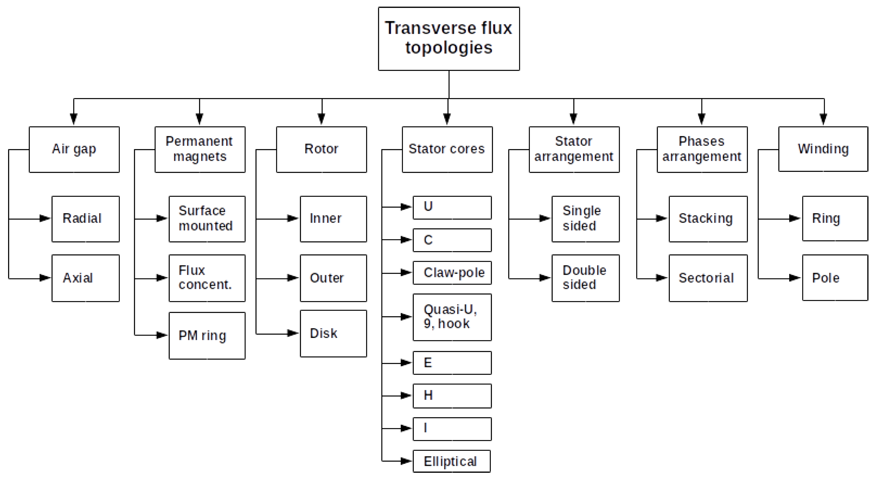
3. Transverse Flux Topologies

As in conventional radial flux machines, the main structural parts of TFMs are the air gap, rotor and stator. Besides, to produce torque (in a motor) or EMF (in a generator), both an excitation and an armature winding are needed. Most TFMs are excited by PMs that are placed on the rotor, whereas the armature winding is located in the stator, together with the magnetic cores (see Figure 2a). What essentially makes a TFM different from a conventional radial flux machine is the magnetic flux plane being perpendicular (“transverse”) to the rotation plane: this plane separation enables the magnetic and electric loads decoupling that is inherent to TFMs. There are many possible arrangements for the air gap, rotor, stator, PMs, winding(s) and phases, but in any case the choice of the TF topology is an essential stage of the design process, in order to meet the specs given by the machine application. In Figure 4, the main TF topologies are summarized, and they are further explained below.

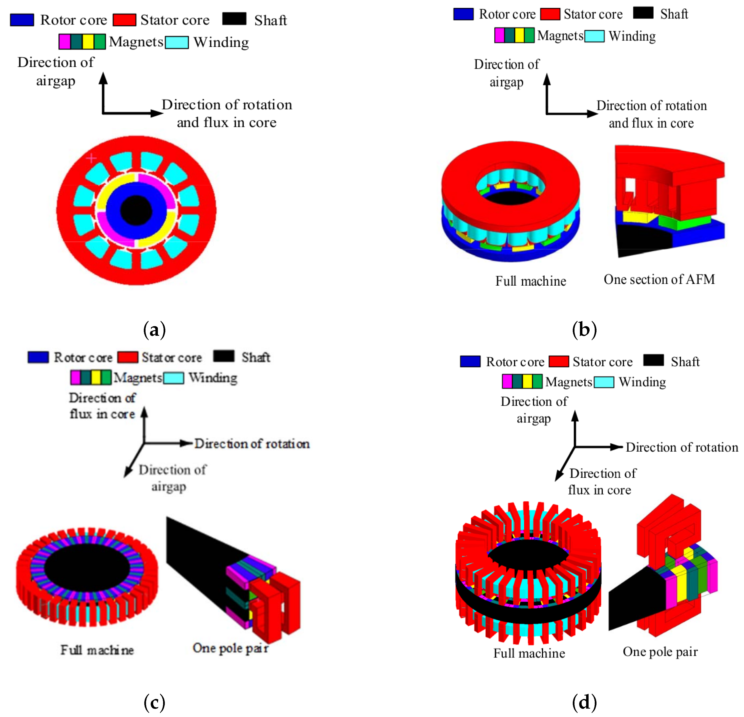
3.1. Air Gap (Radial, Axial)

The machine air gap is located between the rotor and stator, thus enabling the relative movement between the former and the latter. In TFMs, the air gap can have a radial or axial direction (Figure 1c,d), leading to multiple options in terms of magnets and stator cores arrangements. The air gap length is a key factor that modulates important magnitudes and phenomena that affect the machine performance, such as the air-gap flux density, leakage and fringing flux, magnetic saturation, etc. In the case of surface-mounted PMs, an effective air gap length (g) can be defined from the air gap and PMs length ( g a , g P M )—see (3)—since PMs magnetic permeability is close to that of air. This approach makes possible to treat both series-reluctances (air gap and PM) as one—see Figure 5—but it is not valid for flux-concentrating PMs, where the flux path is more complex.
g = g a + g P M
In TFMs, the air gap length ( g a ) is usually around 1 mm, whereas the PMs length ( g P M ) depends on the desired air gap flux density ( B g ), according to Figure 5 and (4) ( B P M is the remanent flux density of PMs). Leakage and fringing flux have been neglected in the analysis, as well as iron reluctances.
B g = B P M g P M g
The air gap length has an impact on cogging torque [101]. PMs length has a significant effect on the machine performance, but the number of poles is predominant [23]. Besides, if PMs are axially longer than the stator cores, the fringing flux in the axial direction produces torque [63,78,80].

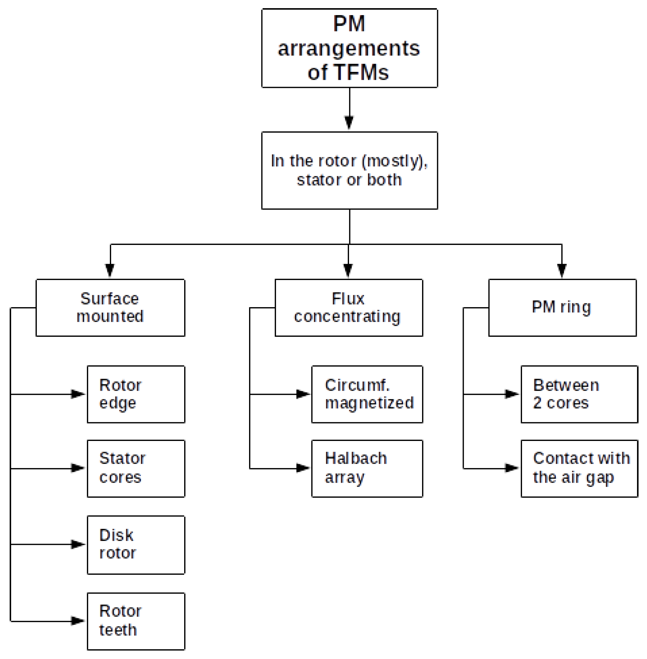
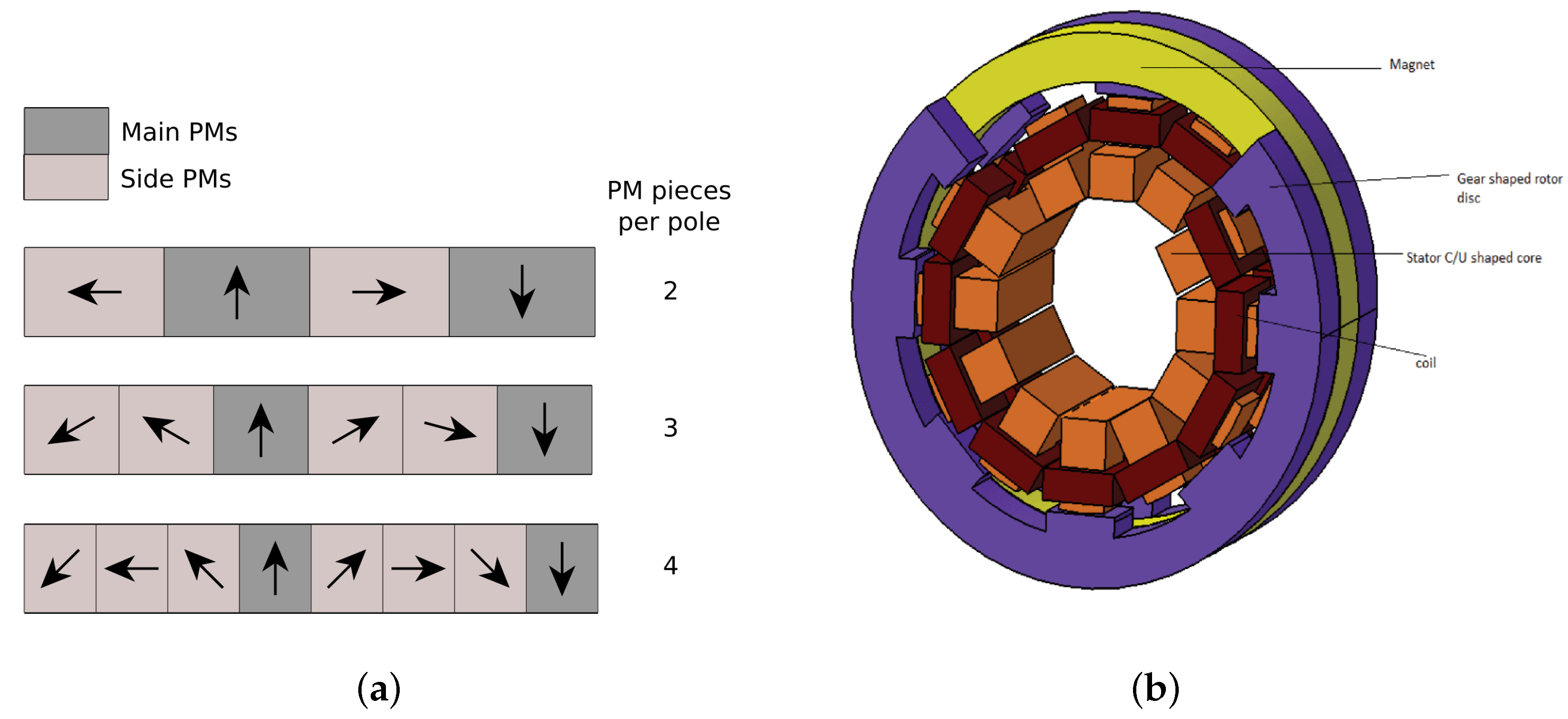
3.2. Permanent Magnets (Surface-Mounted, Flux-Concentrating, PM Ring)

Most of TFMs are excited by PMs, but it could be equally possible to have an electrically-excited TFM [21], a reluctance TFM with no magnets [102] and even a hybrid excitation (PMs and field winding) [50,53]. TFMs mostly have PMs on the rotor, but they can also be placed on the stator, or even both on the stator and rotor [103,104,105]. Possible PM arrangements of TFMs are summarized in Figure 6. There are two main options: surface-mounted PMs (Figure 7a) and flux-concentrating PMs (Figure 7b). In the case of surface-mounted PMs, the d- and q-reactances are similar, whereas in flux concentrating designs, the q-reactance is larger than the d-reactance [106].
Surface-mounted magnets are usually glued on the external or internal edge of the rotor—depending on whether the rotor is internal or external, respectively—but they can be also be glued to the stator cores [61,76,107,108,109], inserted in a disk-rotor [81,110,111] or embedded in the rotor teeth [112,113].
The flux-concentrating setup offers a higher air gap flux density—ferrite magnets can be used instead of rare-earth magnets to prevent saturation [91]—and guarantees that all PMs are active at all times, but the rotor construction gets more complicated [15]. Trapezoidal magnets have been explored as a torque-increasing and mass-saving option [97]. Through the definition of a flux concentration factor, it is shown that the air gap flux density, and so the torque density, increase with radial length of PMs and pole number [89]. However, the combination of high flux density and high pole number produces a strong reluctance torque and then cogging and ripple torque [96,97]. The most used flux-concentration techniques are the circumferentially-magnetized PMs in the rotor or the stator (Figure 7b) and the Halbach array (Figure 8a) [15,59,60,68,69,72,74,75,114,115]. The Halbach array is an arrangement of consecutive PMs that are magnetized in different directions: it favors a higher value of the air gap flux with a sinusoidal distribution, so a reduction of the back-EMF harmonics is possible without decreasing the average torque [64]. In any case, the number of PM pieces per pole (2, 3 or 4 usually) and the ratio of side to main PM width must be chosen carefully [75].
Other configurations use an axially magnetized PM ring between two iron cores (Figure 8b) [67,85,86,116,117] or are directly in contact with the air gap, thus eliminating the intermediate iron cores [118,119]. If that is the case, PM segmentation must be considered to prevent high eddy currents in a solid PM ring [85].

3.3. Rotor (Inner, Outer, Disk)

The TF rotor can be described in terms of its relative position to the stator (inner vs. outer, this is the case of radial-flux machines) and its shape (e.g., disc rotor for axial-gap TFMs).
An inner rotor leaves more free space in the stator for electric conductors, thus the power density can be increased [113]. It also favors the rotor attachment to the axis and so the housing design.
In outer rotor machines, the stator cores and the coils are placed in the inner region, thus increasing the active radial length and so the tangential force in the air gap [97]. Outer rotor machines also benefit from lower coil resistance (the current path is shorter due to the lower radius of the ring winding) and less rotor leakage flux (the adjacent stator pole areas facing the air gap are closer in an inner rotor TFM) [14,120]. When it comes to large direct-drive wind generators, outer rotor TFMs are easier to install and maintain [73]. This topology favors the introduction of the winding in the stator slots [82] and the magnetic shunts placement [121]. Inner and outer rotor TFMs with nearly the same volume and mass have been compared in [121]: the former has a power density of 0.90 kW/kg, whereas the latter reports 1.42 kW/kg, it is 1.57 times higher.
Disc-shaped rotor is a typical feature of axial-gap machines [15,17,59,60,61,63,66,68,69,72,76,81,87,91,110,114,115]. A claw-pole TFM with a discoid rotor produces more torque than other machine with a similar volume and cylindrical rotor [87]. Some advantages of the disc-rotor TFM presented in [110] are: lower inductance of the armature winding and power factor increase, higher rotational speeds, lower centrifugal force over PMs and more compact structure.

3.4. Stator Cores

The stator of TFMs is formed by magnetic cores shifted circumferentially. Magnetic cores guide the magnetic flux through the stator, and usually there is one magnetic core per stator pole pair. When talking about TFMs, there are no “slots” as in classical electric machines, because the stator is formed by magnetic cores and these are independent pieces. Many different magnetic cores have been investigated for TFMs applications (Figure 9):
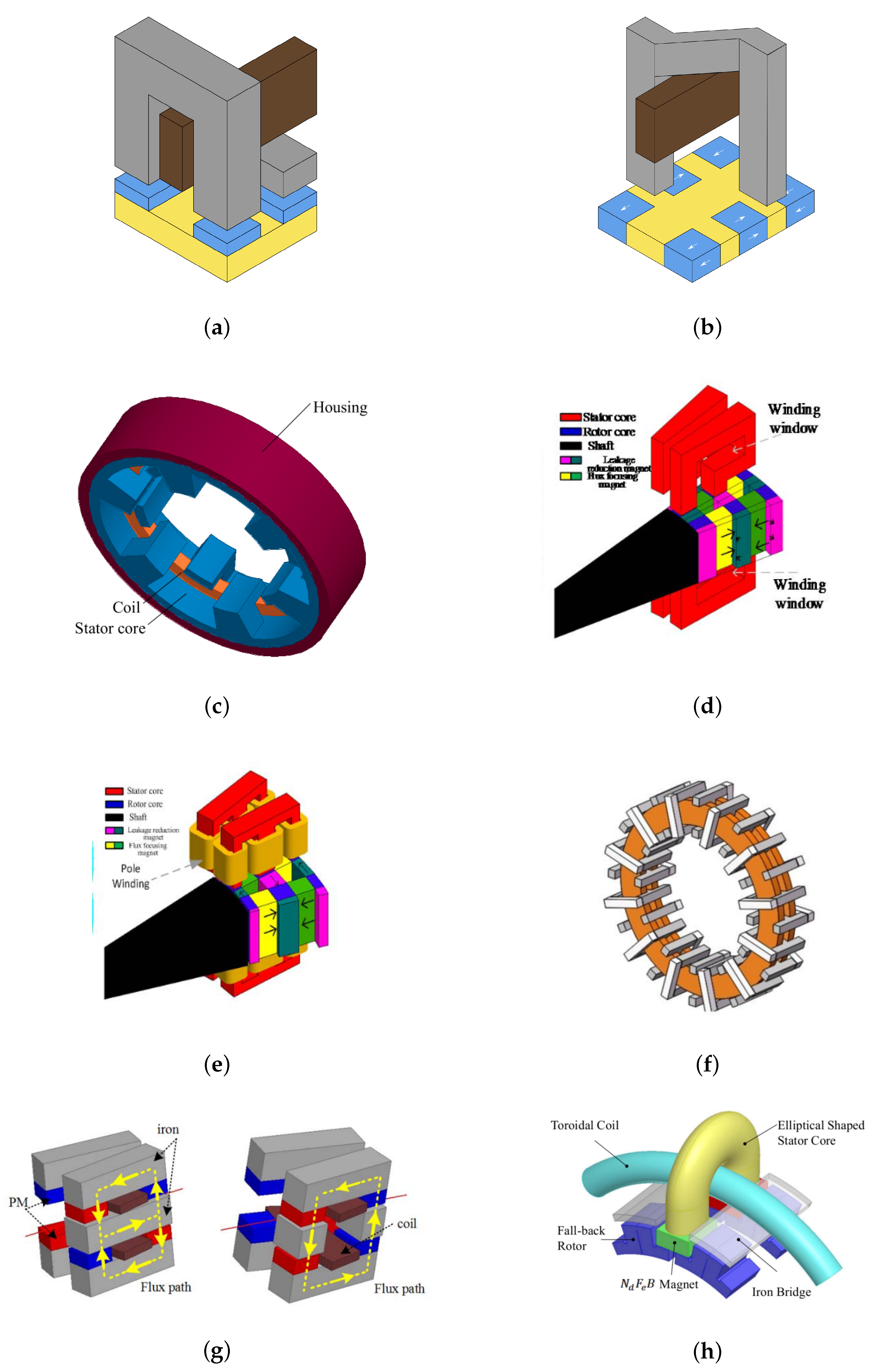
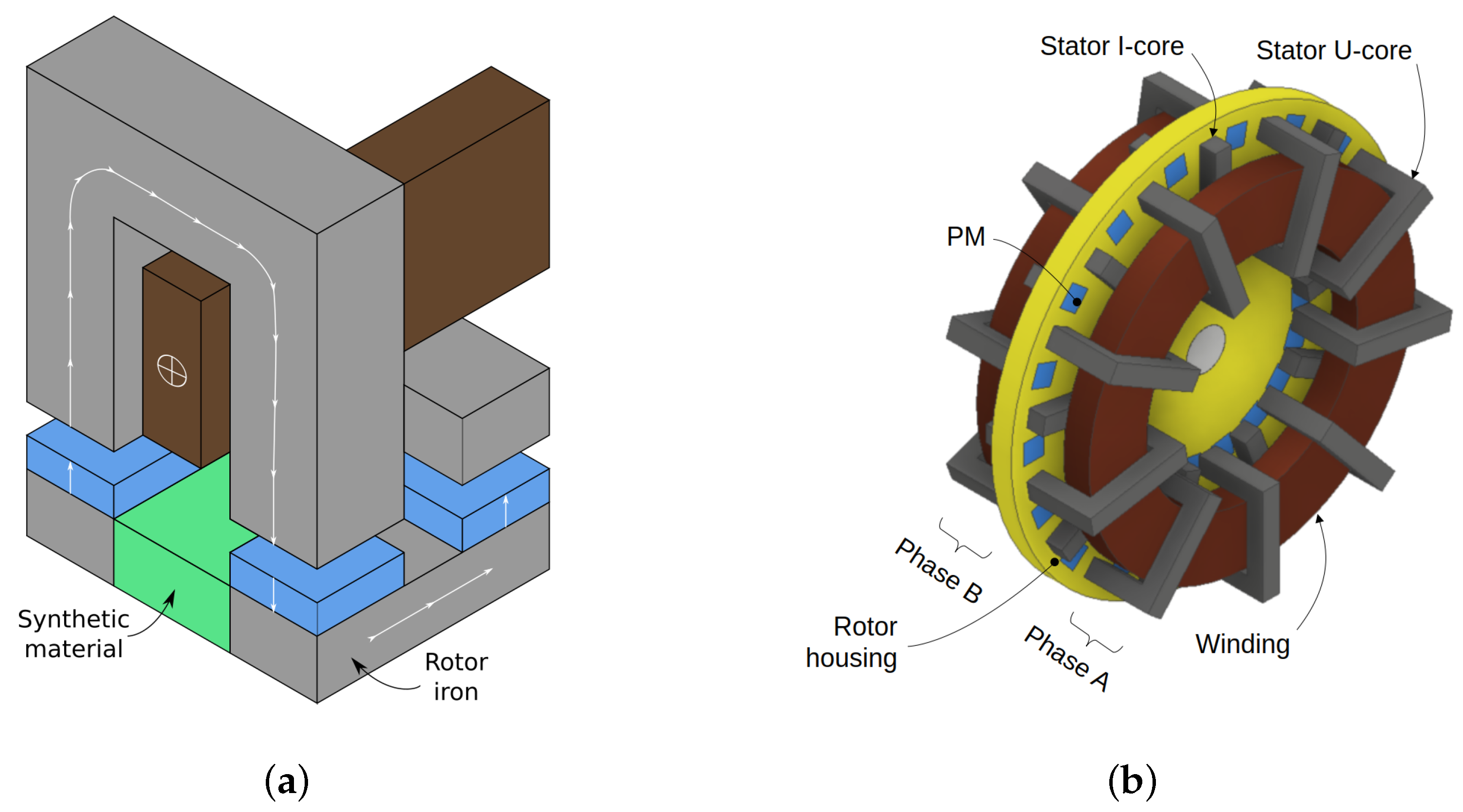
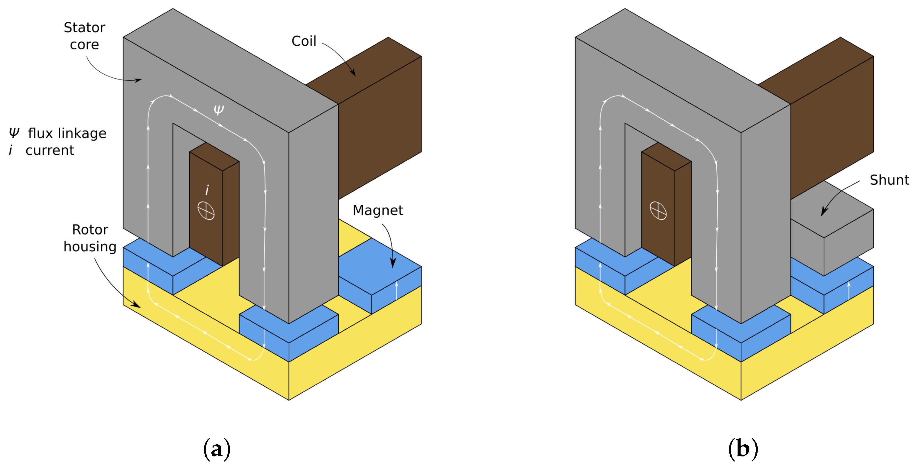
  • U-core. This is the basic magnetic core of TFMs, especially of those with surface-mounted PMs (Figure 9a). The circumferential shifting of the U-cores in the rotation plane forms the transverse flux plane of the magnetic flux. Variations of the classic U-cores have been introduced in [17] to explore four-coil arrangements.
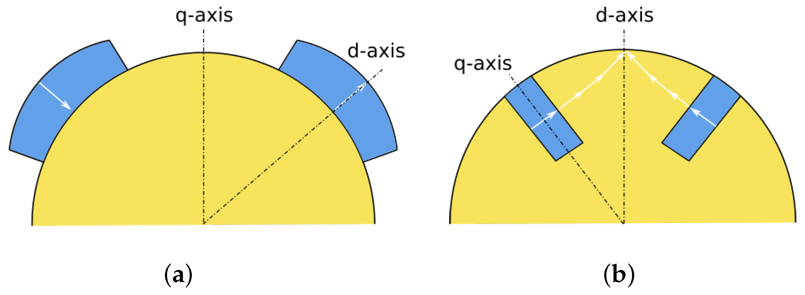
  • C-core [19,96,97]. In many publications the name “C-core” is equally used for C- and U-cores due to its similar shape, but in this review, the distinction made in [84] is applied: U-cores guide the magnetic flux in the axial plane of TFMs with surface-mounted PMs (Figure 9a), whereas C-cores guide the flux across a skewed line in TFMs with flux-concentrating PMs (Figure 9b). C-core TFMs benefit from lower losses and higher torque at the cost of a more challenging manufacture [84,97].
  • Claw-pole stator [8,16,25,87,95,98,122,123,124] or claw-pole stator and rotor [85,86]. Compared to a radial machine and a mutual flux path TFM with the same volume, the claw-pole TFM offers higher torque densities and its weight is lower. However, if the mass of the magnets is constrained instead of the outer volume, the torque capability of the claw-pole TFM is reduced significantly [25]. The manufacturing process of the claw-pole machine is problematic due to its dependence of SMC [16], but it is easier than other TFMs assembly [87]. Claw-pole machines take the advantage of flux concentration with single sided design, this is preferable to the complex design and manufacturing of conventional double-sided TFMs [99].
  • Quasi-U core [15,59,68,114], 9-shaped core [125] and hook-shaped core [67,72]. These three core shapes are very similar, and the same idea has been used in other publications [14,120]. The quasi-U core is basically a modification of the basic U-core to adapt it to an axial-gap, double-sided machine with Halbach array. The same happens with the hook-shaped machine, but it shows a better performance than quasi-U and E-core TFMs in terms of torque density, efficiency and power factor [72]. Ajamloo et al. propose a similar concept [67]. Additionally, 9-shaped cores with rotor teeth improve the single-sided stator space utilization and show greater torque density and lower torque ripple than a conventional TFM [125].
  • E-core [59,60,68,91,108,110,115,126]. The E-core boosts torque density and magnet utilization, shortening the flux path with the use of pole windings that are wound across each leg of the E-core [115]. E-cores have also been used with ring windings to obtain a double-sided stator [108,126]. The two “Us” that form the E-core can even have a different cross section to reduce the magnetic leakage between the poles of the inner rotor [126].
  • H-core [66]. The H-core in the stator facilitates the assembly process, resulting in a double-sided machine with two passive rotors [66].
  • I-core [61,76]. The usage of I-cores can be combined with L-shaped auxiliary cores [61] or simply used to configure a series or parallel flux path, depending on the way the magnetic field crosses the rotor [76].
  • Elliptical-shaped core [62]. The elliptical-shaped core benefits from lower mass and better flux utilization. The proposed design has higher back-EMF and lower cogging torque than a conventional TFM [62].
In Table 2, a comparison of TFMs found in the literature is shown, regarding the stator core and three basic performance indexes: torque density, efficiency and power factor. Another comparison can be found in [20], based on the machine ratings instead of the TFM topology.
One of the main drawbacks of the basic TF structure (Figure 2a), if not the main, is the existence of inactive magnets, that is, magnets which do not contribute to the flux linkage through the coil when other magnets lay under the U-cores. It is said that inactive magnets produce a “negative flux”, and this negative flux has a decisive influence on the low power factor of TFMs [23]. This phenomenon is further explained in Section 4.
A solution to minimize the negative flux of TFMs is the use of magnetic shunts, also named I-bridges (Figure 2b). If possible, magnetic shunts should have a triangular shape to avoid an excessive leakage flux between U- and I-shaped pieces [82]. The utilization of magnetic shunts can even double the output power of a TFM [121] and significantly increase the power density: for example, in [121] a TFM with an outer rotor and magnetic shunts shows a power density that is 1.62 times higher than the same machine with no shunts. Magnetic shunts are also related to cogging torque, in fact, it can be reduced by six times with the use of magnetic shunts [127]. Nonetheless, the maintenance of the machine becomes more complicated (the I-bridges must be disassembled to replace the winding) and the cost of the machine can also be affected, which is why shunts do not seem feasible for small motors [121].
Some other TF topologies do not need shunts because they inherently make use of all magnets at the same time, this is the case of TFMs with flux-concentrating PMs or with a double-sided stator.

3.5. Stator Arrangement (Single-Sided, Double-Sided)

The basic transverse flux structure is single-sided (Figure 2a), but the stator or the rotor can be duplicated in some way to make all the magnets active at all times. This option implies placing a second winding (series- or parallel-connected with the former) whose magnetic circuit is usually in phase with that of the previous one. If an angular shift of 180 electric degrees is adopted instead, and the windings are series-connected with opposite polarity, the even harmonics are canceled while the odd harmonics are doubled [67]. Besides, a double-sided TFM with parallel-connected stator windings can operate even if one of them is broken [59].
Most double-sided transverse-flux structures are based on the axial gap and disk rotor [15,17,59,60,63,68,69,72,76,81,91,114,115], skewed U-cores [14,120], hook-shaped cores [67], E-cores [108,126], H-cores [66] or a duplication of the stator on both sides of the rotor [127,128].

3.6. Phase Arrangement (Stacking, Sectorial)

In the stacking arrangement, the machine phases are axially placed like “blocks” along the rotor shaft. Ideally, there is no magnetic coupling between phases, so they are all independent of each other. The number of phases determines the harmonics content, which causes torque ripple: considering a maximum of 6 phases, it is shown that the ripple to average torque ratio of 2- and 4-phase TFMs is more than double the ratio of 3- and 6-phase motors [122]. It must be taken into account that even if only one phase is fed with current, the cogging torque on the rotor involves all phases [82]; however, the machine can continue operating with less specific torque and more torque ripple, leading to a fault-tolerant drive [114].
The sectorial arrangement consists of grouping together all the phases in the same rotor and stator stack, resulting in a less bulky design [113]. In this case, the electric and magnetic circuits are not decoupled, which results in lower power and torque densities [116].
A special phase arrangement for TFMs, named “planar aligned” has been explored in [124]: the motor components are integrated into the planets of an epicyclic gearing.

3.7. Winding (Ring, Pole)

Most of TFMs have a stator winding and the rotor excitation consists of surface-mounted or flux-concentrating PMs. Figure 10 shows the two possible winding arrangements of TFMs, that is, ring and pole winding. The ring winding is circumferentially wound through the slots of the stator cores, thus forming a single massive coil with long turns. This massive coil embraces the flux linkage of the whole machine or phase. The pole winding, however, comprises short coil turns that are wound around the legs of the magnetic cores, resulting in a multiplicity of small coils with short length. These coils can be either series- or parallel-connected [110], each of them embracing the flux linkage of a single pole.
A ring winding can be made with copper threads or even with copper sheets [97]. Ring windings have lower losses than conventional windings [120]. A square-shaped stator slot offers the best ratio of copper cross section to the length of the magnetic path [82], and it gives the minimum slot leakage [58]. The cross-section of the winding must be matched to the magnetomotive force of PMs in order to achieve the maximum output power of the machine [101]. However, there is part of the winding that does not contribute to the flux linkage, but causes copper losses and increases the active weight, for this reason it could be treated as an end winding although TFMs do not have an end winding [58], strictly speaking.

3.8. Some Special Transverse Flux Machines

  • In [89], a double rotor transverse flux machine is proposed as a compound-structure machine for hybrid electric vehicles. It has one flux-concentrating PM rotor, one passive TF rotor and a TF stator based on U-cores.
  • In [90], a hybrid flux machine is designed, it is named “hybrid” because the magnetic flux in the stator core is transverse, whereas the rotor flux is longitudinal. Its aim is to improve the magnets utilization and power factor, taking advantage of magnetic and electric circuits decoupling and low ohmic losses of TFMs and simple rotor construction, with single magnet layer per stack, and better magnet utilization of longitudinal flux machines. This hybrid flux machine delivers the same torque with 32% reduced magnet in comparison with other TFMs (conventional TFM with and without pole shaping), and also shows a better power factor and torque density with a slightly lower efficiency.
  • In [104], a dual-consequent-pole transverse flux machine is designed, which has PMs both on the stator and the rotor. Differently from common TFMs, the flux leakage of inactive magnets does not weaken the total flux, even it enhances it. Great torque per volume is obtained compared to literature.
  • In [8], a high-temperature superconducting (HTS) flux-switching transverse flux machine is designed using 3D-FEM and multiobjective optimization. It has two ring-shaped HTS-excitation coils in the stator, and also several concentrating armature windings that are wound around the U-cores.

4. Operation of the Transverse Flux Machine

In this section, the TFMs operation is explained. Most of the TFMs proposed in the literature operate as PMSMs. A switched reluctance generator with an integrated rotor that consists of main and PM auxiliary poles is investigated in [112]: this TFM is suggested for wind power generation due to their low cost and simple structure. A synchronous reluctance TFM is proposed in [102] with no PMs. Besides, in [5,6,7,8], several flux-switching TFMs are designed.

4.1. Pole Pairs and Size

As explained in Section 1, the number of pole pairs is a key aspect of TFMs design due to its influence on torque and EMF. TFMs also benefit from high number of poles in terms of cogging torque [128] and THD [110], but in small motors the manufacturing process gets more complicated [128]. A TF generator with 70 pole pairs for wind power has been proposed in [71].
TFMs have a small air gap and large diameter, and this can be advantageous in terms of mass and cost for wind power applications [73]. TFMs up to 5 m in diameter can be found in the literature [63], but most of them lay in the range of 0.1 to 0.25 m. The ratio of the stack length to the air gap diameter is a wide-used parameter in analytical design methods of TFMs [24,129,130]. In most of the TFMs found in the literature, the axial length is shorter than the outer diameter of the machine.

4.2. Torque, Speed and Efficiency Ratings

Torque and speed are the main parameters that characterize an electric machine performance: torque-speed-efficiency maps are a very descriptive tool [72,91,123] specially for motoring mode. TFMs show a low overload capability [25], so it must be taken into account when conducting simulations in a TF motor design.
Figure 11 depicts the torque-speed and power-speed ratings of some TFMs found in the literature [6,8,67,69,71,72,80,81,90,93,95,104,109,113,116,122,131], both for TF motors and generators. As shown in Figure 11a,b, most of the reported TFMs have their ratings up to 100 Nm and 2 kW: in Figure 11c,d, they are shown in detail.
The efficiency is a key aspect of modern electric drives, and it is closely linked to the machine losses: they are formed essentially by copper losses, iron losses, PMs losses, stray load losses and even housing losses (for example, if it is made of aluminum, eddy currents can be induced) [129]. As a rule of thumb, iron and PMs losses become significant when the fundamental frequency of the TFM is higher than 100 Hz [129]. In [85], a TFM and RFM losses are compared, showing that core and magnet losses are substantially higher for the TFM (whereas the output torque is similar), the total losses are comparable (resulting in a better efficiency for the TFM). Five methods have been reported for iron losses calculation of TFMs: Steinmetz, Jordan and Bertotti equations, the Modified Steimetz Equation and the Generalized Steinmetz Equation [123]. Friction torque, and their associated losses, are usually neglected, but they can be easily estimated with a extrapolation of the no-load torque over speed (n) curve to n = 0 , assuming that friction torque is constant over speed [95,123].

4.3. Torque Ripple Minimization

Usually the analysis of the torque of an electric machine is based only on the electromagnetic torque, that is, the “total” torque. This torque waveform is restricted to a specific machine topology and size, and it hides several contributions to the electromagnetic torque. Therefore, a preliminary but straightforward study of the torque must be conducted.
Electromagnetic torque (T) of TFMs is based on three components, according to (5): synchronous torque ( T s ), reluctance torque ( T r ) and cogging torque ( T c ).
T = T s + T r + T c = i s i r L m θ + 1 2 i s 2 L s s θ + 1 2 i r 2 L r r θ
i s , i r are the stator and rotor current; L m is the mutual inductance; L s s , L r r are the self-inductances of the stator and rotor; and θ is the electric angle (rotor position).
In any electrical machine, the stator self-inductance ( L s s ) keeps constant if there are no saliencies, inset PMs or flux-concentrating PMs on the rotor, this is the case of many TFMs. Due to the modular structure of the stator of TFMs, formed by several U-shaped pieces shifted circumferentially with an air space between them, the rotor self-inductance ( L r r ) varies with the electric angle. Assuming a sinusoidal variation, and taking into account only the first harmonic, the rotor self-inductance fulfills (6), where the d and q subscripts refer to dq axes. The mutual inductance ( L m = L s r = L r s ) follows (7).
L r r ( θ ) = L r r , d + L r r , q 2 + L r r , d L r r , q 2 cos ( 2 θ )
L m ( θ ) = L m , m a x cos θ
According to (8), the stator current can also be assumed as sinusoidal. The rotor current is constant in any synchronous machine with PMs (PMSM), in this case i r denotes the equivalent current of PMs. The initial position of the rotor has been set to δ 0 = 40 °.
i s = I s cos ( ω t ) i r = I r θ = ω t + δ 0
The machine inductances, currents and torque, assuming a sinusoidal variation, are depicted in Figure 12, this corresponds to a 3-phase, 2 kW synchronous motor operation whose rated values are shown in Table 3. Sinusoidal inductances can be replaced by trapezoidal waveforms (Figure 13), this is a more realistic approach for PMSMs such as TFMs. Several conclusions can be drawn from this preliminary analysis:
  • Even in the sinusoidal case, single-phase torque has a significant torque ripple, whereas 3-phase torque is constant due to the cancellation of three sine waves shifted 120°. The main contribution to the single-phase torque ripple is the synchronous torque.
  • The fundamental frequency of the single-phase torque is twice that of the main machine frequency ( ω ).
  • The average synchronous torque increases with L m , m a x , I s and I r . For the case study, only I r increase the single-phase torque ripple.
  • The reluctance torque is zero because it has been assumed that L s s is constant. This is the case of TFMs with surface-mounted PMs.
  • The average value of the cogging torque is zero. The amplitude of the cogging torque increases with rotor current ( I r ) and the difference between L r r , d and L r r , q .
  • Trapezoidal inductances, a typical waveform of PMSMs, introduce new harmonics in the single-phase torque and distort the 3-phase torque. The single-phase torque ripple increases significantly.
An alternative method to calculate the torque analytically has been proposed in [94]: the reluctance torque is calculated with (5), interaction torque is calculated using an equivalent current for PMs and cogging torque is calculated through magnetic energy.
Torque ripple ( κ ) is usually calculated using (9) [100].
κ ( % ) = 100 T m a x T m i n T a v g
where T m a x , T m i n and T a v g are the maximum, minimum and average torque.
In many TFM studies, the torque ripple analysis is basically focused on the cogging torque, but the synchronous torque and reluctance torques are equally relevant contributions to torque ripple [92]. However, cogging torque is the only component that is present with no stator current (and it has zero average value, as shown in Figure 14 [93]), so it has a specific influence in the machine start up (e.g., wind turbine applications) [67]. Most of cogging reduction techniques result in lower average torque [122], this is why cogging minimization is a key aspect of TFMs design.
Two main categories of torque ripple reduction techniques can be established: those in which the machine structure is changed and those that are based on control strategies. Changing the machine structure (PMs, stator or rotor) usually requires various 3D-FEM calculations, thus increasing significantly the calculation time. The resulting topology is often more complex, so the manufacturing process gets more difficult and the machine cost is higher [92].

4.3.1. Changing the Machine Structure

As said before, several changes can be introduced in the TFM structure to reduce cogging torque, and this alterations can affect PMs, stator or rotor. The effectiveness of the reported techniques is difficult to compare because they are constrained to different machine topologies, so results of Table 4 must be interpreted carefully.
The use of Halbach magnets seems to be a promising cogging reduction technique because it does not lessen the average torque [75]. In the design process, it is essential to optimize the PMs arc ratio for the arrays: using the same PM pieces size would not be always the good option to reduce the cogging torque [64]. The axial PMs segmentation, also named PMs skewing, is another well-known technique for TFMs [16,77] that imitates the slot skewing of classic electric machines.
Similar to PMs, the skewing can also be applied to the stator [19,99]—even with more than one step [19]. Tooth pitching [98] imitates the coil pitching of radial flux machines. Pole shaping can also be applied both to the stator [114] and rotor [112,117], as well as pole width adjusting [98]. Magnetic shunts can make up for a short distance between the adjacent magnet to reduce cogging torque [127]. Stator and rotor notches have also been tested in a TFM [118]. The number of phases also has an influence on cogging torque both in a stacking [122] and sectorial [117] arrangement of phases. A combination of different cogging reduction techniques is possible, for example, in [69] different methods have been analyzed together: rotor and stator pole numbers, air gap diameter, pole width, skewing and stator displacement. In [117] the rotor pole shaping, increase in number of repetitions and increase in number of phases have been tested.

4.3.2. By Control Strategies

Cogging torque compensation by control strategies benefits from a better adaptation to different TF topologies, because the machine structure is not modified in any way. A current compensation control has been reported in [92], based on seven nonlinear dynamic models involving the relationship among main motor parameters, and these parameters are fitted in real time and the torque is calculated by 3D-FEM. The torque ripple is reduced and the average torque is even improved. In [81], two PI controllers are used for d- and q-current in order to reduce the torque ripple. Instead of a 3-D FEM computation, the Schwarz–Christoffel conformal mapping can be used: the computation time is just 29 min versus 7 h of FEM [19].

4.4. Leakage and Power Factor

Power factor (PF) of electrical machines is closely but not exclusively related to leakage flux. Strictly speaking, the “leakage flux” is the flux that does not cross the air gap; the flux that crosses the air gap but weakens the main flux in some way—inactive PMs, for example—should be named “negative flux” (see Figure 15 [23]. This negative flux can be around 50% of the main flux, but the use of magnetic shunts can reduce this proportion to 2–3% [127]. Negative flux is the main cause of the low power factor of TFMs [23,79]. Low PF also means that the machine is highly tolerant to a terminal short-circuit [83] due to its high synchronous reactance [98].
TFMs control is based on classical techniques for PMSMs control [18]. Figure 16 shows the (a) equivalent circuit and (b) phasor diagram of the iq control of a synchronous machine, under the assumption that both the stator and the rotor are cylindrical, so the d- and q-inductances are equal. If the resistive voltage drop is negligible compared to the inductive voltage drop, the power factor can be calculated using (10) [23]:
cos φ = E ( I q X ) 2 + E 2
In order to take into account the contribution of the “negative flux”, a flux factor can be defined to measure how much of the total flux is actually producing torque. This factor depends only on the air gap geometry [80]. It can be shown that the back-EMF (E) is proportional to the flux factor, PMs flux and speed; the current in the q-axis ( I q ), is proportional to the torque and inversely proportional to the flux factor and the number of stator cores; and the synchronous reactance (X) is the sum of the main path reactance and the leakage reactance. Therefore, the PF and torque of a TFM are closely related through the flux factor [23], so the utilization of PMs at all times becomes a key aspect of TFMs design.
Under iq control (the first of the two operation modes within field oriented control), leakage flux becomes significant in the q-axis rotor position, because the leakage and main flux paths are then comparable [120] and current reaches its maximum. This causes a large flux circulating through the stator instead of the rotor, affecting magnetic saturation (and therefore adding back-EMF harmonics) and increasing inner voltage drop (and then the voltage requirements of the inverter) [112]. PMs also affect the power factor: NdFeB magnets suffer from low power factor (from 0.35 to 0.55) and magnetic saturation because of high leakage inductance and excessive armature reaction, and ferrites are prone to low PFs due to the low magnetic loading [6]. Four components of the TFM inductance have been categorized: air gap inductance, slot leakage inductance, end winding inductance, and fringing inductance [7]. When it comes to the stacking arrangement of phases, phase-to-phase coupling may occur. This can be partially solved by increasing the axial gap between phases, but even so, the self-inductances may be unbalanced if the axial separation is too low [120]. Nonetheless, phase-to-phase coupling is generally neglected in FEM simulations in order to save computation time (only one pole pair of one phase is modeled).
Torque density and PF are inversely linked [65], therefore a trade-off between both magnitudes must be found. Some ideas to increase PF can be found in the literature: increasing the distance between poles to avoid flux leakage [128], the use of magnetic shunts [127], a phase-to-phase axial separation [120], modifying the core shape (some kind of skewing, at the cost of lower no-load flux) [14], and reducing the number of stator C-cores (lower torque is achieved) [23,79].

4.5. Materials and Manufacturing

A variety of materials converge in electric machinery. Magnetic cores of TFMs are essentially made of the so-called iron laminations—actually it is electric steel—or soft magnetic composites (SMC). Neodimium-iron-boron (NdFeB) and ferrite magnets are utilized depending on the PMs arrangement (surface-mounted or flux-concentrating). Some other parts of the electric machine can be made of solid iron, such as magnetic shunts—high eddy currents can be induced [127]—or rotor core [121]. Aluminum and plastic are commonly used for the stator and rotor housing.
In any case, the cost of materials determines the economic viability of an electric machine design. In Table 5, the cost of the main materials used in TFMs is shown, regarding that the total cost of the machine will depend on the mass. Materials properties are further explained below.

4.5.1. Magnetic Cores (Laminated Steel, SMC)

Among the electrical steel, a widespread used variant in TFMs literature is the M270-35A steel: according to the standard designation, “M” means that it is electrical steel, “270” means that the losses at some specified conditions (typically 1.5 T and 50 Hz) are 2.70 W/kg, “35” means that the nominal thickness is 0.35 mm and “A” means “non-oriented grain”. Different lamination directions can be combined to match the flux path, as shown in [107]. Iron wires have been explored in [132] as an alternative for laminations in TFMs: theoretical losses of an iron wire are 3/8 of a sheet losses, but a heat treatment of the iron is necessary in order to obtain reasonable results. For example, in [99] the magnetic annealing of a cobalt-steel alloy increases the saturation flux density, and hence the peak torque.
Another well-know material for TFMs cores is SMC. SMC is formed by electrically insulated iron powder particles (typically in the range of 50 µm to 150 µm [131]) that are compressed at pressures between 600 and 800 MPa, and then a heat treatment is usually applied to relieve the mechanical stress [98]. A robust optimization method for 6-sigma quality manufacturing of a TFM with SMC has been proposed in [131].
Table 6 shows the basic pros and cons of SMC versus iron laminations. For high-pole machines with 3D flux paths, such as TFMs, SMC offers lower losses at high frequencies and magnetic isotropy, whereas its magnetic permeability is significantly lower. A comparison between two TFMs with stator cores made of laminations and SMC is made in [97]: the machine with laminated cores shows a slightly lower mass and higher back-EMF, but SMC provides lower cogging to average torque ratio, higher load torque and higher torque density.

4.5.2. Permanent Magnets (NdFeB, Ferrite)

NdFeB magnets are widely used in electric machinery due to their high energy density and remnant induction (higher than 1 T). N35 to N45 PMs have been used for TFMs in the literature: “N” denotes a neodymium magnet and the number is the energy density in megagauss-oesterds. Samarium-cobalt (SmCo) magnets have been also used, but in less proportion. Ferrites are other alternative that is associated to flux-concentrating arrangements due to its lower remnant induction. According to literature, in the field of TFMs (with very few exceptions) surface-mounted PMs are rare-earth magnets (such as NdFeB or SmCo) and flux-concentrating PMs are ferrite magnets.
PMs demagnetization can occur if the armature reaction or temperature are too high. In [6,75], PM demagnetization studies are conducted on TFMs: the magnetic flux density map is obtained through 3D-FEM, and the areas with low magnetic flux density are compared with the PM demagnetization curve. In [86], analytical equations for PMs magnetic properties are proposed and then an electromagnetic-thermal FEM model is computed. Halbach arrays of PM have a risk of demagnetization due to the perpendicular directions of the PMs flux [75], as well as ferrite magnets due to their low coercivity [6]. Three TFMs with ferrite, NdFeB and SmCo magnets have been compared in [15]: NdFeB and SmCo magnets offer much higher torque, torque density and power factor at the cost of higher PMs weight and PMs price.

4.5.3. Rotor and Stator Housings

The rotor and stator housings are not part of the electromagnetic circuit of an electric machine, but their design significantly affects the mechanical and thermal behavior of the machine, as well as its cost.
Aluminum and synthetic materials have been used (at least for prototyping) in TFMs literature. In [127], the stator housing is made of aluminum, leaving enough distance between PMs and aluminum to avoid eddy currents, whereas in [97], the rotor housing is made of aluminum instead. As shown in Figure 17a, sometimes iron can be replaced by synthetic materials to reduce the machine weight [82]. Figure 17b shows a TFM design where the whole rotor housing is made of plastic (PLA) [93]. In [81], the stator is also made of PLA (3D-printed), and it is said that due to mechanical and thermal constrains the current density is limited to 3 A / mm 2 . In [110], the rotor disk is made of paper sheet with phenolic resin, whereas the stator is made of compact plastic. In flux-concentrating designs the pole pieces must be clamped during the epoxy curing because the resulting field tends to eject the pole pieces [97], and some smalls gaps and thin oxidation layers in the SMC cores can be found.

4.6. Power Converters and Control

Power converters and control strategies of TFMs are similar to those of PMSMs: in [18] a review is made, focusing on wind power applications. Power converters reported in this reference are: diode bridge converters, back to back converters, matrix converters and cyclo converters, but the information given is not specifically related to TFMs. Control strategies reported in the same reference are field-oriented control (FOC) and direct torque control (DTC), these are classical techniques for PMSMs control.

4.6.1. Power Converters

The power factor of TFMs is usually low, thus increasing the power converter rating. In direct-drive systems, the machine cost is higher than the PWM converter cost, so the ratings increase caused by low PF can be acceptable [63].
A three-pulse inverter is used in [102]. Space vector PWM modulation is applied in [120]. For tidal applications, in [80] a fully rated power converter with an active front end connected back-to-back to the grid-tied inverter is proposed. Interleaved PWM control of a SiC-based drive is proposed in [133] to coordinate the phases of the two stator sets of a double-sided TFM: it offers a significant reduction in the capacitance, current and current ripple requirements of the DC-link capacitor bank, and smaller EMI filters are needed.

4.6.2. Control Strategies

According to TFMs literature, three basic ways to implement FOC have been explored for TFMs control: iq control, maximum torque per ampere (MTPA) control and maximum efficiency (ME) control. The iq control imposes that the d-axis current is null ( i d = 0 ), so the current phasor is aligned with the q-axis. This constraint cancels the reluctance torque, so the machine torque capability is not fully utilized: that is why MTPA control emerges as an alternative to iq control. To introduce the machine losses in the control scheme, ME control strategy can be used. A specificity of TFMs for FOC is their high inductance and armature reaction, this makes that in the field-weakening region the base speed is only marginally increased [6]. PI controllers are easy to design and implement: in [112], a PI control strategy is used for a TF generator output voltage, whereas in [15,68,115], a PI speed controller (and estimator) and hysteresis current controller are used to control a TF motor.
An iq control has been introduced in analytical sizing equations for TFMs design [23,79,80,93,104,129]. In [81], an iq control scheme with 2 PI controllers (one for each dq voltage) is proposed.
The MTPA control strategy is defined by (11) [123], where T is the machine torque (having substracted the torque associated to iron losses), d and q refer to the dq axis and P C u denotes copper losses.
max T i d 2 + i q 2 or max T P C u
In the case of a conventional three-phase PMSM, the relation between i d and i q can be derived for MTPA (12) [95].
i q ( i d ) = ψ P M L d L q i d + i d 2
However, the ME control strategy takes into account the total losses ( P l o s s ) instead of the copper losses, as shown in (13) [123].
max T P l o s s
MTPA has been explored for TFM applications [14,85,120]. A SISO current control, based on MTPS, is proposed in [95] together with a 8 kHz PWM inverter. In [123], MTPA and ME are compared: ME shows slight improvements.
An auto-piloted TFM has been presented in [102], the proposed machine has no PMs and operates as a synchronous reluctance machine. Model-free predictive current control is presented in [118]. Dynamic compensation control (of current) with adaptive parameter correction (of the strand inductance) for a TF generator is proposed in [71], a recursive least square algorithm is used for this purpose. A similar approach (“current compensation method and variable parameter PID algorithm based on real-time inductance”) has been presented in [92] for a 5-phase TF motor to reduce the torque ripple. A predictive current control strategy is adopted in [133].

5. Design and Modeling Techniques

Analytical methods (sizing equations and magnetic equivalent circuits, MEC) and the finite element method (FEM) are the two main TFM design and modeling techniques. The former shows a reduced computation time but low precision, whereas the latter offers higher precision at the cost of a significant computational burden. In the classical analysis of electric machines, these methods have been applied to the electromagnetic modeling of the rotor, stator and air gap, but in recent years, other applications have emerged, such as optimization algorithms and the mechanical and thermal modeling of the whole machine.

5.1. Analytical Methods

Sizing equations are one of the most used techniques in electric machinery design, specially for preliminary analysis. Starting from the machine specs (“outer” parameters, such as torque or speed), the “inner” parameters, (such as the air gap flux density or inductance) are obtained.
Some remarkable sizing equations have been used in TFMs literature. General sizing equations for converter-fed machines were proposed by Huang et al. [130]: the aim was to compare electric machine topologies with different EMF and current waveforms. This model has been applied to TFMs by the same authors [24] and others have reproduced it in other TFM designs [72,84,91]. Using these general-purpose sizing equations, it can be shown that a TFM with rare-earth magnets can have a volumetric power density that is nearly twice that of a squirrel cage induction machine [24]. Other torque and EMF equations have been proposed in [65]. Another method consists of replacing PMs with their equivalent currents, introducing a flux factor to account for the flux that does not produce torque. This approach uses a complex permeance method to calculate the magnetic flux and the flux factor is calculated through the Schwarz–Christoffel conformal mapping [78]. After that, back-EMF can be estimated by conservation of energy [78] or more precisely calculated using a virtual mutual inductance approach [79]. The proportional-logarithmic transformation maps the cylindrical domain into a rectangular one. The analysis is valid for different TFMs and both square-wave and sinusoidal stator current; however, iron reluctance and cogging are neglected [78]. Some design curves for TFMs have been proposed, based on the previous model [80]. Analytical expressions of the electromagnetic torque of synchronous machines, in terms of internal voltage and phase current waveforms and the number of phases, have been presented in [122], then a study on the odd harmonics of internal voltage and phase current that affect torque ripple and average torque is made. Electromagnetic torque can also be calculated through the Maxwell stress tensor, as in [134]. Analytical equations for core and PM losses are proposed in [85]. A full design approach (sizing equations, nonlinear MEC, optimization and FEM) is proposed in [63], taking into account the dq axis rotation and magnetic saturation. A similar method is used in [67]. A flexible methodology for the analytical design of TF generators is presented in [26], but the the verification is made using 2D-FEM. In [93], the magnetic cores and stator and rotor housings are designed by a combination of the dq model and MEC.
Magnetic equivalent circuits (MEC) are another analytical method for TFMs design and modeling. Their equations are analogous to the Ohm’s law and Kirchhoff laws, but with magnitudes such as magnetomotive force, magnetic flux and reluctance. In this approach, the flux path is defined through flux tubes that are tabulated for different geometries: their analytical expressions can be found in electric machines literature, for example, in [135]. Magnetic saturation (B-H curve) can be taken into account in MEC solving: for example, in [60], the Gauss–Seidel method to solve the nonlinear equations and in [109] the Broyden method is used. Different MEC approaches for TFMs can be found in TFMs literature [60,70,89,94,109,119,136].
The magnetic charge method has been also applied in very few publications, such as [137]: at the moment, it is much less used for TFMs design than sizing equations and MEC. In this case, the magnetic field is calculated through the reduced scalar potential.

5.2. Finite Element Method

In the finite element method (FEM), Maxwell equations are solved together with the material laws. Figure 18 shows a color map obtained from a FEM simulation of an axial-gap TFM using Flux3D [93]. FEM shows higher precision than MEC at the cost of higher computation time, specially for optimization problems: for example, in [67], FEM is 20 times slower than MEC, and in [63] the optimization of the nonlinear MEC takes 57 min, whereas FEM-based optimization takes 40-50 h. Mesh generation affects significantly the computational cost, that is why extruded meshes should be considered for TFMs if possible: in [82] a 2D-extruded mesh is used (with a linear approximation of the machine geometry) and in [102] a partially extruded 2D-mesh is applied.
In the field of TFMs, the most common approach are 3D simulations, but also surrogate 2D models have been used instead [26,31,63,78,138]. Among the previous references, only in [78,138] have 2D- and 3D-FEM results been compared, showing a good agreement. Authors in [31] propose a multi-fidelity model that combines both 2D and 3D-FEM simulations in order to obtain reasonable accuracy and computation time.
Analytical and FEM results have been compared for a hybrid TFM in [90]: the relative error is lower than 5% for the flux linkage and back-EMF, whereas the error is 12.8% for torque.

5.3. Optimization

Optimization deals with maximization and minimization of objective functions, starting from a set of values for several decision variables. The most simple optimization method is the parametric study, where the objective function is computed for a fixed set of variables and the results are plotted. Nevertheless, optimization algorithms make a systematic choice of the values for which the objective function is computed. Both parametric studies and optimization algorithms can be equally applied to the sizing equations, MEC and FEM.
Parametric studies have been widely performed in TFMs literature. In [15], the number of poles, air gap length, flux focusing factor, two design ratios and pole embrance are varied: the latter has a significant impact on the EMF shape. The influence of many geometric parameters of a claw-pole TFM with skewed PMs is analyzed in [16]. In [64,75], the PM arc ratio and the number of PM pieces per pole are varied in a TFM with Halbach arrays of PMs. Four levels are considered in [67] for PM length, stator tooth width, and coil turn per phase, and after performing the experiments, the results are submitted to analysis of mean and analysis of variance (ANOVA): it is shown that the stator tooth width has a great impact on the ratio of average torque to torque ripple. In [90], different magnitudes (flux linkage, back-EMF, torque, etc.) are studied as a function of poles and pole arc-to-pole pitch ratio. The dependence of the average torque with pole number and dimensions is analyzed in [72,91]. In [101], a parametric analysis is conducted, comparing two inner and outer rotor TFMs with different air gap lenght and coil cross section: the aim is to study their impact on the cogging torque and the output power.
Different algorithms have been applied for TFMs optimization, such as genetic algorithm [31,88,93,98,100,102,112] (NSGA-II in [88,93,100]), particle swarm optimization [15,100] (MOPSO in [100]), imperialist competitive algorithm [70] and Hooke–Jeeves algorithm [63]. Before the experimentation, to reduce the number of decision variables the Taguchi method can be applied [100], it consists of four stages [69]: identification of the design variables, develop the experimental matrix and conduct experiments, analysis, analysis of means. Taguchi method has been applied in some publications about TFMs [67,69,75,77,100]. For the function approximation, the Kriging method has been used [31,100,112], sometimes with variations [31]. Other Gaussian Process Regression (GPR) algorithm has been applied in [88], GPR is a kind of machine learning method based on Bayesian statistics. Other approximation methods applied to TFMs are the response surface technique and RBF neural networks [100]. Some objective functions that have been used in TFMs literature are: cogging minimization [112], multiplication of the no-load airgap flux, coupling coefficient and coil area [14,120], maximization of the ratio of average torque to torque ripple [67], minimization of the cost (initial cost of the machine and PWM converter, cost of losses over time and penalty for overheating and PM demagnetization) [63], minimize a weighted function that takes into account the torque ripple and the ratio of the average torque to the base design average torque [102], breaking torque, generated power and torque ripple [100].

5.4. Prototyping

Prototyping is usually the last verification stage of TFMs design, where some measurements are made on a real TFM in order to validate analytical and FEM models. Three-dimensional printing [81] and the use of synthetic materials [81,82,93,110] have been reported as accurate techniques to obtain cheap TFM prototypes. Figure 19 shows two examples of TFM prototypes from the literature. Experimental setups of TFMs literature are mostly based on FOC: Figure 20 shows a basic FOC control scheme, and Table 7 presents more information about the involved components. Usually, a load motor is connected to the TFM shaft, and it can be either an asynchronous motor [14,95,110] or a PMSM [59]. Both the load motor and the TFM are driven by an inverter. On the mechanical side, torque sensors and encoders are used to obtain feedback data for the FOC. In [102], three transoptors and light-reflecting disks are used to control an auto-piloted synchronous reluctance TFM.

5.5. Mechanical and Thermal Modeling

In recent years, mechanical and thermal FEM simulations allow us to complete the classical electromagnetic analysis. Noise and vibration of PM machines can be caused by aerodynamic, mechanic and electromagnetic sources: in medium power rated machines, the electromagnetic sources (cogging torque, torque ripple and magnetic radial forces) are predominant. Lower torque ripple does not guarantee less vibration or noise: the stator vibration is caused by the normal component of the electromagnetic force, and this stator vibration is the main source of acoustic noise in PM machines [59].
In [68], a complete mechanical analysis of a TF generator is made, using 3D-FEM and prototypes. First, rotor stresses (magnets yield and tensile strengh and eposy shear stress) at rated speed are checked through FEM, then a rotor fatigue analysis is made based on a speed cycle. Vibration is basically related to torque ripple, because “electromagnetic source is predominant in low to medium power rated machines”. Finally, a structural analysis is made mapping the axial force and using FEM, and axial acceleration, noise and cogging torque are experimentally measured. In [111], an analysis of the eccentricity is made, this includes static eccentricity, dynamic eccentricity, inclined rotor and run-out faults. Eccentricity faults are caused by inner machine defects, whereas torque oscillations are usually generated out of the machine. In [91], another structural analysis is made, and it is pointed out that PMs behavior must be checked at high speeds due to their low tensile yield strength.
Conduction in the solids and convection of the surfaces in touch with the air are the two main heat transfer mechanisms in electric machines [74]. Thermal analysis of TFMs can be conduced through steady-state thermal networks [58], transient thermal networks [74] or FEM simulations [82]. Two methods for losses calculation using FEM have been reported: simultaneously with the electromagnetic analysis (very time-consuming) and as postprocessing [74]. In [74], a compete analysis of thermal losses is made, and it is shown than in this case study, iron and copper losses (Joule and hysteresis) are much higher than PMs losses. Furthermore, the TFM proposed in [86] shows higher core losses and much lower copper losses than a RFM.
Cooling is a key aspect of electric machinery, but it has not been studied in-depth for TFMs. Some water- or liquid-cooled TFMs have been found in the literature [25,58,82,83,86] and a high-temperature superconducting TFM is proposed in [8] with a Dewar cooler. In [86], it is said that TFMs benefit from an efficient cooling due to their lack of end-windings, lower PM temperatures and no hot spots in the ring coils. According to [116], cooling is more tedious for outer rotor TFMs. For aircraft applications, liquid cooling is not suitable due to safety, mass, and maintenance restrictions [97].

6. Conclusions

In this paper, a comprehensive review of TFMs topologies and design is made, dealing with TFM applications, topologies, operation, design and modeling. TFMs show high torque and power density, and these are unique merits for direct-drive systems such as wind turbines and in-wheel traction. The basic TFM structure consists of a ring-shaped coil that is embraced by stator U-cores that guide the magnetic flux from one rotor permanent magnet (PM) to another. Due to the “transverse” magnetic plane, it is possible to increase the number of pole pairs keeping the machine diameter constant. Moreover, torque increases theoretically in the same way as the number of pole pairs. However, cogging torque, efficiency, power factor and manufacturing of TFMs should still be improved. Future guidelines about research on TFMs can be formulated:
  • Different TF topologies have been proposed in the literature, and there is a wide range of potential applications for rotational, linear and tubular TFMs. However, it is not clear which factors lead to a better TFM topology in terms of performance (cogging torque, efficiency, power factor, etc.) and cost. Further research should be conducted on TFMs comparison.
  • TFMs potential versus RFMs and AFMs has been validated only through computational models and a few prototypes. Manufacturing issues and cost of TFMs should be analyzed and quantified more precisely to open up TFMs large-scale manufacturing.
  • Usually, TFM models from the literature are isolated from other upstream and downstream devices. Few power converters and control techniques have been studied in the field of TFMs. More system-level integration of TFMs, particularized for each application, is required.
  • Further discussion about the effectiveness of cogging torque and power factor improvement techniques should be done by comparing them.
  • The analysis of TFMs using MECs is currently limited to each TFM design. A generalization of MECs would be useful to obtain a simple method with accurate results compared to FEM and prototypes.
  • More mechanical- and thermal-coupled FEM simulations should be done to give a deeper insight into TFMs noise, vibrations and heat transfer.

Author Contributions

Conceptualization, J.A.D.-N.; data curation, V.B.-B., J.S.A.-S. and J.A.D.-N.; methodology, V.B.-B.; validation, J.S.A.-S.; formal analysis, V.B.-B.; investigation, V.B.-B.; resources, J.S.A.-S. and J.A.D.-N.; writing—original draft preparation, V.B.-B.; writing—review and editing, J.S.A.-S. and J.A.D.-N.; visualization, V.B.-B. and J.S.A.-S.; supervision, J.A.D.-N. and J.S.A.-S. All authors have read and agreed to the published version of the manuscript.

Funding

This research was partially supported by the scholarship “Grants for the recruitment of predoctoral research staff in training—2020–2024 call” from the Government of Aragon (Spain).

Conflicts of Interest

The authors declare no conflict of interest.

References

  1. Husain, T.; Hasan, I.; Sozer, Y.; Husain, I.; Muljadi, E. A comprehensive review of permanent magnet transverse flux machines for direct drive applications. In Proceedings of the 2017 IEEE Energy Conversion Congress and Exposition (ECCE), Cincinnati, OH, USA, 1–5 October 2017; pp. 1255–1262. [Google Scholar] [CrossRef]
  2. Boldea, I.; Tutelea, L. Reluctance Electric Machines: Design and Control; CRC Press: Boca Raton, FL, USA, 2018; 432p. [Google Scholar] [CrossRef]
  3. Wu, F.; El-Refaie, A.M. Permanent magnet vernier machine: A review. IET Electr. Power Appl. 2019, 13, 127–137. [Google Scholar] [CrossRef]
  4. Li, R.; Qu, R.; Li, D.; Gao, Y.; Shi, C. A novel modular transverse flux linear permanent magnet vernier machine with halbach arrays and consequent poles. In Proceedings of the 2019 IEEE Energy Conversion Congress and Exposition, ECCE 2019, Baltimore, MD, USA, 29 September–3 October 2019; pp. 3033–3037. [Google Scholar] [CrossRef]
  5. Liu, C.; Ma, B.; Lei, G.; Guo, Y.; Wang, Y.; Zhu, J. Development of a new low cost transverse flux-flux switching permanent magnet machine with soft magnetic composite cores and ferrite magnets. In Proceedings of the 2017 IEEE International Magnetics Conference (INTERMAG), Dublin, Ireland, 24–28 April 2017. [Google Scholar] [CrossRef]
  6. Wan, Z.; Husain, I. Design, analysis and prototyping of a flux switching transverse flux machine with ferrite magnets. In Proceedings of the 2017 IEEE Energy Conversion Congress and Exposition (ECCE), Cincinnati, OH, USA, 1–5 October 2017; pp. 1227–1233. [Google Scholar] [CrossRef]
  7. Wan, Z.; Husain, I. Design of a flux switching transverse flux machine based on generalized inductance analysis. In Proceedings of the 2017 IEEE International Electric Machines and Drives Conference, IEMDC 2017, Miami, FL, USA, 21–24 May 2017; pp. 1–6. [Google Scholar] [CrossRef]
  8. Ma, W.; Shen, F.; Li, X.; Wang, Y. A Novel HTS Flux-Switching Transverse-Flux Machine with Partitioned Stator. IEEE Trans. Appl. Supercond. 2019, 29, 1–5. [Google Scholar] [CrossRef]
  9. Zhao, M.; Wei, Y.; Yang, H.; Xu, M.; Han, F.; Deng, G.; Hou, D.; Zhang, P. Development and Analysis of Novel Flux-Switching Transverse-Flux Permanent Magnet Linear Machine. IEEE Trans. Ind. Electron. 2019, 66, 4923–4933. [Google Scholar] [CrossRef]
  10. Zhang, Z.; Tang, X.; Zhang, C.; Li, M. Comparative Study on Modular Longitudinal and Transverse Flux-Switching Permanent Magnet Linear Motor. IEEE Trans. Energy Convers. 2020, 35, 33–42. [Google Scholar] [CrossRef]
  11. Dong, D.; Huang, W.; Bu, F.; Wang, Q.; Jiang, W.; Lin, X. Modeling and static analysis of primary consequent-pole tubular transverse-flux flux-reversal linear machine. Energies 2017, 10, 1479. [Google Scholar] [CrossRef] [Green Version]
  12. Wang, Q.; Huang, W.; Dong, D. Force ripples suppression of tubular transverse flux and flux reversal linear permanent magnet motor based on ADRC. In Proceedings of the 2017 20th International Conference on Electrical Machines and Systems, ICEMS 2017, Sydney, NSW, Australia, 11–14 August 2017. [Google Scholar] [CrossRef]
  13. Zhu, S.; Cox, T.; Gerada, C. Comparative study of novel tubular flux-Reversal transverse flux permanent magnet linear machine. In Proceedings of the 2017 IEEE Energy Conversion Congresaas and Exposition, ECCE 2017, Cincinnati, OH, USA, 1–5 October 2017; pp. 4282–4287. [Google Scholar] [CrossRef]
  14. Ahmed, A.; Husain, I. Power Factor Improvement of a Transverse Flux Machine with High Torque Density. IEEE Trans. Ind. Appl. 2018, 54, 4297–4305. [Google Scholar] [CrossRef]
  15. Husain, T.; Hasan, I.; Sozer, Y.; Husain, I.; Muljadi, E. Design Considerations of a Transverse Flux Machine for Direct-Drive Wind Turbine Applications. IEEE Trans. Ind. Appl. 2018, 54, 3604–3615. [Google Scholar] [CrossRef]
  16. Liu, C.; Lu, J.; Wang, Y.; Lei, G.; Zhu, J.; Guo, Y. Design Issues for claw pole machines with soft magnetic composite cores. Energies 2018, 11, 1998. [Google Scholar] [CrossRef] [Green Version]
  17. Masliennikov, A.; Yehorov, A.; Duniev, O.; Leidhold, R.; Stamann, M.; Hieke, S. The magnetic system analysis of the transverse flux machine and its improvement. In Proceedings of the 2019 IEEE 2nd Ukraine Conference on Electrical and Computer Engineering, UKRCON 2019, Lviv, Ukraine, 2–6 July 2019; pp. 552–555. [Google Scholar] [CrossRef]
  18. Kumar, R.; Zhu, Z.Q.; Duke, A.; Thomas, A.; Clark, R.; Azar, Z.; Wu, Z.Y. A Review on Transverse Flux Permanent Magnet Machines for Wind Power Applications. IEEE Access 2020, 8, 216543–216565. [Google Scholar] [CrossRef]
  19. Taravat, S.; Kiyoumarsi, A.; Bracikowski, N. Mitigation of cogging torque in transverse-flux permanent-magnet machines with flux concentrators by step skewing of stator pole. IET Electr. Power Appl. 2020, 14, 2378–2388. [Google Scholar] [CrossRef]
  20. Tuncel, E.; Yildiriz, E. Comparative review of disk type and unconventional transverse flux machines: Performance analysis. Turk. J. Electr. Eng. Comput. Sci. 2021, 29, 2029–2045. [Google Scholar] [CrossRef]
  21. Laithwaite, E.R.; Eastham, J.F.; Bolton, H.R.; Fellows, T.G. Linear Motors with Transverse Flux. Proc. Inst. Electr. Eng. 1971, 118, 1761–1767. [Google Scholar] [CrossRef]
  22. Weh, H.; May, W. Achievable force densities for permanent magnet excited machines in new configurations. In Proceedings of the International Conference on Electrical Machines, Munich, Germany, 8–10 September 1986; pp. 1107–1111. [Google Scholar]
  23. Anglada, J.R.; Sharkh, S.M. An Insight into Torque Production and Power Factor in Transverse-Flux Machines. IEEE Trans. Ind. Appl. 2017, 53, 1971–1977. [Google Scholar] [CrossRef]
  24. Huang, S.; Luo, J.; Lipo, T.A. Analysis and Evaluation of the Transverse Flux Circumferential Current Machine. In Proceedings of the IAS ’97. Conference Record of the 1997 IEEE Industry Applications Conference Thirty-Second IAS Annual, New Orleans, LA, USA, 5–9 October 1997. [Google Scholar]
  25. Martinez Ocaña, I.; Baker, N.J.; Mecrow, B.C.; Hilton, C.; Brockway, S. Transverse flux machines as an alternative to radial flux machines in an in wheel motor. J. Eng. 2019, 2019, 3624–3628. [Google Scholar] [CrossRef]
  26. Hernández-Rodríguez, M.A.; Iracheta-Cortez, R.; Gómez-Torres, R.; Flores-Guzmán, N.; Durante-Gómez, W.; Hernández-Mayoral, E. Designing a transverse flux PMSG with analytical methods for applications in wind turbines. In Proceedings of the 2018 IEEE 38th Central America and Panama Convention, CONCAPAN 2018, San Salvador, El Salvador, 7–9 November 2018. [Google Scholar] [CrossRef]
  27. Dobzhanskyi, O.; Gouws, R.; Amiri, E. Design Considerations of the PM Transverse Flux Linear Motor for an Urban-Type Electromagnetic Train. In Proceedings of the 2018 IEEE Transportation and Electrification Conference and Expo, ITEC 2018, Long Beach, CA, USA, 13–15 June 2018; pp. 168–172. [Google Scholar] [CrossRef]
  28. Jeong, S.I. Design of linear transverse flux machine for stelzer machine using equivalent magnet circuit and FEM. J. Electr. Eng. Technol. 2018, 13, 1595–1602. [Google Scholar] [CrossRef]
  29. Khaled, U.; Meer, R.; Beroual, A. A Novel Design of Three-Phase Transverse Flux Linear Motor to Minimize Force Ripples. Arab. J. Sci. Eng. 2018, 43, 2853–2858. [Google Scholar] [CrossRef]
  30. Ahmadi, S.; Mirsalim, M. A Novel Quad-Leg Transverse-Flux Permanent Magnet Linear Motor for 3-D Printer Applications. In Proceedings of the 2019 10th International Power Electronics, Drive Systems and Technologies Conference, PEDSTC 2019, Shiraz, Iran, 12–14 February 2019; pp. 67–71. [Google Scholar] [CrossRef]
  31. Ahmed, S.; Koseki, T.; Norizuki, K.; Aoyama, Y. Rapid co-kriging based multi-fidelity surrogate assisted performance optimization of a transverse flux PMLSM. In Proceedings of the 2019 12th International Symposium on Linear Drives for Industry Applications, LDIA 2019, Neuchatel, Switzerland, 1–3 July 2019. [Google Scholar] [CrossRef]
  32. Do, N.N.; Taberner, A.J.; Ruddy, B.P. Design of a linear permanent magnet transverse flux motor for needle-free jet injection. In Proceedings of the 2019 12th International Symposium on Linear Drives for Industry Applications, LDIA 2019, Neuchatel, Switzerland, 1–3 July 2019. [Google Scholar] [CrossRef]
  33. Dobzhanskyi, O. Comparison analysis of cylindrical and rectangular linear permanent magnet transverse-flux machines for wave energy applications. In Proceedings of the 2019 12th International Symposium on Linear Drives for Industry Applications, LDIA 2019, Neuchatel, Switzerland, 1–3 July 2019. [Google Scholar] [CrossRef]
  34. Jia, Z.; Wu, L.; Chen, W.; Yu, L.; Cao, Y.; Jia, H. Optimization of transverse flux permanent magnet machine with double omega-hoop stator. In Proceedings of the 2019 IEEE International Electric Machines and Drives Conference, IEMDC 2019, San Diego, CA, USA, 12–15 May 2019; pp. 1925–1928. [Google Scholar] [CrossRef]
  35. Luo, J.; Kou, B.; Yang, X.; Zhang, L.; Zhang, H. Modelling of a Dual-side Excited Transverse Flux Permanent Magnet Linear Motor. In Proceedings of the 2019 22nd International Conference on Electrical Machines and Systems, ICEMS 2019, Harbin, China, 11–14 August 2019. [Google Scholar] [CrossRef]
  36. Yu, S.; Zhao, M.; Zhao, B.; Liu, J.; Feng, N. Equivalent magnetic circuit analysis for linear transverse flux permanent magnet machine. In Proceedings of the 1st IEEE Student Conference on Electric Machines and Systems, SCEMS 2018, Huzhou, China, 14–16 December 2019; pp. 2–6. [Google Scholar] [CrossRef]
  37. Zhao, M.; Wei, Y.; Yu, S.; Yang, H.; Feng, N.; Xu, M.; Hou, D.; Zou, J. Development and Analysis of a Novel Transverse Flux Permanent Magnet Linear Motor with the Concentrated Flux Mover. IEEE Trans. Appl. Supercond. 2019, 29, 1–6. [Google Scholar] [CrossRef]
  38. Ahmed, S.; Grabher, C.; Kim, H.J.; Koseki, T. Multifidelity Surrogate Assisted Rapid Design of Transverse-Flux Permanent Magnet Linear Synchronous Motor. IEEE Trans. Ind. Electron. 2020, 67, 7280–7289. [Google Scholar] [CrossRef]
  39. Fu, D.; Gong, J.; Xu, Y.; Gillon, F.; Bracikowski, N. Coupled Circuit and Magnetic Model for a Transverse Flux Permanent Magnet Linear Motor. IEEE Access 2020, 8, 159274–159283. [Google Scholar] [CrossRef]
  40. Ulbrich, J.; Behrens, S.; Raffel, H.; Orlik, B. Six phase linear drive based on new transverse flux linear machines. In Proceedings of the 2020 International Conference on Electrical Machines, ICEM 2020, Gothenburg, Sweden, 23–26 August 2020; pp. 728–734. [Google Scholar] [CrossRef]
  41. Luo, J.; Kou, B.; Yang, X.; Zhang, H.; Zhang, L. Development, Design, and Analysis of a Dual-Consequent-Pole Transverse Flux Linear Machine for Direct-Drive Applications. IEEE Trans. Ind. Electron. 2021, 68, 6097–6108. [Google Scholar] [CrossRef]
  42. Zhu, S.; Cox, T.; Gerada, C.; Xu, Z. Comparative study and optimal design of alternative PM configuration transverse flux linear machine. In Proceedings of the 2017 20th International Conference on Electrical Machines and Systems (ICEMS), Sydney, NSW, Australia, 11–14 August 2017; pp. 7–12. [Google Scholar] [CrossRef]
  43. Shuail, Y.; Zhao, M.; Yang, H.; Feng, N.; Ho, D.; Zou, J. Design and reduction of thrust ripple in transverse flux permanent magnet linear machine. In Proceedings of the 2018 IEEE International Magnetic Conference, INTERMAG 2018, Tainan, Taiwan, 1–5 August 2018. [Google Scholar] [CrossRef]
  44. Wang, J.; Baker, N.J. A Linear Laminated Cylindrical Transverse Flux Machine for Use with a Free Piston Engine. IEEE Trans. Energy Convers. 2018, 33, 1988–1997. [Google Scholar] [CrossRef] [Green Version]
  45. Baker, N.; Sa Jalal, A.; Wang, J.; Korbekandi, R.M. Experimental comparison of two linear machines developed for the free piston engine. J. Eng. 2019, 2019, 4406–4410. [Google Scholar] [CrossRef]
  46. Chen, H.; Nie, R.; Wang, H. A Transverse Flux Single-Phase Tubular-Switched Reluctance Linear Launcher with Eight-Pole Structure. IEEE Trans. Plasma Sci. 2019, 47, 2331–2338. [Google Scholar] [CrossRef]
  47. Chen, H.; Nie, R.; Zhao, W. A Novel Tubular Switched Reluctance Linear Launcher with a Module Stator. IEEE Trans. Plasma Sci. 2019, 47, 2539–2544. [Google Scholar] [CrossRef]
  48. Sui, Y.; Yin, Z.; Wang, M.; Yu, B.; Zheng, P. A Tubular Staggered-Teeth Transverse-Flux PMLM with Circumferentially Distributed Three-Phase Windings. IEEE Trans. Ind. Electron. 2019, 66, 4837–4848. [Google Scholar] [CrossRef]
  49. Wang, J.; Baker, N.; Gavrilov, B. Study of the assembly, build and test of a linear transverse flux machine. J. Eng. 2019, 2019, 4293–4297. [Google Scholar] [CrossRef]
  50. Zhao, X.; Niu, S. Development of a Novel Transverse Flux Tubular Linear Machine With Parallel and Complementary PM Magnetic Circuit for Precision Industrial Processing. IEEE Trans. Ind. Electron. 2019, 66, 4945–4955. [Google Scholar] [CrossRef]
  51. Chen, H.; Nie, R.; Zhao, W.; Liu, J. A novel three-phase tubular switched reluctance linear machine with transverse-flux path. IEEE Trans. Appl. Supercond. 2020, 30, 1–6. [Google Scholar] [CrossRef]
  52. Chen, M.; Huang, L.; Tan, P.; Li, Y.; Ahmad, G.; Hu, M. A stator-PM transverse flux permanent magnet linear generator for direct drive wave energy converter. IEEE Access 2021, 9, 9949–9957. [Google Scholar] [CrossRef]
  53. Li, Z.; Zhao, X.; Niu, S.; Fu, W.N. Analysis and Design of a New Relieving-DC-Saturation Transverse-Flux Tubular Motor with Complementary Magnetic Circuit. IEEE Trans. Magn. 2021, 57, 1–5. [Google Scholar] [CrossRef]
  54. Li, X.; Wang, X.; Yu, S. Design and Analysis of a Novel Transverse-Flux Tubular Linear Switched Reluctance Machine for Minimizing Force Ripple. IEEE Trans. Transp. Electrif. 2021, 7, 741–753. [Google Scholar] [CrossRef]
  55. SERVAX. TFM—Transversal Flux Motors. Available online: https://www.servax.com/en/55/technology/psm—permanent-magnet-synchronous-motors/tfm—transversal-flux-motors.html (accessed on 15 October 2021).
  56. GKN. Small but Mighty: How Compact TFM e-Motors Deliver in Performance. Available online: https://www.gknpm.com/en/innovation/electrification/soft-magnetic-composites/tfm-case-study/ (accessed on 15 October 2021).
  57. Powder Metallurgy Review. SMC Cores in Honda’s Prototype Transverse Flux Motor for Hybrid Powertrains. 2013. Available online: https://www.pm-review.com/smc-cores-in-hondas-prototype-transverse-flux-motor-for-hybrid-powertrains/ (accessed on 16 October 2021).
  58. Arshad, W.M.; Backstrom, T.; Sadarangani, C. Analytical Design and Analysis Procedure for a Transverse Flux Machine. In Proceedings of the Electric Machines and Drives Conference, Cambridge, MA, USA, 17–20 June 2001; pp. 115–121. [Google Scholar] [CrossRef]
  59. Hasan, I.; Husain, T.; Sozer, Y.; Husain, I.; Muljadi, E. Mechanical and thermal performance of transverse flux machines. In Proceedings of the 2017 IEEE Energy Conversion Congress and Exposition, ECCE 2017, Cincinnati, OH, USA, 1–5 October 2017; pp. 1205–1211. [Google Scholar] [CrossRef]
  60. Hasan, I.; Husain, T.; Sozer, Y.; Husain, I.; Muljadi, E. Analytical modeling of a double-sided flux concentrating E-Core Transverse Flux Machine with pole windings. In Proceedings of the 2017 IEEE International Electric Machines and Drives Conference, IEMDC 2017, Miami, FL, USA, 21–24 May 2017. [Google Scholar] [CrossRef]
  61. Noroozi, M.A.; Milimonfared, J.; Taghavi, S. Passive-rotor disk-shaped transverse flux permanent magnet machine with reduced cogging torque. In Proceedings of the IECON 2017—43rd Annual Conference of the IEEE Industrial Electronics Society, Beijing, China, 29 October–1 November 2017; pp. 2116–2120. [Google Scholar] [CrossRef]
  62. Patel, M.A.; Vora, S.C. Analysis of a Fall-Back Transverse-Flux Permanent-Magnet Generator. IEEE Trans. Magn. 2017, 53, 1–5. [Google Scholar] [CrossRef]
  63. Andonie, O.F.; Tutelea, L.N.; Popa, A.; Boldea, I. Improved Transverse Flux Directly - Driven Wind PM Generator: Optimal Design with Key FEM Validation. In Proceedings of the 2018 23rd International Conference on Electrical Machines, ICEM 2018, Alexandroupoli, Greece, 3–6 September 2018; pp. 773–778. [Google Scholar] [CrossRef]
  64. Nasiri-Zarandi, R.; Ghaheri, A.; Abbaszadeh, K. Cogging Torque Reduction in U-Core TFPM Generator Using Different Halbach-Array Structures. In Proceedings of the SPEEDAM 2018—International Symposium on Power Electronics, Electrical Drives, Automation and Motion, Amalfi, Italy, 20–22 June 2018; pp. 1153–1158. [Google Scholar] [CrossRef]
  65. Nasiri-Zarandi, R.; Ajamloo, A.M.; Abbaszadeh, K. Proposing the Output Equations and 3-D MEC Modeling for U -Core TFPM Generators. In Proceedings of the SPEEDAM 2018—International Symposium on Power Electronics, Electrical Drives, Automation and Motion, Amalfi, Italy, 20–22 June 2018; pp. 292–297. [Google Scholar] [CrossRef]
  66. Peng, G.; Wei, J.; Shi, Y.; Shao, Z.; Jian, L. A novel transverse flux permanent magnet disk wind power generator with H-shaped stator cores. Energies 2018, 11, 810. [Google Scholar] [CrossRef] [Green Version]
  67. Ajamloo, A.M.; Ghaheri, A.; Nasiri-Zarandi, R. Design and Optimization of a New TFPM Generator with Improved Torque Profile. In Proceedings of the 34th International Power System Conference, PSC 2019, Tehran, Iran, 9–11 December 2019; pp. 106–112. [Google Scholar] [CrossRef]
  68. Hasan, I.; Husain, T.; Sozer, Y.; Husain, I.; Muljadi, E. Mechanical performance of transverse flux machines. IEEE Trans. Ind. Appl. 2019, 55, 3716–3724. [Google Scholar] [CrossRef]
  69. Husain, T.; Hasan, I.; Sozer, Y.; Husain, I.; Muljadi, E. Cogging torque minimization in transverse flux machines. IEEE Trans. Ind. Appl. 2019, 55, 385–397. [Google Scholar] [CrossRef]
  70. Pourmoosa, A.A.; Mirsalim, M. A Transverse Flux Generator With a Single Row of Permanent Magnets: Analytical Design and Performance Evaluation. IEEE Trans. Ind. Electron. 2019, 66, 152–161. [Google Scholar] [CrossRef]
  71. Behrens, S.; Groke, H.; Ulbrich, J.; Orlik, B. Dynamic compensation control with adaptive parameter correction for transverse flux machines. In Proceedings of the 2020 International Conference on Electrical Machines, ICEM 2020, Gothenburg, Sweden, 23–26 August 2020; pp. 680–686. [Google Scholar] [CrossRef]
  72. Chowdhury, A.; Sozer, Y. Design and Analysis of a Hook Shaped Stator Core with Ring Winding Transverse Flux Machine for Wind Turbine Applications. In Proceedings of the ECCE 2020—IEEE Energy Conversion Congress and Exposition, Detroit, MI, USA, 11–15 October 2020; pp. 540–544. [Google Scholar] [CrossRef]
  73. Kumar, R.; Zhu, Z.Q.; Duke, A.; Thomas, A.; Clark, R. Influence of air gap in transverse flux permanent magnet machines for wind power applications. In Proceedings of the 2020 International Conference on Electrical Machines, ICEM 2020, Gothenburg, Sweden, 23–26 August 2020; pp. 1917–1922. [Google Scholar] [CrossRef]
  74. Nasiri-Zarandi, R.; Ghaheri, A.; Abbaszadeh, K. Thermal Modeling and Analysis of a Novel Transverse Flux HAPM Generator for Small-Scale Wind Turbine Application. IEEE Trans. Energy Convers. 2020, 35, 445–453. [Google Scholar] [CrossRef]
  75. Nasiri-Zarandi, R.; Ajamloo, A.M.; Abbaszadeh, K. Design Optimization of a Transverse Flux Halbach-Array PM Generator for Direct Drive Wind Turbines. IEEE Trans. Energy Convers. 2020, 35, 1485–1493. [Google Scholar] [CrossRef]
  76. Noroozi, M.A.; Milimonfared, J.; Yazdanpanah, R. Novel Double-Sided Disk-Shaped Passive-Rotor Transverse-Flux Permanent Magnet Generators for Wind Turbine Applications. In Proceedings of the 2020 11th Power Electronics, Drive Systems, and Technologies Conference, PEDSTC 2020, Tehran, Iran, 4–6 February 2020; pp. 11–14. [Google Scholar] [CrossRef]
  77. Nasiri-Zarandi, R.; Mohammadi Ajamloo, A.; Abbaszadeh, K. Cogging torque minimization in transverse flux permanent magnet generators using two-step axial permanent magnet segmentation for direct drive wind turbine application. Int. J. Eng. Trans. A Basics 2021, 34, 908–918. [Google Scholar] [CrossRef]
  78. Anglada, J.R.; Sharkh, S.M. Analytical calculation of the torque produced by transverse flux machines. IET Electr. Power Appl. 2017, 11, 1298–1305. [Google Scholar] [CrossRef] [Green Version]
  79. Anglada, J.R.; Sharkh, S.M. Analysis of Transverse Flux Machines Using a Virtual Mutual Inductance Approach. IEEE Trans. Energy Convers. 2018, 33, 465–472. [Google Scholar] [CrossRef]
  80. Anglada, J.R.; Sharkh, S.M.; Yuratich, M.A. Design Guidelines for a Direct Drive Transverse- flux Tidal Power Generator. In Proceedings of the 2018 23rd International Conference on Electrical Machines, ICEM 2018, Alexandroupoli, Greece, 3–6 September 2018; pp. 2085–2091. [Google Scholar] [CrossRef]
  81. Hieke, S.; Stamann, M.; Lagunov, D.; Leidhold, R.; Masliennikov, A.; Duniev, A.; Yehorov, A. Two-phase transverse flux machine with disc rotor for high torque low speed Application. In Proceedings of the 2017 19th European Conference on Power Electronics and Applications, EPE 2017 ECCE Europe, Warsaw, Poland, 11–14 September 2017; pp. 1–8. [Google Scholar] [CrossRef]
  82. Henneberger, G.; Bork, M. Development of a new transverse flux motor. In Proceedings of the IEE Colloquium on New Topologies for Permanent Magnet Machines (Digest No: 1997/090), London, UK, 18 June 1997; pp. 1/1–1/6. [Google Scholar] [CrossRef]
  83. Mitcham, A.J. Transverse flux motors for electric propulsion of ships. IEE Colloq. Dig. 1997. [Google Scholar] [CrossRef]
  84. Masmoudi, A.; Elantably, A. An approach to sizing high power density TFPM intended for hybrid bus electric propulsion. Electr. Mach. Power Syst. 2000, 28, 341–354. [Google Scholar] [CrossRef]
  85. Lundmark, S.T.; Fard, P.R. Two-Dimensional and Three-Dimensional Core and Magnet Loss Modeling in a Radial Flux and a Transverse Flux PM Traction Motor. IEEE Trans. Ind. Appl. 2017, 53, 2028–2039. [Google Scholar] [CrossRef]
  86. Lundmark, S.T.; Acquaviva, A.; Bergqvist, A. Coupled 3-D Thermal and Electromagnetic Modelling of a Liquid-cooled Transverse Flux Traction Motor. In Proceedings of the 2018 23rd International Conference on Electrical Machines, ICEM 2018, Alexandroupoli, Greece, 3–6 September 2018; pp. 2640–2646. [Google Scholar] [CrossRef]
  87. Njeh, A.; Trabelsi, H. New design of the claw-pole transverse flux permanent magnet machine. In Proceedings of the 2018 15th International Multi-Conference on Systems, Signals and Devices, SSD 2018, Yasmine Hammamet, Tunisia, 19–22 March 2018; pp. 1311–1316. [Google Scholar] [CrossRef]
  88. Pei, X.; Zhou, Y.; Wang, N. A Gaussian process regression based on variable parameters fuzzy dominance genetic algorithm for B-TFPMM torque estimation. Neurocomputing 2019, 335, 153–169. [Google Scholar] [CrossRef]
  89. Wang, M.; Zheng, P.; Tong, C.; Zhao, Q.; Qiao, G. Research on a Transverse-Flux Brushless Double-Rotor Machine for Hybrid Electric Vehicles. IEEE Trans. Ind. Electron. 2019, 66, 1032–1043. [Google Scholar] [CrossRef]
  90. Boomiraja, B.; Kanagaraj, R. A novel hybrid flux machine with transverse flux stator and longitudinal flux rotor: Design and comparative analysis. Electr. Eng. 2020, 102, 1413–1422. [Google Scholar] [CrossRef]
  91. Chowdhury, A.; Das, S.; Tsuda, T.; Saito, N.; Saha, S.; Sozer, Y. Design and Analysis of a High Saliency Transverse Flux Machine with a Novel Rotor Structure for Traction Applications. In Proceedings of the ECCE 2020—IEEE Energy Conversion Congress and Exposition, Detroit, MI, USA, 11–15 October 2020; pp. 1743–1748. [Google Scholar] [CrossRef]
  92. Pei, X.; Zhou, Y.; Wang, N. Torque Ripple Suppression of Building-Block Transverse Flux Permanent Magnet Motor by Current Compensation and Variable Parameter Control Based on Real-Time Inductance. IEEE Access 2020, 8, 11405–11415. [Google Scholar] [CrossRef]
  93. Ballestín-Bernad, V.; Artal-Sevil, J.S.; Domínguez-Navarro, J.A. Analytical Optimal Design of a Two-Phase Axial-Gap Transverse Flux Motor. Energies 2021, 14, 3666. [Google Scholar] [CrossRef]
  94. Babazadeh, A.; Parspour, N.; Hanifi, A. Transverse flux machine for direct drive robots: Modelling and analysis. In Proceedings of the 2004 IEEE Conference on Robotics, Automation and Mechatronics, Singapore, 1–3 December 2004; pp. 376–380. [Google Scholar] [CrossRef]
  95. Keller, M.; Parspour, N. Experimental identification and validation of model parameters of a permanent magnetic excited transverse flux machine for robotic applications. In Proceedings of the 2017 11th IEEE International Conference on Compatibility, Power Electronics and Power Engineering, CPE-POWERENG 2017, Cadiz, Spain, 4–6 April 2017; pp. 352–357. [Google Scholar] [CrossRef]
  96. Jordan, S.; Baker, N.J. Comparison of two transverse flux machines for an aerospace application. In Proceedings of the 2017 IEEE International Electric Machines and Drives Conference, IEMDC 2017, Miami, FL, USA, 21–24 May 2017. [Google Scholar] [CrossRef] [Green Version]
  97. Baker, N.J.; Jordan, S. Comparison of Two Transverse Flux Machines for an Aerospace Application. IEEE Trans. Ind. Appl. 2018, 54, 5783–5790. [Google Scholar] [CrossRef]
  98. Kulan, M.C.; Baker, N.J.; Turvey, S. Manufacturing challenges of a modular transverse flux alternator for aerospace. Energies 2020, 13, 4275. [Google Scholar] [CrossRef]
  99. Ravichandran, M.H.; Murali, V.; Vt, S.A.; Joseph, C.C. A Comprehensive Study on Transverse Flux Motor for Direct Drive Low-Speed Spacecraft Applications. IEEE Trans. Ind. Electron. 2021, 68, 412–422. [Google Scholar] [CrossRef]
  100. Hui, J.; Gao, M.; Wang, Y. Design and optimisation of transverse flux machine with passive rotor and flux-concentrating structure. IET Electr. Power Appl. 2019, 13, 922–931. [Google Scholar] [CrossRef]
  101. Viktor, G.; Dobzhanskyi, O.; Rostislav, G.; Gouws, R. Improvement of Transverse-Flux Machine Characteristics by Finding an Optimal Air-Gap Diameter and Coil Cross-Section at the Given Magneto-Motive Force of the PMs. Energies 2021, 14, 755. [Google Scholar] [CrossRef]
  102. Kowol, M.; Łukaniszyn, M.; Latawiec, K.J. Optimization of a Transverse Flux Motor Using an Evolutionary Algorithm. IFAC Proc. Vol. 2009, 14, 71–76. [Google Scholar] [CrossRef]
  103. Yang, X.; Kou, B.; Luo, J.; Zhang, H.; Shao, Y. Analysis of a Novel Transverse-flux Machine with Dual-tooth-slot Core Configuration for Direct-drive Applications. In Proceedings of the 2019 22nd International Conference on Electrical Machines and Systems, ICEMS 2019, Harbin, China, 11–14 August 2019; pp. 2019–2022. [Google Scholar] [CrossRef]
  104. Yang, X.; Kou, B.; Luo, J.; Zhang, H. Electromagnetic Design of a Dual-Consequent-Pole Transverse Flux Motor. IEEE Trans. Energy Convers. 2020, 35, 1547–1558. [Google Scholar] [CrossRef]
  105. Yang, X.; Kou, B.; Luo, J.; Zhang, H. A Novel Dual-Consequent-Pole Transverse Flux Motor and Its Analytical Modeling. IEEE Trans. Ind. Electron. 2021, 68, 4141–4152. [Google Scholar] [CrossRef]
  106. Svechkarenko, D. On Design and Analysis of a Novel Transverse Flux Generator for Direct-driven Wind Application. Ph.D. Thesis, Royal Institute of Technology, Stockholm, Sweden, 2010. [Google Scholar]
  107. Kou, B.; Yang, X.; Luo, J.; Zhou, Y.; Zhang, H. Comparison of torque characteristic between two transverse flux motors with passive external rotor structure. In Proceedings of the 2017 20th International Conference on Electrical Machines and Systems, ICEMS 2017, Sydney, NSW, Australia, 11–14 August 2017; pp. 11–14. [Google Scholar] [CrossRef]
  108. Zhao, X.; Niu, S. Design of a Novel Consequent-Pole Transverse-Flux Machine with Improved Permanent Magnet Utilization. IEEE Trans. Magn. 2017, 53, 1–5. [Google Scholar] [CrossRef]
  109. Rabenstein, L.; Dietz, A.; Kremser, A.; Parspour, N. Semi-analytical calculation of a laminated transverse flux machine. In Proceedings of the 2020 International Conference on Electrical Machines, ICEM 2020, Gothenburg, Sweden, 23–26 August 2020; pp. 721–727. [Google Scholar] [CrossRef]
  110. Azarinfar, H.; Aghaebrahimi, M.R. Design, analysis and fabrication of a novel transverse flux permanent magnet machine with disk rotor. Appl. Sci. 2017, 7, 860. [Google Scholar] [CrossRef] [Green Version]
  111. Pourmoosa, A.A.; Ghods, M.; Faiz, J.; Vaez-Zadeh, S. Diagnosis and detection of dynamic eccentricity fault for permanent magnet transverse flux generator. IET Electr. Power Appl. 2021, 15, 528–541. [Google Scholar] [CrossRef]
  112. Oh, J.H.; Kwon, B.I. Design, optimization, and prototyping of a transverse flux-type-switched reluctance generator with an integrated rotor. IEEE Trans. Energy Convers. 2016, 31, 1521–1529. [Google Scholar] [CrossRef]
  113. Rathod, B.A.; Havaldar, G.V.; Bastawade, P.; Chaudhari, B.N.; Ugale, R.T. Design of poly-phase outer rotor homo-polar transverse flux machine using ferrite magnets and laminations. In Proceedings of the 2018 23rd International Conference on Electrical Machines, ICEM 2018, Alexandroupoli, Greece, 3–6 September 2018; pp. 2112–2116. [Google Scholar] [CrossRef]
  114. Hasan, I.; Chowdhury, A.; Sozer, Y. Effect of Pole Shaping on Cogging Torque, Torque Ripple and Vibrational Performance in Consequent Pole TFM. In Proceedings of the 2018 IEEE Energy Conversion Congress and Exposition, ECCE 2018, Portland, OR, USA, 23–27 September 2018; pp. 7330–7335. [Google Scholar] [CrossRef]
  115. Husain, T.; Hasan, I.; Sozer, Y.; Husain, I.; Muljadi, E. Design of a Modular E-Core Flux Concentrating Transverse Flux Machine. IEEE Trans. Ind. Appl. 2018, 54, 2115–2128. [Google Scholar] [CrossRef]
  116. Havaldar, G.V.; Rathod, B.A.; Chaudhari, B.N.; Golatgaonkar, P. A Novel Poly-Phase Outer Rotor Homo-Polar Transverse Flux Machine using Ferrite Magnets. In Proceedings of the 2018 IEEE International Conference on Power Electronics, Drives and Energy Systems, PEDES 2018, Chennai, India, 18–21 December 2018; pp. 8–12. [Google Scholar] [CrossRef]
  117. Golatgaonkar, P.; Chaudhari, B.; Ugale, R. Torque ripple reduction in homopolar poly-phase transverse flux machine. J. Eng. 2019, 2019, 3553–3558. [Google Scholar] [CrossRef]
  118. Yu, H.C.; Chuang, H.C.; Wang, Z.M.; Lin, C.K. Simplified model-free predictive current control for dual air-gap transverse-flux six-phase permanent magnet electric machines. Adv. Mech. Eng. 2017, 9, 1–9. [Google Scholar] [CrossRef]
  119. Liang, J.; Liu, G.; Zhang, F.; Jin, S.; Wang, D.; Liang, B. Magnetic Circuit Model and Finite Element Analyze of Stator Excitation Transverse Flux High Speed Permanent Magnet Synchronous Machine. In Proceedings of the 2019 22nd International Conference on Electrical Machines and Systems, ICEMS 2019, Harbin, China, 11–14 August 2019. [Google Scholar] [CrossRef]
  120. Ahmed, A.; Husain, I. Power factor improvement of a transverse flux machine with high torque density. In Proceedings of the 2017 IEEE International Electric Machines and Drives Conference, IEMDC 2017, Miami, FL, USA, 21–24 May 2017. [Google Scholar] [CrossRef]
  121. Dobzhanskyi, O.; Gouws, R.; Amiri, E. Analysis of PM Transverse-Flux Outer Rotor Machines with Different Configuration. IEEE Trans. Ind. Appl. 2017, 53, 4260–4268. [Google Scholar] [CrossRef]
  122. Alaeddini, A.; Tahanian, H.; Darabi, A. Impact of Number of Phases on Electromagnetic Torque Characteristics of Transverse Flux Permanent Magnet Machines. Adv. Electromagn. 2019, 8, 118–129. [Google Scholar] [CrossRef] [Green Version]
  123. Fischer, J.; Schmid, M.; Parspour, N. Investigation of maximum torque per ampere and maximum efficiency control strategies of a transverse flux machine. In Proceedings of the 2020 International Conference on Electrical Machines, ICEM 2020, Gothenburg, Sweden, 23–26 August 2020; pp. 2527–2532. [Google Scholar] [CrossRef]
  124. Terfurth, J.; Schmid, M.; Parspour, N. Planar aligned transverse flux machine with integrated reduction gear. In Proceedings of the 2020 International Conference on Electrical Machines, ICEM 2020, Gothenburg, Sweden, 23–26 August 2020; pp. 714–720. [Google Scholar] [CrossRef]
  125. Hu, J.; Zhang, Z.; Duan, G.; Liu, C. A Novel Bipolar Magnetic Field Crosslinking Transverse Flux Permanent Magnet Machine with High Torque Density. In Proceedings of the 2019 22nd International Conference on Electrical Machines and Systems, ICEMS 2019, Harbin, China, 11–14 August 2019. [Google Scholar] [CrossRef]
  126. Lv, C.; Zhang, L.; Xu, Y.; Liu, Y. Research on novel high torque density transverse-flux permanent magnet motor. In Proceedings of the 2019 22nd International Conference on Electrical Machines and Systems, ICEMS 2019, Harbin, China, 11–14 August 2019. [Google Scholar] [CrossRef]
  127. Dobzhanskyi, O.; Gouws, R.; Amiri, E. On the Role of Magnetic Shunts for Increasing Performance of Transverse Flux Machines. IEEE Trans. Magn. 2017, 53, 1–8. [Google Scholar] [CrossRef]
  128. Dobzhanskyi, O.; Gouws, R.; Amiri, E. Comparison analysis of AC PM transverse-flux machines of different designs in terms of power density and cost. In Proceedings of the 58th Annual International Scientific Confererence on Power and Electrical Engineering of Riga Technical University, RTUCON 2017, Riga, Latvia, 12–13 October 2017; pp. 1–6. [Google Scholar] [CrossRef]
  129. Boldea, I. Variable Speed Generators, 1st ed.; CRC Press: Boca Ratón, FL, USA, 2006; p. 550. [Google Scholar]
  130. Huang, S.; Luo, J.; Leonardi, F.; Lipo, T.A. A General Approach to Sizing and Power Density Equations for Comparison of Electrical Machines. IEEE Trans. Ind. Appl. 1998, 34, 92–97. [Google Scholar] [CrossRef] [Green Version]
  131. Zhu, J.G.; Lei, G.; Guo, Y.G.; Wang, T.S.; Ma, B. A robust design optimization method for manufacturing SMC-PMSMs and drive systems of six sigma quality. In Proceedings of the 2017 7th International Conference on Power Electronics Systems and Applications—Smart Mobility, Power Transfer and Security, PESA 2017, Hong Kong, China, 12–14 December 2018; pp. 1–7. [Google Scholar] [CrossRef]
  132. Giedymin, A.; Cherriere, T.; Avcilar, F.; Schafer, U.; Mazaleyrat, F. Optimization of magnetic flux paths in transverse flux machines through the use of iron wire wound materials. In Proceedings of the 2019 IEEE 12th International Symposium on Diagnostics for Electrical Machines, Power Electronics and Drives, SDEMPED 2019, Toulouse, France, 27–30 August 2019; pp. 23–29. [Google Scholar] [CrossRef]
  133. Harasis, S.K.; Haque, M.E.; Chowdhury, A.; Sozer, Y. SiC Based Interleaved VSI Fed Transverse Flux Machine Drive for High Efficiency, Low EMI Noise and High Power Density Applications. In Proceedings of the ECCE 2020—IEEE Energy Conversion Congress and Exposition, Detroit, MI, USA, 11–15 October 2020; pp. 4943–4948. [Google Scholar] [CrossRef]
  134. Xie, K.; Li, D.; Qu, R.; Pan, Y. Comparative Analysis of High Torque Density PM Machines. In Proceedings of the 2018 23rd International Conference on Electrical Machines, ICEM 2018, Alexandroupoli, Greece, 3–6 September 2018; pp. 2044–2050. [Google Scholar] [CrossRef]
  135. Roters, H.C. Electromagnetic Devices, 1st ed.; John Wiley & Sons, Inc.: New York, NY, USA, 1941; p. 561. [Google Scholar]
  136. Pourmoosa, A.A.; Mirsalim, M.; Mahmoudi, A.; Vaez-Zadeh, S. Analytical model based on magnetic equivalent circuit for transverse-flux permanent-magnet machines. Int. Trans. Electr. Energy Syst. 2020, 30, 1–19. [Google Scholar] [CrossRef]
  137. Kremers, M. Analytical Design of a Transverse Flux Machine. Ph.D. Thesis, Eindhoven University of Technology, Eindhoven, The Netherlands, 2016. [Google Scholar]
  138. Smoleń, A.; Gołȩbiowski, L.; Gołȩbiowski, M.; Mazur, D. Computationally efficient method of co-energy calculation for transverse flux machine based on Poisson equation in 2D. Energies 2019, 12, 4340. [Google Scholar] [CrossRef] [Green Version]
Figure 1. (a) RFM, (b) AFM, (c) TFM with radial air gap, (d) TFM with axial air gap [1].
Energies 14 07173 g001
Figure 2. One pole pair of a basic TFM: (a) without shunts, (b) with shunts.
Energies 14 07173 g002
Figure 3. Increase of the pole pairs in RFMs and TFMs.
Energies 14 07173 g003
Figure 4. Transverse flux topologies.
Energies 14 07173 g004
Figure 5. Equivalent circuit for the analysis of the effective air gap.
Energies 14 07173 g005
Figure 6. PM arrangements of TFMs.
Energies 14 07173 g006
Figure 7. (a) Surface-mounted, (b) flux-concentrating PMs.
Energies 14 07173 g007
Figure 8. (a) Three examples of Halbach arrays, (b) PM ring between two iron cores [116].
Energies 14 07173 g008
Figure 9. (a) U-core and I-bridges, (b) C-core, (c) claw-pole [16], (d) quasi-U [59], (e) E-core [59], (f) H-core [66], (g) I-core [76], and (h) elliptical-shaped [62].
Energies 14 07173 g009
Figure 10. (a) Ring winding, (b) pole winding of a TFM.
Energies 14 07173 g010
Figure 11. (a) Torque-speed map, (b) power-speed map, (c) detail of the torque-speed map, and (d) detail of the power-speed map of the TFMs found in literature.
Energies 14 07173 g011
Figure 12. (a) Inductances, (b) currents, (c) single-phase torques, and (d) three-phase torques of a TFM, assuming a sinusoidal variation.
Energies 14 07173 g012
Figure 13. (a) Single-phase torque, assuming a sinusoidal variation of current and trapezoidal variation of inductances, (b) three-phase torque, (c) inductances, and (d) single-phase torque harmonics comparison for sinusoidal and trapezoidal variation of inductances.
Energies 14 07173 g013
Figure 14. Cogging torque obtained from a FEM simulation of an axial-gap TFM.
Energies 14 07173 g014
Figure 15. Main, negative and leakage flux of a TFM.
Energies 14 07173 g015
Figure 16. (a) Equivalent circuit, and (b) phasor diagram of the simplified iq control of a synchronous machine.
Energies 14 07173 g016
Figure 17. Two TF designs with synthetic material in the rotor: (a) separated rotor parts, (b) disk rotor and axial gap [93].
Energies 14 07173 g017
Figure 18. Flux density color map obtained from a FEM simulation of a TFM.
Energies 14 07173 g018
Figure 19. Prototypes of (a) a TF wind generator [66], (b) the 3D printed stator of a TFM [98].
Energies 14 07173 g019
Figure 20. Basic FOC control scheme.
Energies 14 07173 g020
Table 1. Air gap, stator winding and rotor of RFMs, AFMs and TFMs.
RFMAFMTFM
Air gapRDAXRD or AX
Stator windingDT or CODT or CORS or CO
RotorCYDSCY or DS
RD—radial, AX—axial, DT—distributed, CO—concentrated, RS—ring-shaped, CY—cylindrical, DS—diskshaped.
Table 2. Comparison of TFM topologies.
Ref.Stator CorePMTorque Density
(Nm/kg)
Torque Density
(Nm/L)
Efficiency (%)Power Factor
[70]U-coreSM0.86 active -860.874
[93]2.9 total-76.0-
[105]-18.476.20.49
[97]C-coreSM24.5 *1--0.7
[25]CP statorFC--≈67 & 40 2≈0.2
[95]SM1.78 active-77-
[15]Quasi-UFC3.28 total 3--0.202
[68]-6.31 489.25-
[125]9-shapedSM4.98 total4.155--
[72]Hook-shapedFC3.72 total 59.4091.10.69
[68]E-coreFC-8.8788.23 6-
[115] 73.28 total--0.676
[668H-core9--950.81
Notes: CP: claw-pole, SM: surface-mounted. FC: flux concentrating. Calculated by the authors of this paper from other data given in the reference. * The authors do not specify which is the mass used to calculate torque tensity (the active mass or the total mass of the machine). 1 Experimental measure, using SMC cores. 2 TFMs with 96 and 128 poles, respectively. 3 In [15], it is said that the torque density is 3.28 Nm/kg but in [72], citing the same reference, it is said that the torque density is 2.77. 4 The same value is cited in [72]. 5 It can be assumed that it is the total mass because the authors say that “As the proposed machine’s performance is compared to the E-core and Quasi U-core machine, same specifications are maintained to make a fair comparison”. 6 In [72], it is said that the efficiency is 87.57. 7 Machine without arc shapes. The same value is cited in [72]. 8 When connected to a load of 90 Ω at 2500 rpm. 9 A special arrangement: inset PMs in the H-core.
Table 3. Rated values of the motor for the preliminary torque analysis.
SymbolValueUnit
I s 1A
L s s 7H
I r 0.5A
L r r , d 4H
L r r , q 2H
L m , m a x 10H
ω 314rad/s
δ 0 40 °
Table 4. Cogging torque and average torque changes reported in the literature after using a cogging torque reduction technique.
Ref.Cogging Torque
Reduction Technique
Change in the
Cogging Torque (%)
Change in the
Average Torque (%)
[64]Halbach arrays of PMs−80%+8%
[75]−93.8%+3%
[77]PMs skewing−97%−8%
[19]Stator skewing−90%-
[98]Tooth pitching−63%-
[114]Stator pole shaping−58.4%-
[112]Rotor pole shaping−93.4%-
[117]−65.4%+17.7%
[98]Pole width adjusting≊−37%-
[127]Magnetic shunts≊−84 & −62.5%-
[118]Stator and rotor notches−70.2%−6.5%
[117]Number of phases−76.7%−4.0%
[69]Combination of techniques−90%−9%
[117]−85.3%+6.9%
Table 5. Materials cost.
Ref.MaterialCost (€/kg)
[80]Magnetic steel3.5
[73]Laminated steel2.5
[80]NdFeB PMs45
[15]Ferrite PMs4–5 times cheaper than NdFeB and SmCo
[80]Copper12.4
[73]8
Table 6. Several pros and cons of SMC versus iron laminations.
ProsCons
Magnetic and thermal isotropy [5,98,110]Lower permeability [5,90,98] (typically 500 up to maximum 900 [132]) that contributes to fringing [58]
Lower losses at high frequencies [131] (over 300 Hz [110]–600 Hz [129]) due to eddy current losses [5]Higher losses at low frequencies [131] due to hysteresis losses [97]
Lower mass density [98]Weak mechanical performance [5,98]
Manufacturing cost can be lower with high-volume productions [98,110]Very high cost for prototyping [98]
Table 7. Components involved in FOC control.
Ref.[14][95][110][112]
TFMotorMotorGeneratorGenerator
Load motorInductionInductionAsynchronousServomotor
Drive4-quadrant
drive
MOSFET
power inverter
Variable-frequency
inverter
-
Torque sensorxx-x
Gear or coupling-x-1:5 gear
Encoderxx-x
Electric load--RR-L
Data viewPower
analyzer
-Oscilloscope-
Notes: ‘-’: not found in reference, ‘x’: found in reference
Publisher’s Note: MDPI stays neutral with regard to jurisdictional claims in published maps and institutional affiliations.

