1. Introduction
Two-stroke diesel engines represent an interesting link between the advantages of compression ignition and two-stroke strategies. They are mostly used for wide-bore engines in either steady or naval applications [
1,
2], whereas fewer applications have been developed for the automotive sector or smaller engines [
3]. Besides, two-stroke turbocharged Diesel engines are an interesting choice for light aircraft applications, since it provides high power with a low weight at a relatively low speed [
4]. In direct-injection two-strokes engines, near the end of the power stroke and during the scavenging process, the burned gases in the cylinder are replaced with fresh air for the next work cycle. Indeed, the efficiency of this type of engine is strictly related to the fluid dynamics during the scavenging process. The indicated engine work depends on the amount of intake air flow rate and on the replacement of burned gases with fresh gases.
Different types of scavenging systems are classified by considering the location and geometry of ports and valves [
5,
6]. In the cross-scavenged type, intake and exhaust ports are located on the opposite sides of the cylinder walls, whereas in the loop-scavenged configuration, intake and exhaust ports are on the same side of the liner, thus the incoming air flow circulates in a loop. In the uniflow scavenged configuration, the intake ports are located around the cylinder walls, whereas the exhaust valves are placed on the cylinder head (or rarely
vice versa) [
7]. The intake ports are evenly spaced on the liner and, usually, present both a tangential angle, to ensure the generation of a swirling flow, and an axial angle that influences the discharge coefficient of the flow entering into the cylinder.
Scavenging performances are, indeed, influenced by the specific engine design, such as manifolds, exhaust valves and intake ports, and by the engine operating conditions, such as inflow and outflow pressure and intake air mass-flow rate [
8,
9,
10]. The parameters that mostly influence the scavenging flow are the opening/closing timings, size, number, shape and location of the intake ports, the direction and velocity magnitude of the flow entering the intake ports and the opening/closing timings, position and size of valves. Moreover, the efficiency of the scavenging process is influenced by the generation of fluid stagnation pockets, also called unscavenged zones, where burned gas remains trapped. Indeed, such unscavenged zones lead to a reduction of the amount of air that can be burned during the next cycle.
In Ref. [
10], a two-stroke GDI engine with overhead poppet valves was experimentally studied. The authors show that increasing exhaust back pressure reduces the charging efficiency, especially at low engine speeds. Besides, they found a strong correlation between charging efficiency and torque, whereas the exhaust valve opening duration affects the air trapping efficiency. In Ref. [
9], a two-stroke boosted uniflow scavenged direct-injection gasoline cylinder was numerically studied in order to optimize cylinder and ports geometry and the opening profiles of ports and valves. Specifically, the influence of the ports Swirl Orientation Angle (SOA) was investigated. By increasing SOA, in-cylinder swirl motion is enhanced, but the effective ports area is reduced, thus reducing the mass of fresh air delivered through ports. An intermediate value of SOA equal to 20
was found to be the optimal choice.
Numerical simulations have also been carried out to study the fundamental physics behind the scavenging process. Specifically, numerical analyses have been performed by using 0D, 1D and 3D models. The 0D and 1D models have been calibrated based on 3D numerical and experimental results [
11,
12]. Such simplified models are able to predict the scavenging characteristics under different engine operating conditions and to evaluate how the scavenging influences the engine performances with a reduced computational cost. On the other hand, Computational Fluid Dynamics (CFD) 3D models lead to a higher accuracy of the results, providing information on the flow structure other than the global scavenging parameters. In Refs. [
13,
14,
15], 3D CFD analyses of the scavenging process are carried out for different types of two stroke engines: an opposed-piston folded-cranktrain engine, a uniflow scavenged, cross head marine engine, and a free piston engine, respectively. The calibration of 0D and 1D models starting from CFD simulations, and their use for the study of the combustion process are discussed in Refs. [
16,
17,
18], whereas Ref. [
19] deals with the scavenging ports optimization of a two-stroke diesel engine by employing both 3D and 1D models.
This work aims to numerically analyze the scavenging of a two-stroke, multi-cylinder diesel engine by using a 3D CFD approach. The engine, referred to as GF56 [
20], consists of six cylinders in a boxer water-cooled configuration [
21], with a total displacement of 5600 cc, and is designed for the general aviation market, specifically for light aircraft applications. The engine has a uniflow scavenging configuration, consisting of eighteen intake ports around the cylinder liner and two exhaust valves on the cylinder head. The main advantages of using this type of engine are the reduced fuel consumption and pollutant emissions, the higher volumetric energy content of diesel fuel, the high thermal efficiency, reliability and robustness. Currently, the maximum power under continuous conditions is 180 kW, whereas the take-off power is 220 kW. The engine is provided with a turbocharger and a compressor to improve its efficiency.
At first, the GF56 scavenging has been analyzed by considering the actual engine geometry under design conditions. Then, the influence of inlet mass flow rate has been investigated and the behavior of each cylinder of the right bank has been studied, by considering the role of gas back pressure in the exhaust pipe. Finally, the geometry of intake ports has been modified in order to enhance the scavenging performance. Differently from Ref. [
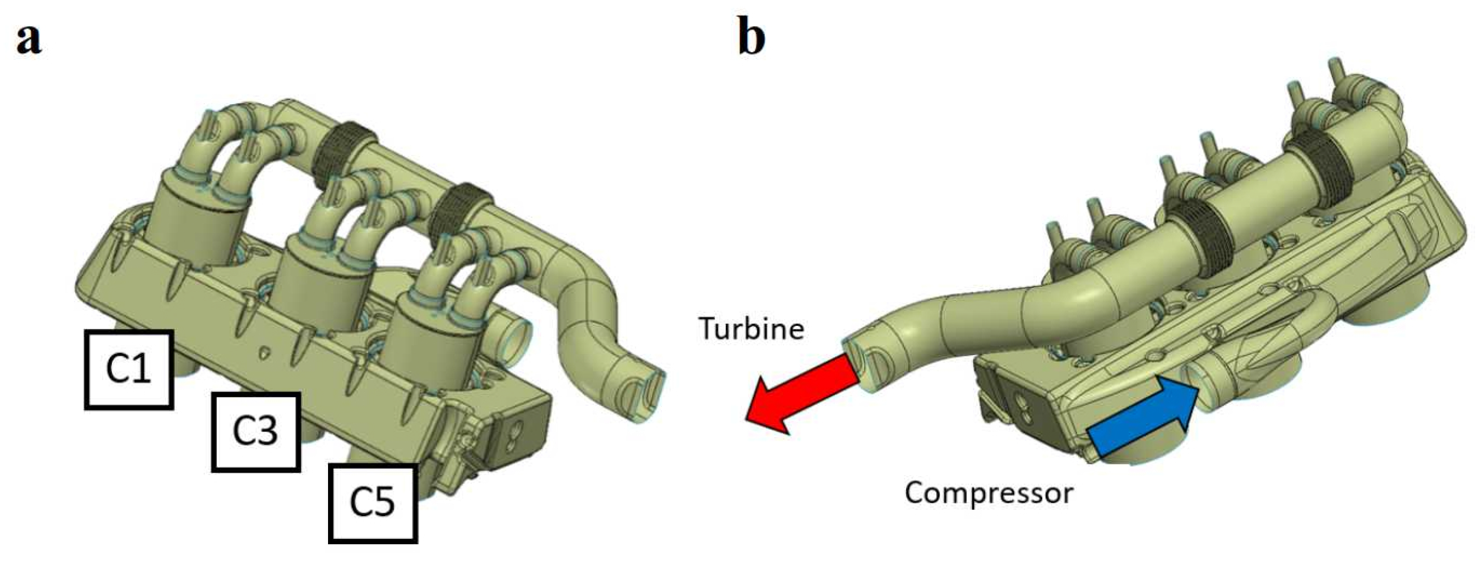
9], in this work the intake ports SOA is increased while keeping constant the ports cross-sectional area, in order to increase the swirl ratio by keeping nearly constant the fresh air mass delivered through ports. To the best of the authors’ knowledge, this is the first time that the scavenging process is studied by a 3D CFD model by considering the whole bank of a multi-cylinder engine. This choice, although very CPU time consuming, allows to evaluate the effects of the position of each cylinder in the bank with respect to the air intake pipe. Specifically, looking at the bank architecture shown in
Figure 1, it is questionable whether Cylinder 3 might be more favored than the others and whether the back pressure at the exhaust ducts plays a role on the scavenging performance. The simulations performed in this work will untangle these questions and will give important guidelines to improve the scavenging.
This work is organized as follows: at first, the test case is presented, then the model is described and its validation against experimental data is given, the results are discussed and, finally, the conclusions are summarized.
2. The GF56 Diesel Engine
The aim of the present work is to analyze and suggest improvements to the scavenging performance of an aircraft two-stroke uniflow engine, namely GF56, designed by
Costruzioni Motori Diesel (CMD) S.p.A. [
20]. GF56 is a diesel common-rail direct injection engine, with six cylinders in a boxer configuration and a total volume displacement of 5600 cc. The two banks of the engine are very much similar, thus only the right bank will be considered in the following. The right bank is depicted through the Computer-Aided Drafting (CAD) technique, shown in
Figure 1 along with cylinder-specific labels.
Table 1 gives the specifications of the engine.
The
x position of the piston head between Top Dead Center (TDC) and Bottom Dead Center (BDC) is a function of Crank Angle (CA), according to the following expression:
being the CA,
R the crank radius, and
the ratio
, with
l being the connecting rod length. The three pistons of the right bank move accordingly to Equation (
1) with a phase shifting of
, as shown in
Figure 2, where the grey-shaded zone represents the height and location of the intake ports. The three pistons open the intake ports as they cross the gray-shaded zone and the figure shows that only two pistons per time are simultaneously in such a zone for about
CA. For instance, in the range CA
of
Figure 2, Piston 3 and Piston 5 are in the gray-shaded zone simultaneously for only about
CA. Hence, the scavenging phase of a cylinder occurs for the most part while the other two cylinders intake ports are closed. As a consequence, it is assumed that the scavenging analysis can be performed by considering a single cylinder per time. This assumption leads to a noticeable reduction of the computational cost. Furthermore, the exhaust common manifold is not included in the computations in order to further reduce the computational cost.
The phase diagram reporting the opening and closure phase for exhaust valves and intake ports as a function of CA is given in
Figure 3, where
and
CA correspond to TDC and BDC, respectively. The exhaust and scavenging processes occur in the interval CA
, being the time period when the exhaust valves are opened.
4. Model Validation
In order to validate the computational model, a simulation has been performed by considering the whole cycle under motored conditions at 2000 rpm in order to compare the results with available measured data, in terms of in-chamber pressure. Air enters into the plenum at 310 K and 1.52 bar, whereas in the engine chamber the values of pressure and temperature at the start of the simulation, that is, 74 CAD, are equal to 2.94 bar and 340 K, respectively. At the outlet boundary, the pressure is equal to 1.38 bar and the temperature is equal to 380 K. Finally, the chamber walls temperature is equal to 340 K.
The in-chamber volume as a function of crank angle is given in
Figure 8, together with the in-chamber mass profile during the whole cycle.
Figure 9 shows the comparison between the numerical results and the measurements in terms of in-chamber pressure. In order to get a cyclic-converged solution, four engine work cycles have been simulated, thus achieving a good agreement with the measured pressure profile. It can be concluded that the numerical results during the scavenging process are in very good agreement with the experimental data, thus showing the accuracy of the model as the inlet ports and/or the exhaust valves are open.
5. Results and Discussion
At first, the scavenging process of the baseline case has been analyzed. Then, several simulations have been performed by ranging the inlet mass flow rate from 0.1 to 1.5 , to assess the engine performance for each case. Furthermore, the flow field of each cylinder of the right bank has been analyzed and results have been compared with each other. Finally, a geometrical modification of the intake ports is proposed to try to improve the charging efficiency of the engine. All the simulations are carried out by considering an engine rpm equal to 2000.
5.1. The Baseline Case
Contour plots of
Burned Gas mass fraction at different time instants are shown in
Figure 10 to highlight the scavenging features. A relevant amount of
Burned Gas remains in the piston cup and near the liner, and a small pocket of back-flow is found near the intake ports at the end of the scavenging process, that is, CA = 246
. In
Figure 11, contour plots of
Burned Gas mass fraction are shown for different time instants on the plane XZ. The figure shows the swirl flow induced by the intake ports and the presence of some residuals in the piston cup at the end of the scavenging process. Moreover, the last contour plots of the figure, that is, CA = 246
, shows that the back-flow of
Burned Gas regards only some of the intake ports.
The scavenging characteristics are quantified by evaluating three global parameters, namely the delivery ratio, the trapping efficiency and the charging efficiency [
5]. The delivery ratio is defined as the ratio between the mass of
Fresh Air delivered through the intake ports during the scavenging process,
, and the amount of
Fresh Air required to charge the cylinder by means of an ideal scavenging process, that is,
, where
is the displaced volume and
the reference air density. The trapping efficiency,
, corresponds to the actual amount of
Fresh Air trapped into the cylinder,
, at the end of the scavenging process (i.e., when the exhaust valves and the intake ports are fully closed) with respect to the total mass delivered through the intake ports,
. Finally, the charging efficiency,
, is the ratio between the trapped air mass and the ideal amount of
Fresh Air in the cylinder, and it corresponds to the delivery ratio multiplied by the trapping efficiency.
The use of air as a scavenging fluid is a common choice. Unfortunately, a certain amount of air flows away through the exhaust valves and this increases the work for pumping due to the amount of air which is lost. For this reason, the inlet mass flow rate is generally higher than the amount of air theoretically required to scavenge the cylinder. Indeed, the delivery ratio is commonly in a range between 1.0 and 1.4, corresponding to satisfactory scavenging performances.
The scavenging process under theoretical conditions can be described by two simplified models [
13]. On one side, the perfect displacement model considers that the burned gases are pushed out by the fresh air without any mixing between them. On the other hand, the perfect mixing assumes that the incoming fresh air mixes instantaneously and uniformly with the gas mixture already in the cylinder. As a matter of fact, the real scavenging process will be in between such models and will differ from both.
For the baseline case, the delivery ratio is equal to 1.36, the trapping efficiency is equal to 0.54 and, finally, the charging efficiency is 0.73. These efficiencies are close to those corresponding to a perfect mixing condition.
5.2. Influence of Inlet Mass Flow Rate
Several simulations have been performed by varying the inlet mass-flow rate, G, from 0.1 G
to 1.5 G
, with G
= 0.2249 kg/s.
Figure 12a shows the mass flow rate of
Fresh Air through the intake ports as a function of time for the different cases. The flow rate is assumed to be negative for fresh air entering into the cylinder, otherwise it is assumed to be positive. As expected, by increasing G, the flow rate of fresh air entering into the cylinder increases as well. At about CA =
the mass flow rate decreases for all cases and, for the lowest G, a back-flow occurs. A back-flow is also found for all cases at the end of the scavenging, that is, CA
. In
Figure 12b, the
Burned Gas (BG) mass fraction profiles are given based on the relationship between the BG mass fraction in the cylinder, along the
x-axis, and the BG mass fraction in the exhaust ducts, along the
y-axis. The figure shows the short-circuiting phenomenon for different inlet mass flow rates. Indeed, it can be observed that, with the lower mass flow rates, the
Fresh Air enters into the exhaust pipes faster, thus diverging from the perfect displacement condition. The lowest appearance of the short-circuiting phenomenon is observed with 0.8
. Nevertheless, the higher the intake mass flow rate, the lower the percentage of
Burned Gas in the cylinder at the end of the scavenging process.
In
Figure 12c,d, the trapping and the charging efficiency, respectively, are plotted as a function of the delivery ratio. Each square symbol corresponds to a given inlet mass flow rate. The figure shows that the delivery ratio increases with the inlet mass flow rate. As expected, the trapping efficiency decreases with increasing delivery ratio, whereas the charging efficiency increases with the delivery ratio. The perfect mixing profile is also shown in the figures, to demonstrate that, for small delivery ratios,
is higher than that of the perfect mixing, whereas for larger values it approaches the perfect mixing condition.
Figure 12e depicts the projection of the velocity field vectors on the XZ middle-height plane of the cylinder. The figure clearly shows the swirl motion that develops into the cylinder as a consequence of the inlet ports angle. As the inlet mass flow rate increases, higher velocities are obtained, corresponding to a higher swirl ratio in the cylinder. The values of the swirl ratio are given in
Table 3. The table shows that, for the baseline mass flow rate G
, the swirl ratio is about 2, which corresponds to a typical value for this type of engine.
5.3. Influence of Cylinder Number and Outlet Boundary Conditions
A computational analysis has also been performed for Cylinder 1 and Cylinder 5, and the scavenging performances of all the three cylinders are finally compared. The measured pressure profiles at the outlet sections differ for the three cylinders, as given in
Figure 13. However, the same initial burned gas pressure is set for all the cylinders, since the three values are very close to each other at CA = 74
. The remaining initial and boundary conditions are the same as for the baseline case, as well as the computational mesh.
The
Fresh Air flow rate through the intake ports is plotted in
Figure 14a for the three cylinders with G
= 0.2249 kg/s. Specifically, Cylinder 1 shows a back-flow through intake ports at about 135
CA. This is because the pressure at the exhaust section, at 135
CA, has a peak for Cylinder 1 with respect to the other cylinders, as shown in
Figure 13.
The mass of
Fresh Air trapped into the three cylinders has been computed along with the cylinder total mass, i.e., the sum of
Fresh Air mass and
Burned Gas mass, and the results are given in
Figure 14b as a function of time. At the start of the simulation, as the exhaust valves open, the amount of mass in the cylinder decreases, whereas the
Fresh Air is still zero, up to the point that the intake ports open and both the total and the
Fresh Air mass in the cylinders increase. Due to the back-flow through intake ports, the increase of fluid mass in the cylinder is slower for Cylinder 1 with respect to the other two cylinders. Nevertheless, at the end of the scavenging process, the three profiles are very similar to each other. Moreover, some differences are observed in the
Burned Gas mass fraction profiles of
Figure 14c. Indeed, Cylinder 1 shows a faster appearance of the short-circuiting phenomenon but, at the end of the scavenging process, the BG mass fraction in the exhaust pipes is noticeably higher with respect to the other two cylinders, due to the different profiles of
Fresh Air mass flow rate through the intake ports, as reported in
Figure 14a. Cylinder 3 and Cylinder 5 have a similar behavior. To further investigate these differences, the instantaneous values of trapping efficiency and delivery ratio are computed for the three cylinders for the case
. The results are given in
Figure 14d, thus showing that, at the start of the scavenging process, all the air delivered through the intake ports is trapped within the cylinder, then the trapping efficiency decreases during the scavenging. At the end of the process, the final delivery ratio is higher for Cylinder 5, meaning that a higher amount of air is flowed through the intake ports with respect to Cylinder 3 and, even more, to Cylinder 1. However, the trapping efficiency is higher for Cylinder 1 with respect to Cylinder 3 and, even more, to Cylinder 5, thus showing that the scavenging process is more efficient for Cylinder 1.
The trapping and charging efficiencies are given as a function of delivery ratio in
Figure 14e,f, respectively. The figures show that the efficiency of Cylinder 5 is lower than that of the other two cases. Besides, the percentage of
Fresh Air trapped with respect to the in-cylinder total mass, given in
Table 4 for the baseline inlet mass flow rate, is lower for Cylinder 5 and higher for Cylinder 3. Notwithstanding the different behavior of the dynamic of the scavenging process, however, this percentage is about 92% for all of the three cylinders.
In order to understand whether such differences are due to the specific position of the three cylinders and/or to the pressure at the outlet section, further simulations have been performed by using the same boundary conditions, as for the baseline case, for all the three cylinders. The results are given in
Figure 15a,b. Slight differences are now obtained for the three cylinders. Cylinder 3, which is in the mid-located, is the most favorable to reach higher efficiencies for all cases, whereas the Cylinder 5 location is the worst one with higher delivery ratios. Based on the
Burned Gas mass fraction profiles of
Figure 15c, the Cylinder 1 profile departs from the perfect displacement condition later but faster, thus obtaining similar results at the end of the scavenging process like the other cylinders.
It can be concluded that the exhaust pressure profile plays a major role in the scavenging outcome of the three cylinders, in agreement with the scientific literature [
10], whereas the cylinders position has a minor effect on the scavenging efficiencies.
Negligible differences are expected by comparing the results obtained with the left and right banks, since the bank geometries are very similar. In order to confirm this issue, the scavenging performances of Cylinder 3, belonging to the right bank, and of Cylinder 4, being the corresponding mid-way cylinder of the left bank, have been compared. The simulation of Cylinder 4 has been performed by using the same initial and boundary conditions of the baseline case, in order to investigate only the role of the different locations.
The results are given in
Figure 16 in terms of trapping and charging efficiencies versus delivery ratio. Negligible differences between Cylinder 3 and Cylinder 4 performances are obtained.
5.4. Influence of the Intake Ports Geometry
In order to increase the tangential velocity of
Fresh Air flow through the intake ports, a geometry modification of such ports is proposed. Specifically, as shown in
Figure 17, the intake ports angle is increased by 22
, while keeping constant the ports cross-sectional area in correspondence of the cylinder. This choice enables to increase the swirl ratio, in agreement with the scientific literature [
9], but keeping nearly constant the delivery ratio with respect to the previous geometry.
The contour plot of the
Burned Gas mass fraction is shown in
Figure 18 at different time instants. By comparing these results with those obtained with the initial configuration, given in
Figure 10, a partially unscanveged zone can be observed close to the cylinder axis, whereas burned gas is not found near the liner throughout the whole scavenging process. This is the result of the increase of the swirl motion, which helps to scavenge the regions near the cylinder walls at the expense of the central region of the chamber. On the contrary, in the previous geometry a certain amount of
Burned Gas remains near the cylinder liner. It is worth noting that the volume enclosed in the near-axis zone of a cylinder is much smaller than the volume enclosed in the near-liner region of the same cylinder.
Trapping and charging efficiencies as a function of the delivery ratio are given in
Figure 19b,c, respectively. The results show that the delivery ratio only slightly decreases with the new configuration with respect to the previous one. Both the trapping and the charging efficiencies improve with the new geometry and with delivery ratios higher than 1.1, which is the range of interest for such an engine, whereas the opposite occurs with lower values of the delivery ratio.
Figure 19c shows that with
and the new ports configuration, the profile of
Burned Gas mass fraction in the exhaust pipes versus
Burned Gas mass fraction in the cylinder is somewhat closer to the perfect displacement condition with respect to the previous geometry. This is due to the different velocity field obtained with the new intake ports geometry, as shown in
Figure 19d. With the new configuration, the in-cylinder tangential velocity noticeably increases, leading to a substantial increase of the swirl ratio, equal to about 3.94.
6. Conclusions
A detailed 3D CFD investigation of the scavenging process of a uniflow, two-stroke, multi-cylinder engine, named GF56, has been carried out. GF56 is a diesel common-rail direct injection engine for the general aviation market, with six cylinders in a boxer configuration and a total volume displacement of 5600 cc.
The right bank has been analyzed by considering the plenum, the intake manifold, all cylinders and the exhaust pipes. The results are analyzed in terms of trapping and charging efficiencies to show that the cylinders are characterized by similar scavenging performances, with Cylinder 5 slightly under-performing. The fresh air trapped for each cylinder during the scavenging process is quite similar, being about 92% of the in-cylinder mass. The scavenging process is strongly influenced by the pressure at the outlet section. Indeed, with the same exhaust pressure for all of the three cylinders, the differences are negligible and the scavenging profiles are almost on top of each other, with a somewhat lower efficiency, at high delivery ratios, for Cylinder 5, which is in the less favored position. These results show that the position of the cylinders in the bank plays a minor role and that the same pressure profile at the exhaust is able to provide a similar scavenging performance for all the cylinders.
Moreover, a comparison between left and right banks of the engine is provided with very similar performances for both banks as a consequence of their quasi-specularity.
Finally, the influence of the intake ports geometry has been analyzed. Specifically, a modification of such a geometry of the ports is proposed to increase the swirl ratio of the in-cylinder flow field by keeping the delivery ratio nearly constant. This new geometry configuration leads to a considerable increase of the swirl ratio and provides better scavenging performance with delivery ratios generally employed during engine running conditions.


 ,
, 


